relay RENAULT TWINGO RS 2009 2.G Heating And Air Conditioning - Heating Workshop Manual
[x] Cancel search | Manufacturer: RENAULT, Model Year: 2009, Model line: TWINGO RS, Model: RENAULT TWINGO RS 2009 2.GPages: 29
Page 9 of 29
61A-9
MR-413-X44-61A000$500_eng.mif
V1
HEATING
Fault finding - Function61A
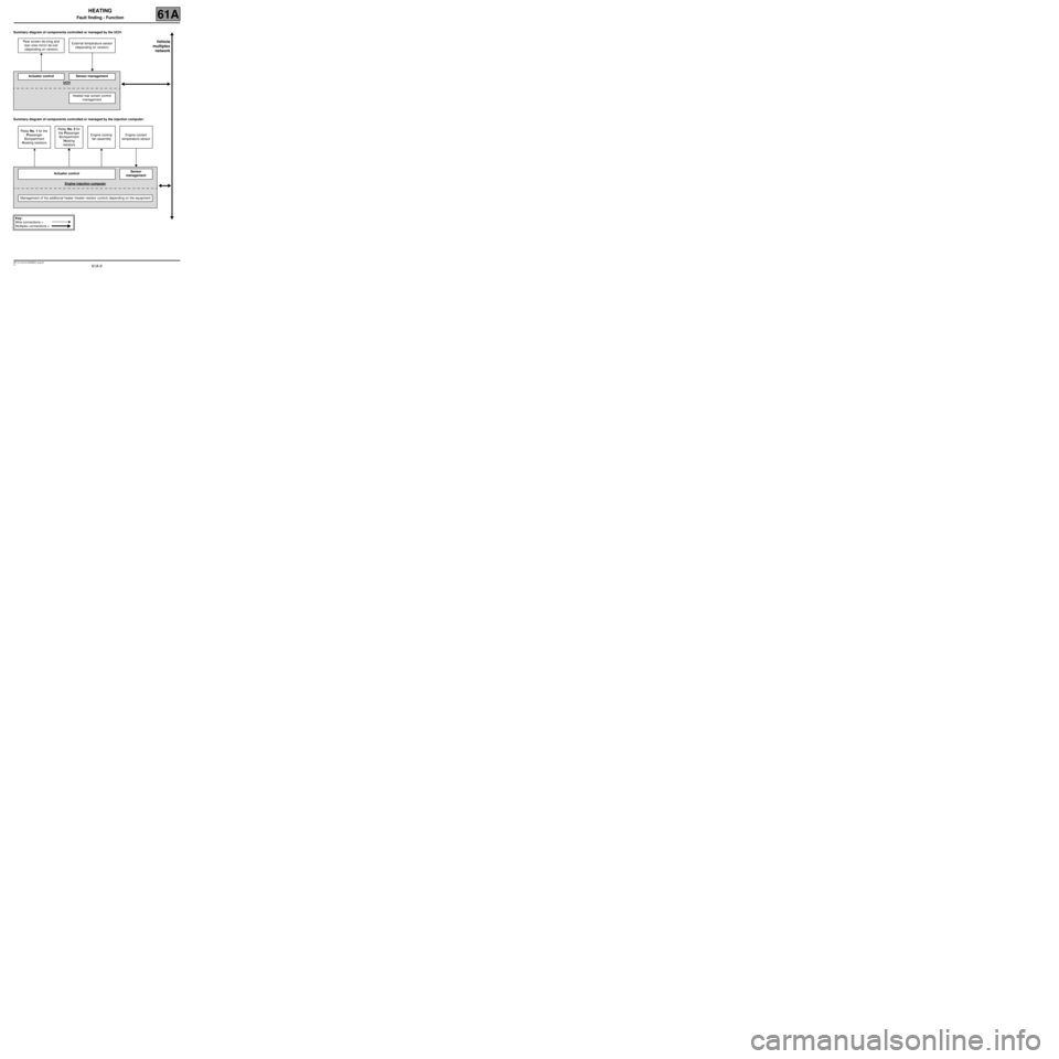
Summary diagram of components controlled or managed by the UCH:
Summary diagram of components controlled or managed by the injection computer:Rear screen de-icing and
rear-view mirror de-icer
(depending on version)External temperature sensor
(depending on version)
Actuator controlSensor management
UCH
Heated rear screen control
management
Relay No. 1 for the
Passenger
Compartment
Heating resistorsRelay No. 2 for
the Passenger
Compartment
Heating
resistorsEngine cooling
fan assemblyEngine coolant
temperature sensor
Actuator controlSensor
management
Engine injection computer
Management of the additional heater (heater resistor control) depending on the equipment
Key:
Wire connections =
Multiplex connections =
Vehicle
multiplex
network
Page 17 of 29
61A-17
MR-413-X44-61A000$625_eng.mif
V1
HEATING
Fault finding - Conformity check61A
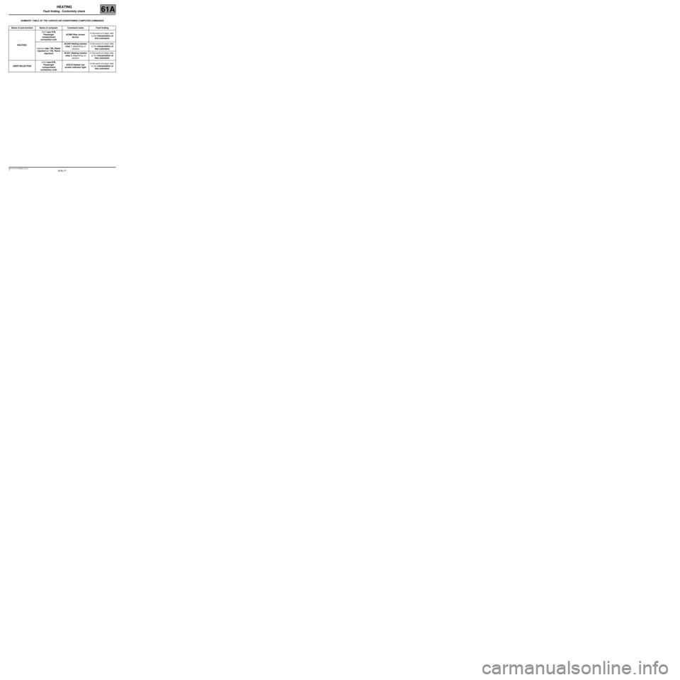
SUMMARY TABLE OF THE VARIOUS AIR CONDITIONING COMPUTER COMMANDS
Name of sub-function Name of computer Command name Fault finding
HEATINGUCH (see 87B,
Passenger
compartment
connection unit)AC060 Rear screen
de-icerIn the event of a fault, refer
to the interpretation of
this command.
Injection (see 13B, Diesel
injection or 17B, Petrol
injection)AC250 Heating resistor
relay 1 (depending on
version)In the event of a fault, refer
to the interpretation of
this command.
AC251 Heating resistor
relay 2 (depending on
version)In the event of a fault, refer
to the interpretation of
this command.
USER SELECTIONUCH (see 87B,
Passenger
compartment
connection unit)AC019 Heated rear
screen indicator lightIn the event of a fault, refer
to the interpretation of
this command.
Page 21 of 29
61A-21
MR-413-X44-61A000$875_eng.mif
V1
HEATING
Fault finding - Fault finding charts61A
ALP 6
CONTINUED 2
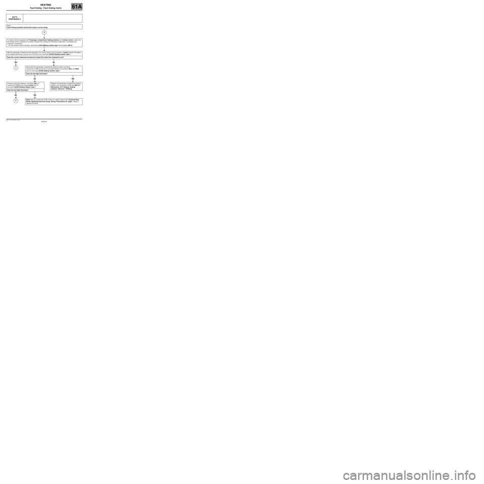
Note:
Fault finding procedure performed using a current clamp.
For diesel vehicles equipped with Passenger compartment heating resistors and climate control, check that
the climate control computer is correctly configured by reading the following configuration (reconfigure the
computer if necessary):
–For the climate control computer, parameter LC044 Heating resistor type should display 900 W.
With the passenger compartment fan activated, fit a current clamp to the connection of earth between the battery
and chassis earth point, and use the CLIP tool to run command AC250 Heating resistor relay 1.
Does the current measured increase by at least 20 A when the command is run?
YES NO
Connect a test light between connection 38LL of
component 1113 and the chassis earth and run
command AC250 Heating resistor relay 1.
Does the test light illuminate?
NO YES
Disconnect the passenger compartment heating resistor connector
(component 1113) and connect a test light between connections 38LL and MAK
and run command AC250 Heating resistor relay 1.
Does the test light illuminate?
NO YES
Replace the passenger compartment heating
resistor unit (component 1113) (see MR 411,
Mechanical, 61A, Heating, Heating
resistors: Removal - Refitting).
Earth fault on component 1113. If there is a repair method (see Technical Note
6015A, Repairing electrical wiring, W iring: Precautions for repair), repair or
replace the wiring.
B
C
D
Page 22 of 29
61A-22
MR-413-X44-61A000$875_eng.mif
V1
HEATING
Fault finding - Fault finding charts61A
ALP 6
CONTINUED 3
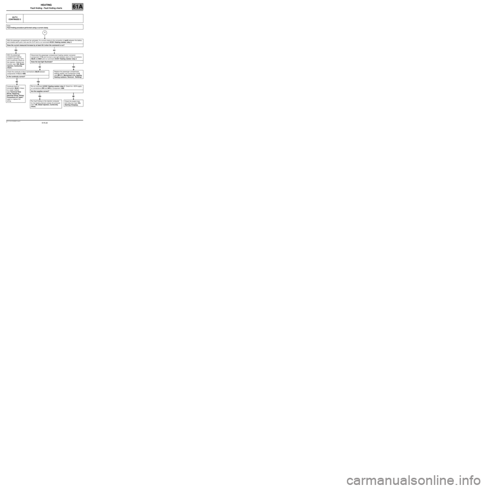
Note:
Fault finding procedure performed using a current clamp.
With the passenger compartment fan activated, fit a current clamp to the connection of earth between the battery
and chassis earth point, and use the CLIP tool to run command AC251 Heating resistor relay 2.
Does the current measured increase by at least 40 A when the command is run?
YES NO
With the passenger
compartment heating
resistors operating, carry
out a conformity check on
the injection, heating sub-
function (see 13B, Diesel
injection, Conformity
check).
Disconnect the passenger compartment heating resistor connector
(component 1113) and connect a test light between each of the connections
38LM and MAK and run command AC251 Heating resistor relay 2.
Does the test light illuminate?
NO YES
Replace the passenger compartment
heating resistor unit (component 1113)
(see MR 411, Mechanical, 61A, Heating,
Heating resistors: Removal - Refitting).Check the continuity of the 2 connections 38LM between
components 1113 and 1068.
Is the continuity correct?
NO YES
Continuity fault on
connection 38LM. If there
is a repair method
(see Technical Note
6015A, Repairing
electrical wiring, Wiring:
Precautions for repair),
repair or replace the
wiring.Re-run command AC251 Heating resistor relay 2. Check for + 12 V supply
on connections 3FB and BP9 of component 1068.
Are the supplies correct?
YES NO
Check the engine fuse
and relay box (see 16A,
Starting Charging).Run fault finding on the injection computer
for the heating element resistor 2 command
(see 13B, Diesel injection, Conformity
check).
C
Page 23 of 29
61A-23
MR-413-X44-61A000$875_eng.mif
V1
HEATING
Fault finding - Fault finding charts61A
ALP 6
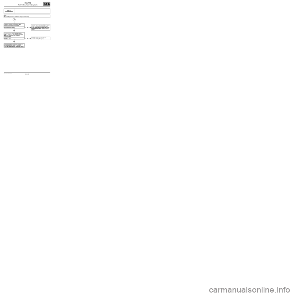
CONTINUED 4
Note:
Fault finding procedure performed using a current clamp.
Check the continuity on connection 38LL
between components 1113 and 1067.
Is the continuity correct?
YES
Re-run command AC250 Heating resistor
relay 1. Check for + 12 V between the chassis
earth and connections 3FB and BP9 of
component 1067.
Is there + 12 V?
YES
Run fault finding on the injection computer for
the heating element resistor 1 command
(see 13B, Diesel injection, Conformity check).
NOContinuity fault on connection 38LL. If there is
a repair procedure (see Technical Note
6015A, Repairing electrical wiring, Wiring:
Precautions for repair), repair the wiring or
replace it
.
NOCheck the engine fuse and relay box
(see 16A, Starting Charging).
D
Page 24 of 29
61A-24
MR-413-X44-61A000$875_eng.mif
V1
HEATING
Fault finding - Fault finding charts61A
ALP 6
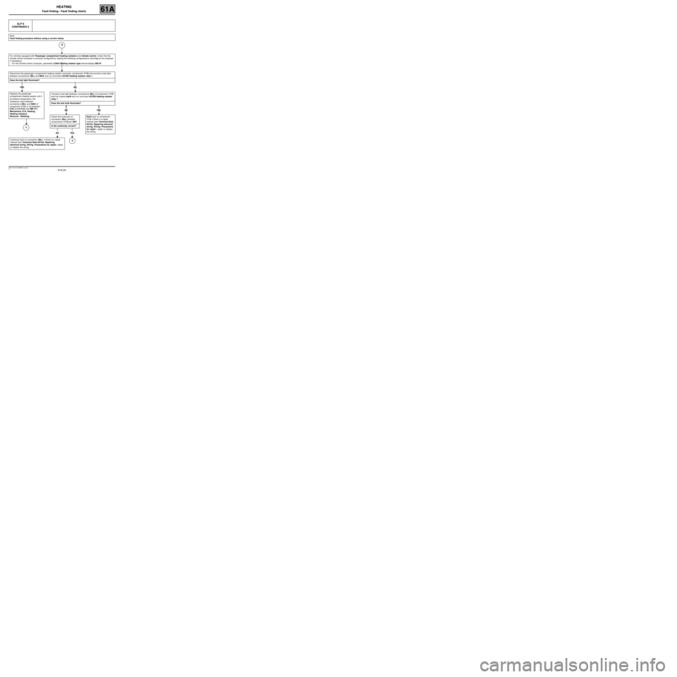
CONTINUED 5
Note:
Fault finding procedure without using a current clamp.
For vehicles equipped with Passenger compartment heating resistors and climate control, check that the
climate control computer is correctly configured by reading the following configurations (reconfigure the computer
if necessary):
–For the climate control computer, parameter LC044 Heating resistor type should display 900 W.
Disconnect the passenger compartment heating resistor connector (component 1113) and connect a test light
between connections 38LL and MAK and run command AC250 Heating resistor relay 1.
Does the test light illuminate?
YES NO
Replace the passenger
compartment heating resistor unit if,
at ambient temperature, the
resistance value between
connections 38LL and MAK of
component 1113, is not between:
0.55 and 0.75 ΩΩ Ω Ω
(see MR 411,
Mechanical, 61A, Heating,
Heating resistors:
Removal - Refitting).
Connect a test light between connections 38LL of component 1113
and the chassis earth and run command AC250 Heating resistor
relay 1.
Does the test bulb illuminate?
NO YES
Earth fault on component
1113. If there is a repair
method (see Technical Note
6015A, Repairing electrical
wiring, Wiring: Precautions
for repair), repair or replace
the wiring.
B
Check the continuity on
connection 38LL between
components 1113 and 1067.
Is the continuity correct?
NO YES
Continuity fault on connection 38LL. If there is a repair
method (see Technical Note 6015A, Repairing
electrical wiring, Wiring: Precautions for repair), repair
or replace the wiring.D
C
Page 25 of 29
61A-25
MR-413-X44-61A000$875_eng.mif
V1
HEATING
Fault finding - Fault finding charts61A
ALP 6
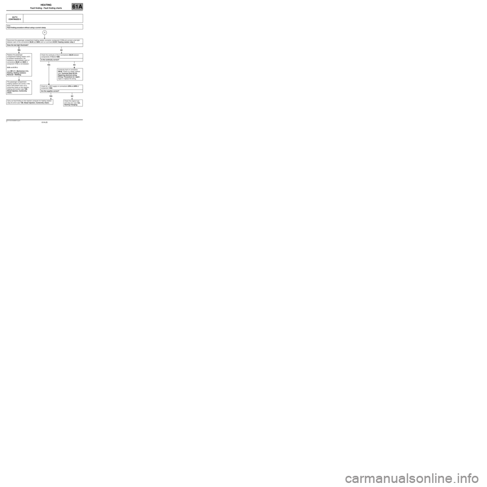
CONTINUED 6
Note:
Fault finding procedure without using a current clamp.
Disconnect the passenger compartment heating resistor connector (component 1113) and connect a test light
between each of the connections 38LM and MAK and run command AC251 Heating resistor relay 2.
Does the test light illuminate?
YES NO
Replace the passenger
compartment heating resistor unit if,
at ambient temperature, the
resistance value between each of
connections 38LM and MAK of
component 1113, is not between:
0.55 and 0.75 Ω
(see MR 411, Mechanical, 61A,
Heating, Heating resistors:
Removal - Refitting).
The passenger compartment
heating resistors are correct, if the
fault is still present carry out a
conformity check on the injection,
heating sub-function (see 13B,
Diesel injection, Conformity
check).
Check the continuity of the 2 connections 38LM between
components 1113 and 1068.
Is the continuity correct?
YES NO
Continuity fault on connection
38LM. If there is a repair method
(see Technical Note 6015A,
Repairing electrical wiring,
Wiring: Precautions for repair),
repair or replace the wiring.
Check for + 12 V supply on connections 3FB and BP9 of
component 1068.
Are the supplies correct?
YES NO
Check the engine fuse
and relay box (see 16A,
Starting Charging).Carry out fault finding on the injection computer for heating resistor
relay 2 control (see 13B, Diesel injection, Conformity check).
C
Page 26 of 29
61A-26
MR-413-X44-61A000$875_eng.mif
V1
HEATING
Fault finding - Fault finding charts61A
ALP 6
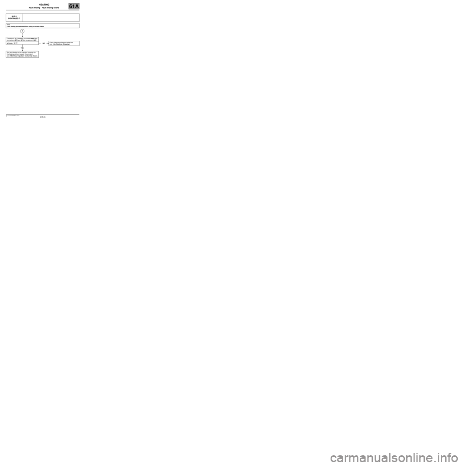
CONTINUED 7
Note:
Fault finding procedure without using a current clamp.
Check for + 12 V between the chassis earth and
connections 3FB and BP9 of component 1067.
Is there + 12 V?
YES
Run fault finding on the injection computer for
the heating element resistor 1 command
(see 13B, Diesel injection, Conformity check).
NOCheck the engine fuse and relay box
(see 16A, Starting - Charging)
D
Page 29 of 29
61A-29
MR-413-X44-61A000$875_eng.mif
V1
HEATING
Fault finding - Fault finding charts61A
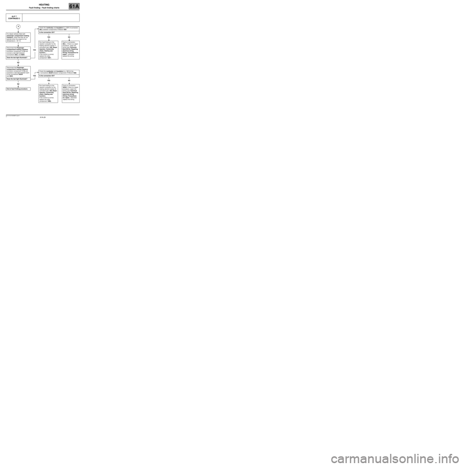
ALP 7
CONTINUED 2
For diesel vehicles fitted with
passenger compartment heating
resistors, check that they do not
operate when the engine is hot
(temperature > 50 ˚C).
Disconnect the Passenger
compartment heating resistors
connector (component 1113) and
connect a test light between
connections 38LL and MAK.
Does the test light illuminate?
NO
Disconnect the Passenger
compartment heating resistors
connector (component 1113) and
connector a test light between each
of the connections 38LM
and MAK.
Does the test light illuminate?
NO
End of fault finding procedure.
Check the continuity and insulation to + 12 V of connection
38LL between components 1113 and 1067.
Is the connection OK?
YES NO
YESRun fault finding on the
injection computer for the
heating element resistor 1
command (see 13B, Diesel
injection, Conformity
check, Heating sub-
function ).
If the control is correct,
replace the relay
(component 1067).Fault on connection
38LL, if there is a repair
procedure, repair the
wiring (see Technical
Note 6015A, Repairing
electrical wiring,
Wiring: Precautions for
repair), otherwise
replace the wiring.
Check the continuity and insulation to + 12 V of the
2 connections 38LM between components 1113 and 1068.
YES Is the connection OK?
YES NO
Run fault finding on the
injection computer for the
heating element resistor 2
command (see 13B, Diesel
injection, Conformity
check, Heating sub-
function).
If the control is correct,
replace the relay
(component 1068).Fault on connection
38LM, if there is a repair
procedure, repair the
wiring (see Technical
Note 6015A, Repairing
electrical wiring,
Wiring: Precautions
for repair), otherwise
replace the wiring.
B