display RENAULT ZOE 2017 1.G Owner's Manual
[x] Cancel search | Manufacturer: RENAULT, Model Year: 2017, Model line: ZOE, Model: RENAULT ZOE 2017 1.GPages: 220, PDF Size: 4.07 MB
Page 82 of 220
1.76
External temperature
indicator
As ice formation is related
to climatic exposure, local
air humidity and temperature, the
external temperature alone is not
sufficient to detect ice.
External temperature
indicator
Special note:
When the outside temperature is – 3°C
to + 3°C, the °C characters flash (sig-
nalling a risk of ice on the road).B
End
Clock
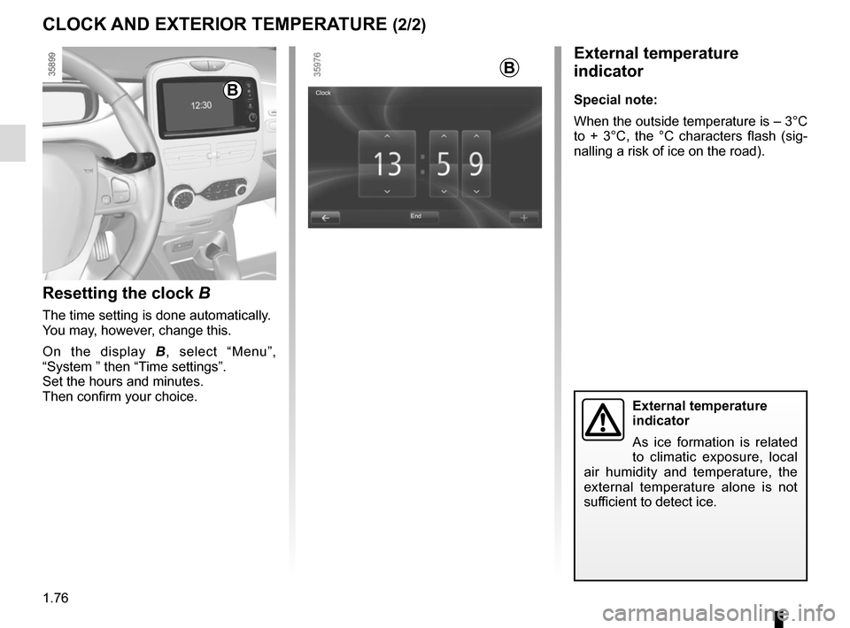
Resetting the clock B
The time setting is done automatically.
You may, however, change this.
On the display
B, select “Menu”,
“System ” then “Time settings”.
Set the hours and minutes.
Then confirm your choice.
B
CLOCK AND EXTERIOR TEMPERATURE (2/2)
Page 99 of 220
2.5
Only engage D or R when the vehi-
cle is stopped, with your foot on the
brake and the accelerator pedal re-
leased.
Driving
While driving, press the accelerator
pedal to achieve the desired speed.
The reversing lights will come on as
soon as reverse gear is selected (with
the ignition on).
GEAR CONTROL (1/2)
2
1
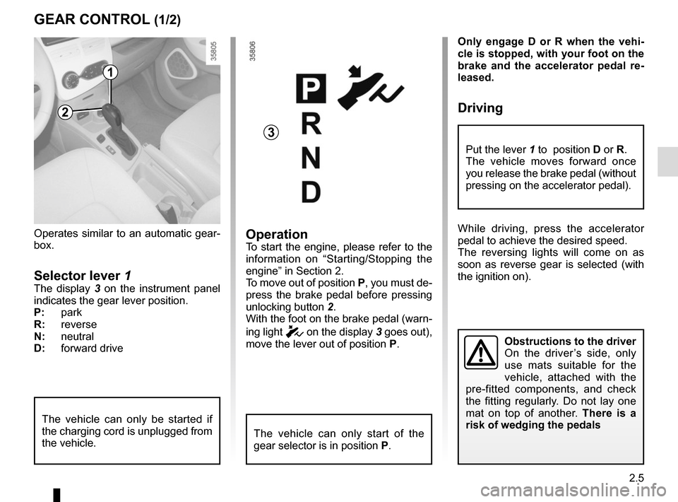
Operates similar to an automatic gear-
box.
Selector lever 1The display 3 on the instrument panel
indicates the gear lever position.
P: park
R: reverse
N: neutral
D: forward drive
OperationTo start the engine, please refer to the
information on “Starting/Stopping the
engine” in Section 2.
To move out of position P, you must de-
press the brake pedal before pressing
unlocking button 2.
With the foot on the brake pedal (warn-
ing light
c on the display 3 goes out),
move the lever out of position P.
The vehicle can only start of the
gear selector is in position P.
The vehicle can only be started if
the charging cord is unplugged from
the vehicle.
Obstructions to the driver
On the driver’s side, only
use mats suitable for the
vehicle, attached with the
pre-fitted components, and check
the fitting regularly. Do not lay one
mat on top of another. There is a
risk of wedging the pedals
Put the lever 1 to position D or R.
The vehicle moves forward once
you release the brake pedal (without
pressing on the accelerator pedal).
3
Page 101 of 220
2.7
DRIVING ADVICE, ECO-DRIVING (1/3)
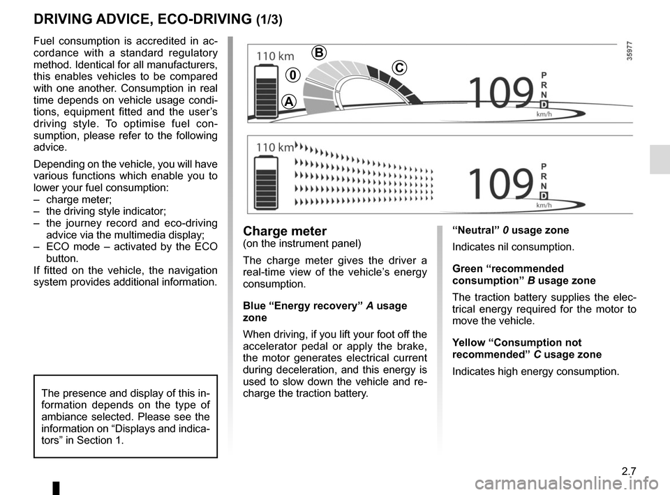
“Neutral” 0 usage zone
Indicates nil consumption.
Green “recommended
consumption” B usage zone
The traction battery supplies the elec-
trical energy required for the motor to
move the vehicle.
Yellow “Consumption not
recommended” C usage zone
Indicates high energy consumption.Charge meter(on the instrument panel)
The charge meter gives the driver a
real-time view of the vehicle’s energy
consumption.
Blue “Energy recovery” A usage
zone
When driving, if you lift your foot off the
accelerator pedal or apply the brake,
the motor generates electrical current
during deceleration, and this energy is
used to slow down the vehicle and re-
charge the traction battery.
Fuel consumption is accredited in ac-
cordance with a standard regulatory
method. Identical for all manufacturers,
this enables vehicles to be compared
with one another. Consumption in real
time depends on vehicle usage condi-
tions, equipment fitted and the user’s
driving style. To optimise fuel con-
sumption, please refer to the following
advice.
Depending on the vehicle, you will have
various functions which enable you to
lower your fuel consumption:
– charge meter;
– the driving style indicator;
– the journey record and eco-driving
advice via the multimedia display;
– ECO mode – activated by the ECO button.
If fitted on the vehicle, the navigation
system provides additional information.
The presence and display of this in-
formation depends on the type of
ambiance selected. Please see the
information on “Displays and indica-
tors” in Section 1.
A
B
C0
Page 102 of 220
2.8
Journey log (Driving ECO²
Score)
When the engine is switched off,
“Journey record” shows on the multi-
media display 2, for equipped vehicles,
letting you see information about your
last journey.
This indicates:
– average energy consumption;
– number of miles/kilometres travelled.
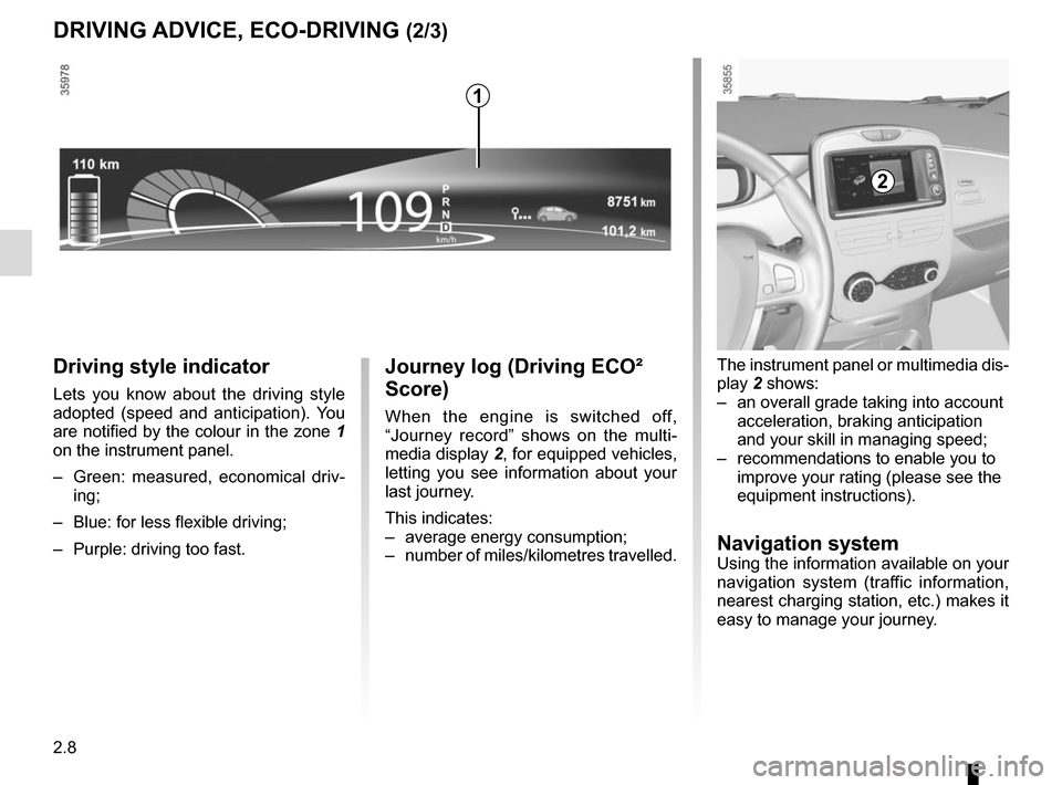
Driving style indicator
Lets you know about the driving style
adopted (speed and anticipation). You
are notified by the colour in the zone 1
on the instrument panel.
– Green: measured, economical driv- ing;
– Blue: for less flexible driving;
– Purple: driving too fast.
DRIVING ADVICE, ECO-DRIVING (2/3)
The instrument panel or multimedia dis-
play 2 shows:
– an overall grade taking into account acceleration, braking anticipation
and your skill in managing speed;
– recommendations to enable you to improve your rating (please see the
equipment instructions).
Navigation systemUsing the information available on your
navigation system (traffic information,
nearest charging station, etc.) makes it
easy to manage your journey.
2
1
Page 103 of 220
2.9
ECO mode
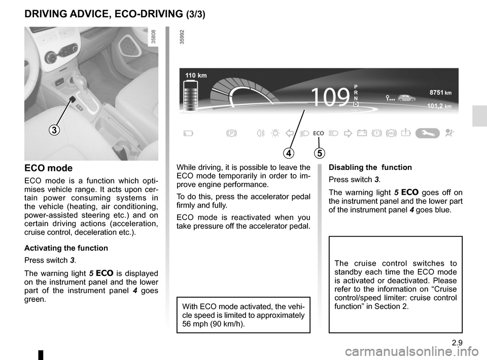
ECO mode is a function which opti-
mises vehicle range. It acts upon cer-
tain power consuming systems in
the vehicle (heating, air conditioning,
power-assisted steering etc.) and on
certain driving actions (acceleration,
cruise control, deceleration etc.).
Activating the function
Press switch 3.
The warning light 5
is displayed
on the instrument panel and the lower
part of the instrument panel 4 goes
green. Disabling the function
Press switch 3.
The warning light
5
goes off on
the instrument panel and the lower part
of the instrument panel 4 goes blue.
The cruise control switches to
standby each time the ECO mode
is activated or deactivated. Please
refer to the information on “Cruise
control/speed limiter: cruise control
function” in Section 2.
DRIVING ADVICE, ECO-DRIVING (3/3)
3
54
While driving, it is possible to leave the
ECO mode temporarily in order to im-
prove engine performance.
To do this, press the accelerator pedal
firmly and fully.
ECO mode is reactivated when you
take pressure off the accelerator pedal.
With ECO mode activated, the vehi-
cle speed is limited to approximately
56 mph (90 km/h).
Page 108 of 220
2.14
TYRE PRESSURE LOSS WARNING (2/3)
2
3
4
Note:
The standard tyre pressure cannot be
less than that recommended and indi-
cated on the door frame.
Display
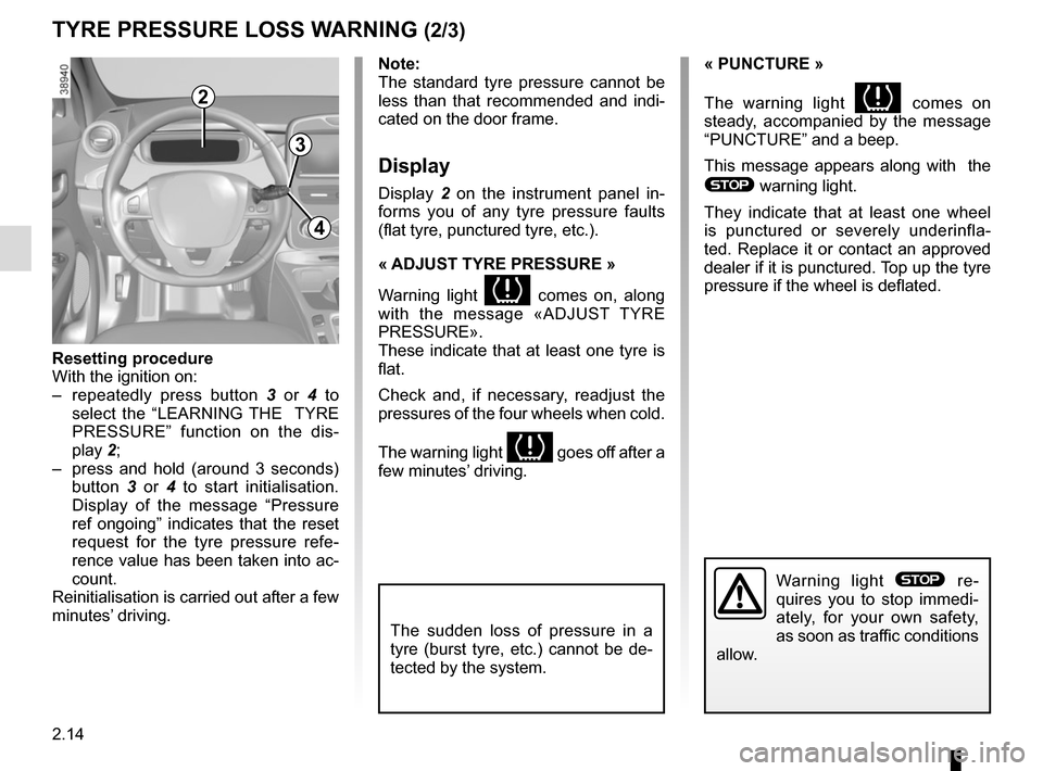
Display 2 on the instrument panel in-
forms you of any tyre pressure faults
(flat tyre, punctured tyre, etc.).
« ADJUST TYRE PRESSURE »
Warning light
comes on, along
with the message «ADJUST TYRE
PRESSURE».
These indicate that at least one tyre is
flat.
Check and, if necessary, readjust the
pressures of the four wheels when cold.
The warning light
goes off after a
few minutes’ driving.
« PUNCTURE »
The warning light
comes on
steady, accompanied by the message
“PUNCTURE” and a beep.
This message appears along with the
® warning light.
They indicate that at least one wheel
is punctured or severely underinfla-
ted. Replace it or contact an approved
dealer if it is punctured. Top up the tyre
pressure if the wheel is deflated.
Warning light ® re-
quires you to stop immedi-
ately, for your own safety,
as soon as traffic conditions
allow.
Resetting procedure
With the ignition on:
– repeatedly press button 3 or 4 to
select the “LEARNING THE TYRE
PRESSURE” function on the dis-
play 2;
– press and hold (around 3 seconds) button 3 or 4 to start initialisation.
Display of the message “Pressure
ref ongoing” indicates that the reset
request for the tyre pressure refe-
rence value has been taken into ac-
count.
Reinitialisation is carried out after a few
minutes’ driving.
The sudden loss of pressure in a
tyre (burst tyre, etc.) cannot be de-
tected by the system.
Page 120 of 220
2.26
CRUISE CONTROL (3/4)
The cruise control function
is in no way linked to the
braking system.
Adjusting the cruising speed
The cruising speed may be changed by
pressing the following repeatedly:
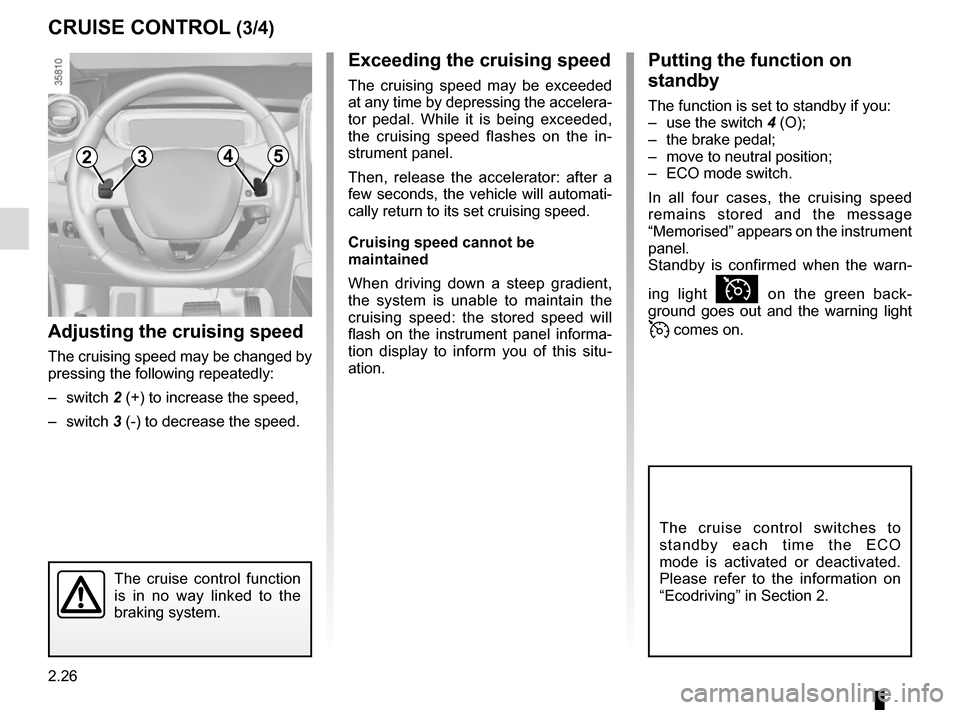
– switch 2 (+) to increase the speed,
– switch 3 (-) to decrease the speed.
Exceeding the cruising speed
The cruising speed may be exceeded
at any time by depressing the accelera-
tor pedal. While it is being exceeded,
the cruising speed flashes on the in-
strument panel.
Then, release the accelerator: after a
few seconds, the vehicle will automati-
cally return to its set cruising speed.
Cruising speed cannot be
maintained
When driving down a steep gradient,
the system is unable to maintain the
cruising speed: the stored speed will
flash on the instrument panel informa-
tion display to inform you of this situ-
ation.
2354
Putting the function on
standby
The function is set to standby if you:
– use the switch 4 (O);
– the brake pedal;
– move to neutral position;
– ECO mode switch.
In all four cases, the cruising speed
remains stored and the message
“Memorised” appears on the instrument
panel.
Standby is confirmed when the warn-
ing light
Ï on the green back-
ground goes out and the warning light
comes on.
The cruise control switches to
standby each time the ECO
mode is activated or deactivated.
Please refer to the information on
“Ecodriving” in Section 2.
Page 122 of 220
2.28
PARKING DISTANCE CONTROL (1/2)
Operating principle
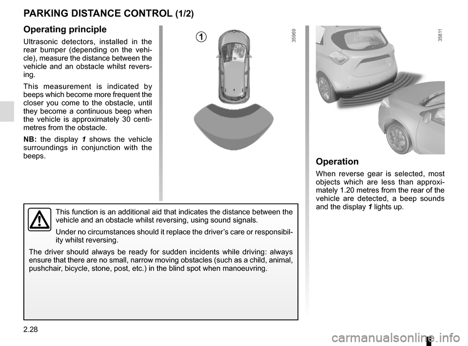
Ultrasonic detectors, installed in the
rear bumper (depending on the vehi-
cle), measure the distance between the
vehicle and an obstacle whilst revers-
ing.
This measurement is indicated by
beeps which become more frequent the
closer you come to the obstacle, until
they become a continuous beep when
the vehicle is approximately 30 centi-
metres from the obstacle.
NB: the display 1 shows the vehicle
surroundings in conjunction with the
beeps.
This function is an additional aid that indicates the distance between t\
he
vehicle and an obstacle whilst reversing, using sound signals.
Under no circumstances should it replace the driver’s care or responsibil-
ity whilst reversing.
The driver should always be ready for sudden incidents while driving: al\
ways
ensure that there are no small, narrow moving obstacles (such as a chil\
d, animal,
pushchair, bicycle, stone, post, etc.) in the blind spot when manoeuvring.
Operation
When reverse gear is selected, most
objects which are less than approxi-
mately 1.20 metres from the rear of the
vehicle are detected, a beep sounds
and the display 1 lights up.
1
Page 123 of 220
2.29
PARKING DISTANCE CONTROL (2/2)
In the event of an impact to
the underside of the vehicle
(e.g.: striking a post, raised
kerb or other street furni-
ture), this may result in damage to
the vehicle (e.g.: twisted axle), the
electrical circuit or the traction bat-
tery.
To avoid any risk of accident, have
your vehicle checked by an ap-
proved dealer.
Operating faults
Depending on the vehicle, when the
system detects an operating fault, the
message “check parking distance con-
trol” appears on the instrument panel,
accompanied by the warning light
© and a beep lasting approxi-
mately 5 seconds. Please contact an
authorised dealer.
Special featuresMake sure that the ultrasonic sensors
are not obscured (by dirt, mud, snow
etc.).
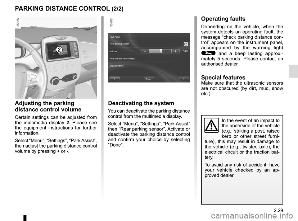
Adjusting the parking
distance control volume
Certain settings can be adjusted from
the multimedia display 2. Please see
the equipment instructions for further
information.
Select “Menu”, “Settings”, “Park Assist”,
then adjust the parking distance control
volume by pressing + or -.
2
Deactivating the system
You can deactivate the parking distance
control from the multimedia display.
Select “Menu”, “Settings”, “Park Assist”
then “Rear parking sensor”. Activate or
deactivate the parking distance control
and confirm your choice by selecting
“Done”.
Done
Park Assist
Rear parking sensor
Volume
Image settings Rear camera view settings
Page 124 of 220
2.30
REVERSING CAMERA (1/2)
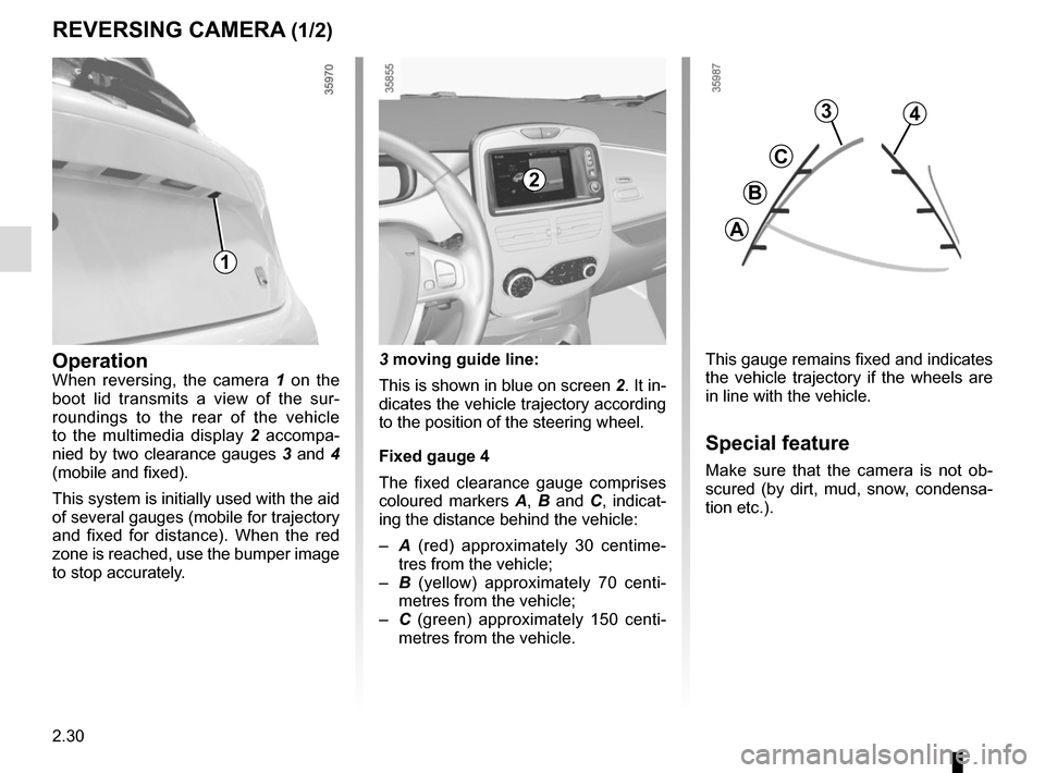
This gauge remains fixed and indicates
the vehicle trajectory if the wheels are
in line with the vehicle.
Special feature
Make sure that the camera is not ob-
scured (by dirt, mud, snow, condensa-
tion etc.).
OperationWhen reversing, the camera 1 on the
boot lid transmits a view of the sur-
roundings to the rear of the vehicle
to the multimedia display 2 accompa-
nied by two clearance gauges 3 and 4
(mobile and fixed).
This system is initially used with the aid
of several gauges (mobile for trajectory
and fixed for distance). When the red
zone is reached, use the bumper image
to stop accurately. 3 moving guide line:
This is shown in blue on screen
2. It in-
dicates the vehicle trajectory according
to the position of the steering wheel.
Fixed gauge 4
The fixed clearance gauge comprises
coloured markers A, B and C , indicat-
ing the distance behind the vehicle:
– A (red) approximately 30 centime-
tres from the vehicle;
– B (yellow) approximately 70 centi-
metres from the vehicle;
– C (green) approximately 150 centi-
metres from the vehicle.
3
C
B
A
4
2
1