lock SATURN OUTLOOK 2010 Service Manual
[x] Cancel search | Manufacturer: SATURN, Model Year: 2010, Model line: OUTLOOK, Model: SATURN OUTLOOK 2010Pages: 444, PDF Size: 4.43 MB
Page 113 of 444

Seats and Restraints 3-59
In Canada, the law requires that
forward-facing child restraints have
a top tether, and that the tether be
attached.
If the child restraint does not have
the LATCH system, you will be
using the safety belt to secure the
child restraint in this position. Be
sure to follow the instructions that
came with the child restraint. Secure
the child in the child restraint when
and as the instructions say.
If more than one child restraint
needs to be installed in the rear
seat, be sure to readWhere to Put
the Restraint on page 3‑50.
1. Put the child restraint on the seat.
2. Pick up the latch plate, and run the lap and shoulder portions of
the vehicle's safety belt through
or around the restraint. The child
restraint instructions will show
you how.
3. Push the latch plate into the
buckle until it clicks.
Position the release button on
the buckle so that the safety belt
could be quickly unbuckled if
necessary.4. Pull the rest of the shoulder beltall the way out of the retractor to
set the lock.
ProCarManuals.com
Page 116 of 444
3-62 Seats and Restraints
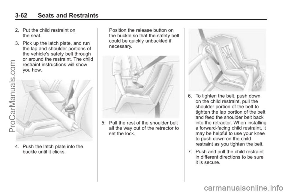
2. Put the child restraint onthe seat.
3. Pick up the latch plate, and run the lap and shoulder portions of
the vehicle's safety belt through
or around the restraint. The child
restraint instructions will show
you how.
4. Push the latch plate into thebuckle until it clicks. Position the release button on
the buckle so that the safety belt
could be quickly unbuckled if
necessary.
5. Pull the rest of the shoulder belt
all the way out of the retractor to
set the lock.
6. To tighten the belt, push downon the child restraint, pull the
shoulder portion of the belt to
tighten the lap portion of the belt
and feed the shoulder belt back
into the retractor. When installing
a forward-facing child restraint, it
may be helpful to use your knee
to push down on the child
restraint as you tighten the belt.
7. Push and pull the child restraint in different directions to be sure
it is secure.
ProCarManuals.com
Page 119 of 444

Storage 4-1
Storage
Storage Compartments
Instrument Panel Storage . . . . 4-1
Glove Box . . . . . . . . . . . . . . . . . . . . 4-1
Cupholders . . . . . . . . . . . . . . . . . . . 4-1
Armrest Storage . . . . . . . . . . . . . . 4-1
Center Console Storage . . . . . . 4-1
Floor Console Storage . . . . . . . . 4-2
Additional Storage Features
Cargo Cover . . . . . . . . . . . . . . . . . . 4-3
Cargo Tie Downs . . . . . . . . . . . . . 4-3
Cargo ManagementSystem . . . . . . . . . . . . . . . . . . . . . . 4-3
Convenience Net . . . . . . . . . . . . . 4-3
Roof Rack System
Roof Rack System . . . . . . . . . . . . 4-4
Storage
Compartments
Instrument Panel Storage
This vehicle has an instrument
panel storage area located above
the radio. To open the cover, press
the button.
Glove Box
Lift the glove box handle up to open
it. Use the key to lock and unlock
the glove box.
Cupholders
There are two cupholders, with
removable liners, located in front of
the center console. There may be
cupholders located in the second
row seat armrest. To access, pull
the armrest down. There are
additional cupholders located on
each side of the third row seat and
in each door. There may be cupholders located at
the rear of the center console. To
access, pull the handle down.
Armrest Storage
Vehicles with a rear seat armrest,
have two cupholders. Pull the
armrest down from the rear
seatback to access the cupholders.
Center Console Storage
Pull up on the lever, located on the
front of the center console armrest,
to slide it forward and backward.
ProCarManuals.com
Page 123 of 444

Instruments and Controls 5-1
Instruments and
Controls
Controls
Steering Wheel Adjustment . . . 5-2
Steering Wheel Controls . . . . . . 5-3
Horn . . . . . . . . . . . . . . . . . . . . . . . . . . 5-5
Windshield Wiper/Washer . . . . . 5-5
Rear Window Wiper/Washer . . . . . . . . . . . . . . . . . . . . . . 5-6
Compass . . . . . . . . . . . . . . . . . . . . . 5-6
Clock . . . . . . . . . . . . . . . . . . . . . . . . . 5-8
Power Outlets . . . . . . . . . . . . . . . . . 5-9
Warning Lights, Gages, and
Indicators
Warning Lights, Gages, and Indicators . . . . . . . . . . . . . . . . . . . 5-11
Instrument Cluster . . . . . . . . . . . 5-12
Speedometer . . . . . . . . . . . . . . . . 5-13
Odometer . . . . . . . . . . . . . . . . . . . . 5-13
Tachometer . . . . . . . . . . . . . . . . . . 5-13
Fuel Gage . . . . . . . . . . . . . . . . . . . 5-13
Engine Coolant Temperature Gage . . . . . . . . . 5-14
Voltmeter Gage . . . . . . . . . . . . . . 5-14
Safety Belt Reminders . . . . . . . 5-15 Airbag Readiness Light . . . . . . 5-15
Passenger Airbag Status
Indicator . . . . . . . . . . . . . . . . . . . . 5-16
Charging System Light . . . . . . 5-17
Malfunction Indicator Lamp . . . . . . . . . . . . . 5-17
Brake System Warning Light . . . . . . . . . . . . . . . . . . . . . . . 5-20
Antilock Brake System (ABS) Warning Light . . . . . . . . . . . . . . 5-21
Tow/Haul Mode Light . . . . . . . . 5-21
StabiliTrak
®Indicator Light . . . 5-21
Engine Coolant Temperature Warning Light . . . . . . . . . . . . . . 5-22
Tire Pressure Light . . . . . . . . . . 5-22
Engine Oil Pressure Light . . . . 5-23
Security Light . . . . . . . . . . . . . . . . 5-23
High-Beam on Light . . . . . . . . . 5-23
Fog Lamp Light . . . . . . . . . . . . . . 5-24
Cruise Control Light . . . . . . . . . 5-24
Information Displays
Driver Information Center (DIC) (With DIC Buttons) . . . 5-24
Driver Information Center (DIC) (Without DIC
Buttons) . . . . . . . . . . . . . . . . . . . . 5-30
Vehicle Messages
Vehicle Messages . . . . . . . . . . . 5-33
Battery Voltage and ChargingMessages . . . . . . . . . . . . . . . . . . 5-33
Brake System Messages . . . . 5-34
Cruise Control Messages . . . . 5-34
Door Ajar Messages . . . . . . . . . 5-34
Engine Cooling System Messages . . . . . . . . . . . . . . . . . . 5-35
Engine Oil Messages . . . . . . . . 5-36
Engine Power Messages . . . . 5-36
Fuel System Messages . . . . . . 5-36
Key and Lock Messages . . . . . 5-37
Lamp Messages . . . . . . . . . . . . . 5-37
Object Detection System Messages . . . . . . . . . . . . . . . . . . 5-37
Ride Control System Messages . . . . . . . . . . . . . . . . . . 5-38
Airbag System Messages . . . . 5-38
Anti-Theft Alarm System Messages . . . . . . . . . . . . . . . . . . 5-38
Service Vehicle Messages . . . 5-39
Tire Messages . . . . . . . . . . . . . . . 5-39
Transmission Messages . . . . . 5-40
Vehicle Reminder Messages . . . . . . . . . . . . . . . . . . 5-41
Vehicle Speed Messages . . . . 5-41
Washer Fluid Messages . . . . . 5-41
ProCarManuals.com
Page 124 of 444

5-2 Instruments and Controls
Vehicle Personalization
Vehicle Personalization (WithDIC Buttons) . . . . . . . . . . . . . . . 5-42
Universal Remote System
Universal Remote System . . . 5-49
Universal Remote SystemProgramming . . . . . . . . . . . . . . . 5-49
Universal Remote System Operation . . . . . . . . . . . . . . . . . . 5-53
Controls
Steering Wheel
Adjustment
The steering wheel can be adjusted.
The adjustment lever is on the
outboard side of the steering
column.
Pull the lever down to move the
steering wheel up or down and in or
out. Pull the lever up to lock the
steering wheel in place. Do not adjust the steering wheel
while driving.
Power Tilt Wheel
For vehicles with the power tilt and
telescope wheel, the control is on
the outboard side of the steering
column.
Push the control up or down to tilt
the steering wheel up or down.
ProCarManuals.com
Page 128 of 444
5-6 Instruments and Controls
ignition key must be in ACC/
ACCESSORY or ON/RUN for this to
work. SeeWasher Fluid
on
page 10‑21Windshield Washer
Fluid .
{WARNING
In freezing weather, do not use
your washer until the windshield
is warmed. Otherwise the washer
fluid can form ice on the
windshield, blocking your vision.
WASHER FLUID LOW ADD FLUID
is displayed on the Driver
Information Center (DIC) when the
washer fluid is low. See Washer
Fluid Messages on page 5‑41.
Rear Window Wiper/
Washer
The rear wiper and rear wash button
is located on the instrument panel
below the climate control system.
Z (Rear Wiper): Press to turn the
rear wiper on and off. The wiper
speed cannot be changed.
Y (Wash): Press to spray washer
fluid on the rear window. The
window wiper will also come on.
Release the button when enough
fluid has been sprayed on the
window. The rear wiper will run a
few more cycles after it is released.
If the rear wiper function was
already on, prior to pressing the
wash button, it stays on until the
wiper button is pressed again.
The rear window washer uses the
same fluid that is in the windshield
washer reservoir. See Washer Fluid
on page 10‑21.
Compass
Your vehicle may have a compass
in the Driver Information Center
(DIC). SeeDriver Information
Center (DIC) (With DIC Buttons)
on
page 5‑24or Driver Information
Center (DIC) (Without DIC Buttons)
on page 5‑30for more information
about the DIC.
Compass Zone
The zone is set to zone eight upon
leaving the factory. Your dealer/
retailer will set the correct zone for
your location.
Under certain circumstances, such
as during a long distance
cross-country trip or moving to a
new state or province, it will be
necessary to compensate for
compass variance by resetting the
zone through the DIC if the zone is
not set correctly.
ProCarManuals.com
Page 130 of 444
5-8 Instruments and Controls
If the DIC display does not show a
heading, for example, N for North,
or the heading does not change
after making turns, there may be a
strong magnetic field interfering with
the compass. Such interference
may be caused by a magnetic CB or
cell phone antenna mount, a
magnetic emergency light, magnetic
note pad holder, or any other
magnetic item. Turn off the vehicle,
move the magnetic item, then turn
on the vehicle and calibrate the
compass.
To calibrate the compass, use the
following procedure:
Compass Calibration Procedure
1. Before calibrating the compass,make sure the compass zone is
set to the variance zone in which
the vehicle is located. See
“Compass Variance (Zone)
Procedure” earlier in this
section. Do not operate any switches
such as window, sunroof,
climate controls, seats, etc.
during the calibration procedure.
2. Press the vehicle information button until PRESS
VTO
CALIBRATE COMPASS
displays.
3. Press the set/reset button to start the compass calibration.
4. The DIC will display CALIBRATING: DRIVE IN
CIRCLES. Drive the vehicle in
tight circles at less than 5 mph
(8 km/h) to complete the
calibration. The DIC will display
CALIBRATION COMPLETE for a
few seconds when the
calibration is complete. The DIC
display will then return to the
previous menu.
Clock
To adjust the time and date:
1. Turn the ignition key to ACC/ACCESSORY or ON/RUN, then
press
O, to turn the radio on.
2. Press
Gto display HR, MIN,
MM, DD, YYYY (hour, minute,
month, day, and year).
3. Press the pushbutton located under any one of the labels to be
changed.
4. To increase the time or date, do one of the following:
.Press the pushbutton below
the selected label.
.Press¨SEEK.
.Press\FWD.
.Turnfclockwise.
ProCarManuals.com
Page 131 of 444
Instruments and Controls 5-9
5. To decrease the time or date, doone of the following:
.Press©SEEK.
.PresssREV.
.Turnfcounter-clockwise.
To change the time default setting
from 12 hour to 24 hour or to
change the date default setting from
month/day/year to day/month/year:
1. Press
Gand then the
pushbutton located under the
forward arrow that displays on
the radio screen until the time
12H (hour) and 24H (hour), and
the date MM/DD (month and
day) and DD/MM (day and
month) displays.
2. Press the pushbutton located under the desired option.
3. Press
Gagain to apply the
selected default, or let the
screen time out.
Power Outlets
The vehicle has three 12-volt outlets
which can be used to plug in
electrical equipment, such as a
cellular telephone, a compact disc
player, etc.
The power outlets are located on
the instrument panel below the
climate controls, at the rear of the
center console, and in the rear
cargo area. Lift the cover to access
the outlet. Close the cover when not
using the outlet.
Notice: Leaving electrical
equipment plugged in for an
extended period of time while the
vehicle is off will drain the
battery. Power is always supplied
to the outlets. Always unplug
electrical equipment when not in
use and do not plug in equipment
that exceeds the maximum
20 ampere rating. Certain accessory plugs may not be
compatible to the accessory power
outlet and could result in blown
vehicle and adapter fuses. If a
problem is experienced, see your
dealer/retailer for additional
information on the power accessory
outlets.
Notice:
Adding any electrical
equipment to the vehicle can
damage it or keep other
components from working as
they should. The repairs would
not be covered by the vehicle
warranty. Do not use equipment
exceeding maximum amperage
rating of 20 amperes. Check with
your dealer/retailer before adding
electrical equipment.
ProCarManuals.com
Page 132 of 444
5-10 Instruments and Controls
When adding electrical equipment,
be sure to follow the proper
installation instructions included with
the equipment.
Notice:Improper use of the
power outlet can cause damage
not covered by the vehicle
warranty. Do not hang any type of
accessory or accessory bracket
from the plug because the power
outlets are designed for
accessory power plugs only.
Power Outlet 120 Volt
Alternative Current
The vehicle may have a power
outlet that can be used to plug in
electrical equipment that uses a
maximum limit of 150 watts.
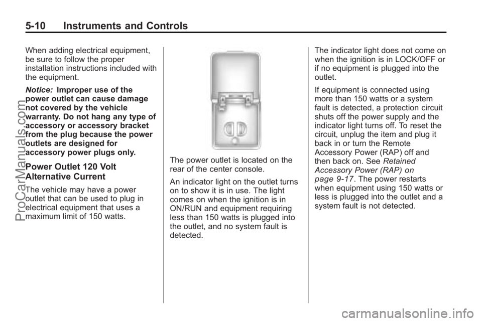
The power outlet is located on the
rear of the center console.
An indicator light on the outlet turns
on to show it is in use. The light
comes on when the ignition is in
ON/RUN and equipment requiring
less than 150 watts is plugged into
the outlet, and no system fault is
detected. The indicator light does not come on
when the ignition is in LOCK/OFF or
if no equipment is plugged into the
outlet.
If equipment is connected using
more than 150 watts or a system
fault is detected, a protection circuit
shuts off the power supply and the
indicator light turns off. To reset the
circuit, unplug the item and plug it
back in or turn the Remote
Accessory Power (RAP) off and
then back on. See
Retained
Accessory Power (RAP)
on
page 9‑17. The power restarts
when equipment using 150 watts or
less is plugged into the outlet and a
system fault is not detected.
ProCarManuals.com
Page 143 of 444
Instruments and Controls 5-21
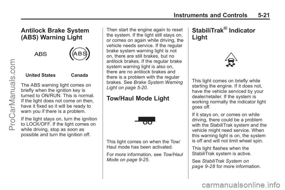
Antilock Brake System
(ABS) Warning Light
United StatesCanada
The ABS warning light comes on
briefly when the ignition key is
turned to ON/RUN. This is normal.
If the light does not come on then,
have it fixed so it will be ready to
warn you if there is a problem.
If the light stays on, turn the ignition
to LOCK/OFF. If the light comes on
while driving, stop as soon as
possible and turn the ignition off. Then start the engine again to reset
the system. If the light still stays on,
or comes on again while driving, the
vehicle needs service. If the regular
brake system warning light is not
on, there are still brakes, but no
antilock brakes. If the regular brake
system warning light is also on,
there are no antilock brakes and
there is a problem with the regular
brakes. See
Brake System Warning
Light on page 5‑20.
Tow/Haul Mode Light
This light comes on when the Tow/
Haul mode has been activated.
For more information, see Tow/Haul
Mode on page 9‑25.
StabiliTrak®Indicator
Light
This light comes on briefly while
starting the engine. If it does not,
have the vehicle serviced by your
dealer/retailer. If the system is
working normally the indicator light
goes off.
If it stays on, or comes on while
driving, there could be a problem
with the StabiliTrak system and the
vehicle might need service. When
this warning light is on, the system
is off and will not limit wheel spin.
This light flashes when the
StabiliTrak system is active.
See StabiliTrak System
on
page 9‑28for more information.
ProCarManuals.com