display SATURN VUE 2009 Owners Manual
[x] Cancel search | Manufacturer: SATURN, Model Year: 2009, Model line: VUE, Model: SATURN VUE 2009Pages: 386, PDF Size: 2.3 MB
Page 68 of 386

Remote Keyless Entry
(RKE) System Operation
The Remote Keyless Entry (RKE)
transmitter functions work up to
195 feet (60 m) away from the
vehicle.
There are other conditions which
can affect the performance of the
transmitter. SeeRemote Keyless
Entry (RKE) System on page 2-3.
/(Remote Vehicle Start):
For vehicles with this feature, this
button is used to operate the remote
start feature. SeeRemote Vehicle
Start on page 2-5for additional
information.
Q(Lock):Press to lock all the
doors, including the liftgate.
K(Unlock):Press once to unlock
the driver door. If
Kis pressed again
within �ve seconds, all remaining
doors unlock. The interior lamps
come on and stay on for 20 seconds
or until the ignition is turned on.
L(Vehicle Locator/Panic Alarm):
Press and release to locate the
vehicle. The turn signal lamps �ash
and the horn sounds three times.
Press and hold
Lto activate the
panic alarm. The turn signal lamps
�ash and the horn sounds repeatedly
for 30 seconds. The alarm turnsoff when the ignition is turned to
ON/RUN or when
Lis pressed
again. The ignition must be in
LOCK/OFF for the panic alarm
to work.
Programming Transmitters
to the Vehicle
Only RKE transmitters
programmed to the vehicle
will work. If a transmitter is lost
or stolen, a replacement can be
purchased and programmed
through your dealer/retailer.
When the replacement transmitter
is programmed to the vehicle, all
remaining transmitters must also
be programmed. Any lost or stolen
transmitters no longer work once
the new transmitter is programmed.
Each vehicle can have up to eight
transmitters programmed to it.
See “Relearn Remote Key” under
DIC Operation and Displays on
page 3-42. Without Remote Start Shown
(With Remote Start Similar)
2-4 Features and Controls
ProCarManuals.com
Page 69 of 386

Battery Replacement
Replace the battery if the
REPLACE REMOTE KEY FOB
BATTERY message displays on
the Driver Information Center (DIC).
See “REPLACE REMOTE KEY FOB
BATTERY” underDIC Warnings and
Messages on page 3-49.
Notice:When replacing the
battery, do not touch any of the
circuitry on the transmitter. Static
from your body could damage
the transmitter.To replace the battery:
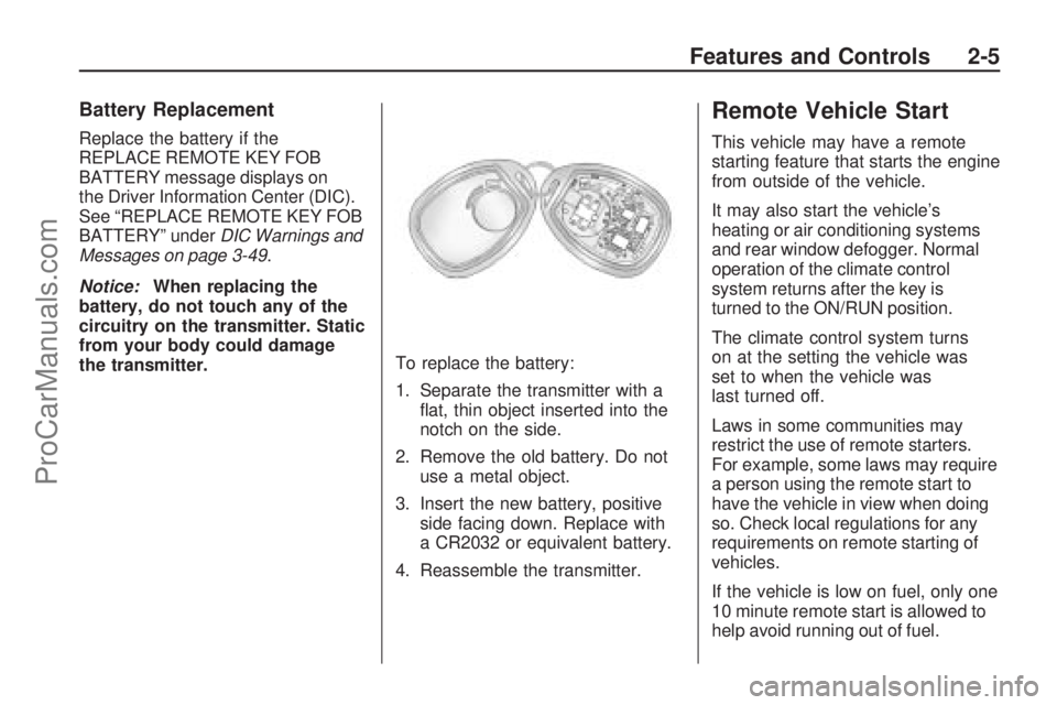
1. Separate the transmitter with a
�at, thin object inserted into the
notch on the side.
2. Remove the old battery. Do not
use a metal object.
3. Insert the new battery, positive
side facing down. Replace with
a CR2032 or equivalent battery.
4. Reassemble the transmitter.
Remote Vehicle Start
This vehicle may have a remote
starting feature that starts the engine
from outside of the vehicle.
It may also start the vehicle’s
heating or air conditioning systems
and rear window defogger. Normal
operation of the climate control
system returns after the key is
turned to the ON/RUN position.
The climate control system turns
on at the setting the vehicle was
set to when the vehicle was
last turned off.
Laws in some communities may
restrict the use of remote starters.
For example, some laws may require
a person using the remote start to
have the vehicle in view when doing
so. Check local regulations for any
requirements on remote starting of
vehicles.
If the vehicle is low on fuel, only one
10 minute remote start is allowed to
help avoid running out of fuel.
Features and Controls 2-5
ProCarManuals.com
Page 80 of 386

Ignition Positions
The ignition switch has four different
positions.
To shift out of P (Park), turn the
ignition to ON/RUN and apply
the regular brake pedal.
Notice:Using a tool to force the
key to turn in the ignition could
cause damage to the switch or
break the key. Use the correct key,
make sure it is all the way in, and
turn it only with your hand. If the
key cannot be turned by hand,
see your dealer/retailer.LOCK/OFF:This position locks the
ignition. It also locks the steering
wheel and the transmission. The key
can only be removed in LOCK/OFF.
The shift lever must be in P (Park)
to turn the ignition switch to
LOCK/OFF.
The steering can bind with the
wheels turned off center. If this
happens, move the steering wheel
from right to left while turning the key
to ACC/ACCESSORY. If this doesn’t
work, the vehicle needs service.
ACC (ACC/ACCESSORY):This is
the position in which you can operate
the electrical accessories or items
plugged into the accessory power
outlets.
Use this position if the vehicle must
be pushed or towed.ON/RUN:This position can be used
to operate the electrical accessories
and to display some instrument
panel cluster warning and indicator
lights. The switch stays in this
position when the engine is running.
The transmission is also unlocked in
this position. If you leave the key in
the ACC/ACCESSORY or ON/RUN
positions with the engine off, the
battery could be drained. You may
not be able to start the vehicle if the
battery is allowed to drain for an
extended period of time.
START:This is the position that
starts the engine. When the engine
starts, release the key. The ignition
switch returns to ON/RUN for driving.
A warning tone will sound when the
driver door is opened, the ignition is
in ACC/ACCESSORY or LOCK/OFF
and the key is in the ignition.
2-16 Features and Controls
ProCarManuals.com
Page 85 of 386

Manual Shift Mode (MSM)
(Automatic Transmission)
To use this feature, do the following:
1. Move the shift lever from
D (Drive) to the left into the
manual gate.
While driving in manual
shift mode, the transmission
will remain in the driver gear
selected. When coming to a
stop in the manual position,
the vehicle will automatically
shift to 1 (First) gear.
2. Push the shift lever forward
toward the plus (+) to upshift or
rearward toward the minus (−)to
downshift. The instrument panel
will display the actual gear
selected.
In manual shift mode all six forward
gears can be selected.While using the MSM feature the
vehicle will have operation similar to
a manual transmission. You can use
this for sport driving or when driving
hilly roads to stay in gear longer or to
downshift for more power or engine
braking.
The transmission will only allow you
to shift into gears appropriate for
the vehicle speed:
The transmission will not
automatically shift to the next
higher gear without moving
the shift lever.
The transmission will not allow
shifting to the next lower gear
if the vehicle speed is too high.
If the vehicle does not respond to a
gear change, or detects a problem
with the transmission, the range of
gears may be reduced and the
Malfunction Indicator Lamp will come
on. SeeMalfunction Indicator Lamp
on page 3-35.
2 (Second) and 3 (Third) Gear
Start Feature
When accelerating the vehicle from
a stop in snowy and icy conditions,
you may want to select 2 (Second)
and 3 (Third) gear. A higher gear,
and light application of the gas pedal,
may allow you to gain more traction
on slippery surfaces.
With the Manual Shift Mode, the
vehicle can accelerate from a stop
in 2 (Second) or 3 (Third).
1. Move the shift lever from
D (Drive) into the manual gate.
2. With the vehicle stopped,
move the shift lever forward to
select 2 (Second) or 3 (Third).
The vehicle will start from a
stop position in 2 (Second)
or 3 (Third).
3. Once the vehicle is moving
select the desired drive gear
or move the shift lever to
the D (Drive) position.
Features and Controls 2-21
ProCarManuals.com
Page 88 of 386

Manual Shift Mode (MSM)
(Automatic Transmission)
To use this feature, do the following:
1. Move the shift lever from
D (Drive) rearward to M (Manual).
The six-speed transmission will
downshift to a lower gear and the
instrument panel will display the
gear range selected. If equipped
with a 4-speed transmission it will
display a 3 for third gear range.
When coming to a stop in
the manual position, the vehicle
will automatically shift to
1 (First) gear.
2. Press the plus (+) button to
upshift or the minus (−) button
to downshift.While using the MSM feature
the vehicle will have sportier
performance. You can use this
when driving hilly roads to stay
in gear longer or to downshift for
more power or engine braking.
The transmission will only allow you
to shift into a gear range appropriate
for the vehicle speed.
The transmission will not
automatically shift to the next
higher gear range without
pressing the button on the
shifter handle.
The transmission will not allow
shifting to the next lower gear if
the vehicle speed is too high.
If the vehicle does not respond
to a gear change, or detects a
problem with the transmission, the
range of gears may be reduced and
the Malfunction Indicator Lamp will
come on. SeeMalfunction Indicator
Lamp on page 3-35.
Parking Brake
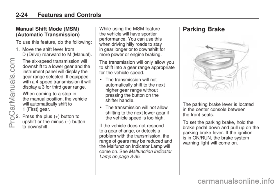
The parking brake lever is located
in the center console between
the front seats.
To set the parking brake, hold the
brake pedal down and pull up on the
parking brake lever. If the ignition
is in ON/RUN, the brake system
warning light will come on.
2-24 Features and Controls
ProCarManuals.com
Page 95 of 386

Object Detection
Systems
Rear Vision
Camera (RVC)
The vehicle may have a Rear Vision
Camera system. Read this entire
section before using it.
{CAUTION
The Rear Vision Camera (RVC)
system does not replace driver
vision. RVC does not:
Detect objects that are
outside the camera’s �eld
of view, below the bumper,
or underneath the vehicle.
Detect children, pedestrians,
bicyclists, or pets.
(Continued)
CAUTION (Continued)
Do not back the vehicle by only
looking at the rear vision camera
screen, or use the screen during
longer, higher speed backing
maneuvers or where there could
be cross-traffic. Your judged
distances using the screen will
differ from actual distances.
So if you do not use proper care
before backing up, you could hit a
vehicle, child, pedestrian, bicyclist,
or pet, resulting in vehicle damage,
injury, or death. Even though the
vehicle has the RVC system,
always check carefully before
backing up by checking behind
and around the vehicle.
The rear vision camera system is
designed to help the driver when
backing up by displaying a view of
the area behind the vehicle.When the key is in the ON/RUN
position and the driver shifts the
vehicle into R (Reverse), the video
image automatically appears on the
inside rear view mirror. Once the
driver shifts out of R (Reverse),
the video image automatically
disappears from the inside rear
view mirror.
Turning the Rear Vision Camera
System Off or On
To turn off the rear vision camera
system, press and hold
z, located
on the inside rearview mirror, until
the left indicator light turns off.
The rear vision camera display
is now disabled.
To turn the rear vision camera
system on again, press and
hold
zuntil the left indicator light
illuminates. The rear vision camera
system display is now enabled and
the display will appear in the mirror
normally.
Features and Controls 2-31
ProCarManuals.com
Page 96 of 386

Rear Vision Camera Location
The camera is located in the
rear of the vehicle.
The area displayed by the
camera is limited and does not
display objects that are close to
either corner or under the bumper.
The area displayed can vary
depending on vehicle orientation or
road conditions. The distance of the
image that appears on the screen
differs from the actual distance.
The following illustration shows
the �eld of view that the camera
provides.
A. View displayed by the camera.
B. Corner of the rear bumper.
When the System Does Not
Seem To Work Properly
The rear vision camera system
might not work properly or display
a clear image if:
The RVC is turned off.
See “Turning the Rear
Camera System On or Off”
earlier in this section.
It is dark.
The sun or the beam of
headlights is shining directly
into the camera lens.
Ice, snow, mud, or anything else
builds up on the camera lens.
Clean the lens, rinse it with water,
and wipe it with a soft cloth.
2-32 Features and Controls
ProCarManuals.com
Page 97 of 386

The back of the vehicle is in
an accident, the position and
mounting angle of the camera
can change or the camera can
be affected. Be sure to have the
camera and its position and
mounting angle checked at your
dealer/retailer.
There are extreme temperature
changes.
The rear vision camera system
display in the rearview mirror may
turn off or not appear as expected
due to one of the following
conditions. If this occurs the left
indicator light on the mirror will �ash.
A slow �ash may indicate a loss of
video signal, or no video signal
present during the reverse cycle.
A fast �ash may indicate that
the display has been on for the
maximum allowable time during a
reverse cycle, or the display has
reached an Over Temperature
limit.
The fast �ash conditions are used
to protect the video device from
high temperature conditions.
Once conditions return to normal
the device will reset and the green
indicator will stop �ashing.
During any of these fault conditions,
the display will be blank and the
indicator will continue to �ash as long
as the vehicle is in R (Reverse) or
until the conditions return to normal.
Pressing and holding
zwhen the
left indicator light is �ashing will turn
off the video display along with
the left indicator light.
OnStar®System
OnStar uses several innovative
technologies and live advisors to
provide a wide range of safety,
security, information, and
convenience services. If the airbags
deploy, the system is designed to
make an automatic call to OnStar
Emergency advisors who can
request emergency services be sent
to your location. If the keys are
locked in the vehicle, call OnStar at
1-888-4-ONSTAR to have a signal
sent to unlock the doors. OnStar
Hands-Free Calling, including
30 trial minutes good for 60 days, is
available on most vehicles. OnStar
Turn-by-Turn Navigation service,
with one trial route, is available on
most vehicles. Press the OnStar
button to have an OnStar advisor
contact Roadside Service.
Features and Controls 2-33
ProCarManuals.com
Page 112 of 386

Engine Coolant Temperature
Warning Light....................3-34
Tire Pressure Light..............3-34
Malfunction
Indicator Lamp..................3-35
Oil Pressure Light................3-37
Change Engine Oil Light.......3-38
Security Light......................3-38
Fog Lamp Light...................3-38
Cruise Control Light.............3-38
Reduced Engine
Power Light......................3-39
Highbeam On Light..............3-39
Daytime Running Lamps
(DRL) Indicator Light..........3-39
Low Washer Fluid
Warning Light....................3-40
All-Wheel Drive
Disabled Light...................3-40
Gate Ajar Light....................3-40
Door Ajar Light....................3-40
Service Vehicle Soon Light.....3-40
Fuel Gage..........................3-41
Low Fuel Warning Light........3-41Driver Information
Center (DIC)
Driver Information
Center (DIC).....................3-42
DIC Operation and Displays. . .3-42
DIC Compass.....................3-47
DIC Warnings and
Messages.........................3-49
DIC Vehicle Customization.....3-57
Audio System(s)Audio System(s)..................3-64
Setting the Clock.................3-65
Radio(s).............................3-67
Using an MP3.....................3-75
XM Radio Messages............3-79
Navigation/Radio System......3-81
Bluetooth
®..........................3-81
Theft-Deterrent Feature........3-91
Audio Steering Wheel
Controls............................3-92
Radio Reception..................3-92
Fixed Mast Antenna.............3-93
XM™ Satellite Radio
Antenna System................3-93
Chime Level Adjustment.......3-93
3-2 Instrument Panel
ProCarManuals.com
Page 125 of 386

Reading Lamps
The reading lamps are located on
the overhead console.
To turn the reading lamps on or off,
press the button located next to
each lamp.
Electric Power
Management
The vehicle has Electric Power
Management (EPM) that estimates
the battery’s temperature and state
of charge. It then adjusts the voltage
for best performance and extended
life of the battery.
When the battery’s state of charge is
low, the voltage is raised slightly to
quickly bring the charge back up.
When the state of charge is high,
the voltage is lowered slightly to
prevent overcharging. If the vehicle
has a voltmeter gage or a voltage
display on the Driver InformationCenter (DIC), you may see the
voltage move up or down. This is
normal. If there is a problem, an alert
will be displayed.
The battery can be discharged at
idle if the electrical loads are very
high. This is true for all vehicles. This
is because the generator (alternator)
may not be spinning fast enough at
idle to produce all the power that is
needed for very high electrical loads.
A high electrical load occurs when
several of the following are on,
such as: headlamps, high beams,
fog lamps, rear window defogger,
climate control fan at high speed,
heated seats, engine cooling fans,
trailer loads, and loads plugged into
accessory power outlets.
EPM works to prevent excessive
discharge of the battery. It does this
by balancing the generator’s output
and the vehicle’s electrical needs.It can increase engine idle speed to
generate more power, whenever
needed. It can temporarily reduce
the power demands of some
accessories.
Normally, these actions occur
in steps or levels, without being
noticeable. In rare cases at the
highest levels of corrective action,
this action may be noticeable to the
driver. If so, a Driver Information
Center (DIC) message might be
displayed, such as BATTERY
SAVER ACTIVE, BATTERY
VOLTAGE LOW, or LOW BATTERY.
If this message is displayed, it is
recommended that the driver reduce
the electrical loads as much as
possible. SeeDIC Warnings and
Messages on page 3-49.
Instrument Panel 3-15
ProCarManuals.com