Seat Alhambra 2008 Repair Manual
Manufacturer: SEAT, Model Year: 2008, Model line: Alhambra, Model: Seat Alhambra 2008Pages: 295, PDF Size: 7.83 MB
Page 61 of 295
59
Safety First
Operating instructions
Tips and Maintenance
Te c h n i c a l D a t a
alhambra_ingles_0708 Seite 59 Mittwoch, 10. September 2008 10:55 10
Page 62 of 295
60
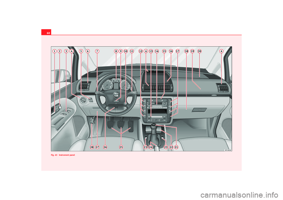
Fig. 43 Instrument panelalhambra_ingles_0708 Seite 60 Mittwoch, 10. September 2008 10:55 10
Page 63 of 295
Cockpit61
Safety First
Operating instructions
Tips and Maintenance
Te c h n i c a l D a t a
Operating instructionsCockpitOverviewOverview of the instrument panel
This overview will help you to familiarise yourself with the
controls and displays.
Door release lever . . . . . . . . . . . . . . . . . . . . . . . . . . . . . . . . . . .
Electric wing mirror adjustment control . . . . . . . . . . . . . . . . . . .
Electric window control . . . . . . . . . . . . . . . . . . . . . . . . . . . . . . . .
Light switch . . . . . . . . . . . . . . . . . . . . . . . . . . . . . . . . . . . . . . . . .
Instrument lighting control / Headlamp range control . . . . . . .
Air outlets
main beam and turn signal light lever/ Cruise control* / . . . . .
Instrument panel / warning lights / . . . . . . . . . . . . . . . . . . . . . .
Horn / Driver's airbag* . . . . . . . . . . . . . . . . . . . . . . . . . . . . . . . .
Ignition lock . . . . . . . . . . . . . . . . . . . . . . . . . . . . . . . . . . . . . . . . .
Windscreen wiper lever . . . . . . . . . . . . . . . . . . . . . . . . . . . . . . . .
Switches for:
−rear window heater . . . . . . . . . . . . . . . . . . . . . . . . . . . . . . . . .
− windscreen heater* . . . . . . . . . . . . . . . . . . . . . . . . . . . . . . . .
− left seat heating* . . . . . . . . . . . . . . . . . . . . . . . . . . . . . . . . . .
− ESP* . . . . . . . . . . . . . . . . . . . . . . . . . . . . . . . . . . . . . . . . . . . . .
Climatronic . . . . . . . . . . . . . . . . . . . . . . . . . . . . . . . . . . . . . . . . .
Radio Cup holder* . . . . . . . . . . . . . . . . . . . . . . . . . . . . . . . . . . . . . . . . .
Central upper stowage compartment . . . . . . . . . . . . . . . . . . . .
Switches for:
−
hazard warning light switch . . . . . . . . . . . . . . . . . . . . . . . . . .
− PDC* (parking distance control) . . . . . . . . . . . . . . . . . . . . . .
− right seat heating* . . . . . . . . . . . . . . . . . . . . . . . . . . . . . . . . .
− cover for supplementary switch
Glove box/Stowage compartment . . . . . . . . . . . . . . . . . . . . . . .
Passenger airbag* . . . . . . . . . . . . . . . . . . . . . . . . . . . . . . . . . . .
Passenger side upper stowage compartment . . . . . . . . . . . . . .
Gear lever . . . . . . . . . . . . . . . . . . . . . . . . . . . . . . . . . . . . . . . . . . .
Ash tray/ lighter . . . . . . . . . . . . . . . . . . . . . . . . . . . . . . . . . . . . .
Electric side window controls* . . . . . . . . . . . . . . . . . . . . . . . . . .
Handbrake . . . . . . . . . . . . . . . . . . . . . . . . . . . . . . . . . . . . . . . . . .
Pedals
Steering control adjustment lever* . . . . . . . . . . . . . . . . . . . . . .
Fusebox cover . . . . . . . . . . . . . . . . . . . . . . . . . . . . . . . . . . . . . . .
Unlock bonnet lever . . . . . . . . . . . . . . . . . . . . . . . . . . . . . . . . . .
Note
•
Some of the items of equipment listed here are fitted only on certain
models/model years or are optional extras.
•
In versions with the steering wheel on the right, the layout of the control
elements is somewhat different. But the symbols assigned to the controls
A1
92
A2
119
A3
101
A4
109
A5
109
A6A7
111, 176
A8
62, 70
A9
36
A10
162
A11
116
A12
115
115
125
182
A13
152
A14
A15
136
A16
134
A17
110
174
125
A18
134
A19
36
A20
133
A21
166
A22
139
A23
101
A24
173
A25A26
160
A27
241
A28
211
alhambra_ingles_0708 Seite 61 Mittwoch, 10. September 2008 10:55 10
Page 64 of 295
Cockpit
62correspond to the symbols used in the versions with the steering wheel on
the leftInstrumentsInstrument overview
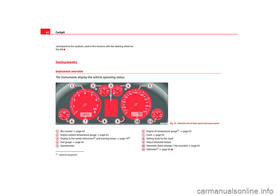
The instruments display the vehicle operating status.
Rev counter ⇒page 63
Engine coolant temperature gauge ⇒ page 63
Display in the combi-instrument
4) and warning lamps ⇒page 70
4)
Fuel gauge ⇒ page 64
Speedometer Engine oil temperature gauge
4)
⇒ page 65
Clock ⇒page 65
Setting knob for the clock
Adjust kilometre button
Odometer (total mileage / trip recorder) ⇒page 65
Vo ltm e te r
4) ⇒ page 65
Fig. 44 Detailed view of dash panel instrument panel
4)Optional equipmentA1A2A3A4A5
A6A7A8A9A10A11
alhambra_ingles_0708 Seite 62 Mittwoch, 10. September 2008 10:55 10
Page 65 of 295
Cockpit63
Safety First
Operating instructions
Tips and Maintenance
Te c h n i c a l D a t a
Rev counter
The rev. counter displays the engine speed in revolutions per
minute.If, for example, the needle is directly over the 2, this corresponds to an engine
speed of 2000 rpm (revolutions per minute) ⇒page 62, fig. 44 .
The start of the red zone on the dial indicates the maximum engine speed
which may be used briefly when the engine is warm and after it has been run
in properly. However, it is advisable to change up a gear or move the selector
lever to D (or lift your foot off the accelerator) before the needle reaches the
red zone.
Caution
The rev counter needle must never enter the red zone on the scale. Risk of
engine damage.
For the sake of the environment
Changing up a gear early will help you to save fuel and minimise engine
noise.
Engine coolant temperature display
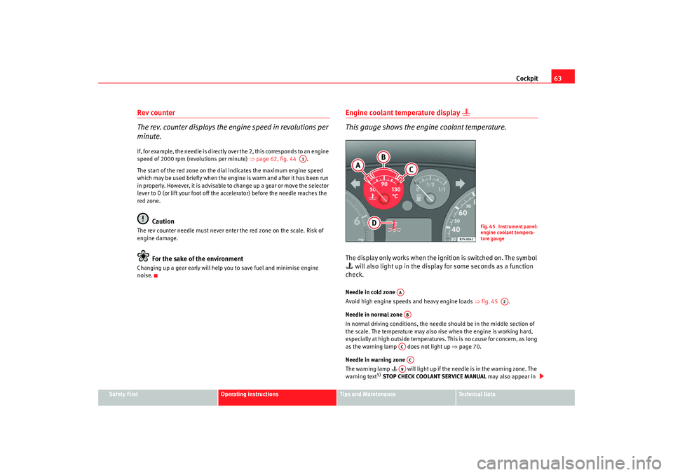
This gauge shows the engine coolant temperature.The display only works when the ignition is switched on. The symbol will also light up in the display for some seconds as a function
check.Needle in cold zone
Avoid high engine speeds and heavy engine loads ⇒fig. 45 .
Needle in normal zone
In normal driving conditions, the needle should be in the middle section of
the scale. The temperature may also rise when the engine is working hard,
especially at high outside temperatures. This is no cause for concern, as long
as the warning lamp does not light up ⇒page 70.
Needle in warning zone
The warning lamp will light up if the needle is in the warning zone. The
warning text
5) STOP CHECK COOLANT SERVICE MANUAL may also appear in
A1
Fig. 45 Instrument panel:
engine coolant tempera-
ture gauge
AA
A2
ABACAC
A9
alhambra_ingles_0708 Seite 63 Mittwoch, 10. September 2008 10:55 10
Page 66 of 295
Cockpit
64the combi-instrument display. Stop the car and switch off the engine. Allow
the engine to cool and check the coolant level ⇒.
Even if the coolant level is correct do not continue driving . You should obtain
technical assistance.
WARNING
Read and observe the warnings “Working in the engine compartment”
before opening the bonnet to carry out work in the engine compartment.
Caution
Accessories in front of the air inlet reduce the cooling effect of the coolant. At
high outside temperatures and high engine loads, there is a risk of the
engine overheating.
Fuel gauge
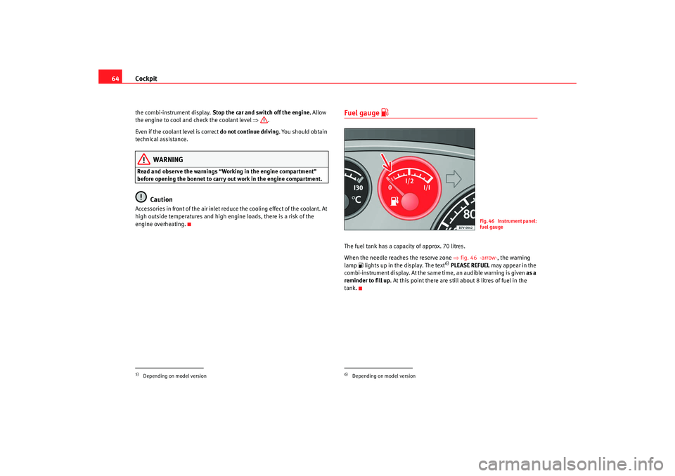
The fuel tank has a capacity of approx. 70 litres.
When the needle reaches the reserve zone ⇒fig. 46 -arrow- , the warning
lamp lights up in the display. The text
6) PLEASE REFUEL may appear in the
combi-instrument display. At the same time, an audible warning is given as a
reminder to fill up. At this point there are still about 8 litres of fuel in the
tank.
5)Depending on model version
6)Depending on model version
F i g . 4 6 I n s t r u m e n t p a n e l :
fuel gauge
alhambra_ingles_0708 Seite 64 Mittwoch, 10. September 2008 10:55 10
Page 67 of 295
Cockpit65
Safety First
Operating instructions
Tips and Maintenance
Te c h n i c a l D a t a
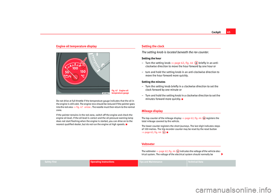
Engine oil temperature displayDo not drive at full throttle if the temperature gauge indicates that the oil in
the engine is still cold. The engine revs should be reduced if the pointer goes
into the red area ⇒fig. 47 -arrow- . The needle must then return to the normal
zone.
If the pointer remains in the red zone, switch off the engine and check the
engine oil level. If the oil level is correct and the oil pressure warning lamp
does not start flashing when the engine is started, you can drive on to the
nearest qualified dealer, but do not run the engine at high speeds.
Setting the clock
The setting knob is located beneath the rev counter.Setting the hour
– Turn the setting knob ⇒ page 62, fig. 44 briefly in an anti-
clockwise direction to move the hour forward by one hour or
– turn and hold the setting knob in an anti-clockwise direction to move the hour forward more quickly.
Setting the minutes
– Turn the setting knob briefly in a clockwise direction to set the clock forward by one minute or
– Turn and hold the setting knob in a clockwise direction to set the minutes forward more quickly.Mileage displayThe top counter of the mileage display ⇒page 62, fig. 44 registers the
total mileage covered by the vehicle.
The lower counter registers the short journeys. The last digit indicates steps
of 100 metres. The trip recorder counter may be reset by the reset button
⇒ page 62, fig. 44 .Voltmeter The voltmeter ⇒page 62, fig. 44 indicates the voltage of the vehicle elec-
trical system. The voltage of the electrical system should normally be
Fig. 47 Engine oil
temperature gauge
A8
A10
A9
A11
alhambra_ingles_0708 Seite 65 Mittwoch, 10. September 2008 10:55 10
Page 68 of 295
Cockpit
66between 12 and 15 volts. If the voltage drops below 12 volts when the engine
is running, you should have the power supply (battery and alternator)
checked by a qualified dealership.
Note
The voltage may drop below 8 volts while the engine is being started.Service Interval Display The service display is shown either on the mileage display ⇒page 62, fig. 44
or in the display
7) in the combi-instrument ⇒ page 62, fig. 44 .
Service warning
A service pre-warning will appear in the odometer if a service is due soon. A
spanner symbol
appears in the display along with the miles and the
number of kilometres until the next service. The service message will disap-
pear approximately 20 seconds after the ignition is switched on or if the
engine is running.
The distance quoted to the next scheduled service is reduced in increments
of 100 miles.
The following information text displayed in the instrument panel display:
SERVICE IN... KM OR SERVICE IN... DAYS . The service message will disappear
approximately 20 seconds after the ignition is switched on or the engine is
running. The normal display can be resumed by pressing the reset button on
the trip counter or by pressing the rocker switch of the windscreen wiper lever .
If a service is due , a gong signal will sound and the flashing “spanner”
symbol will appear for approximately 20 seconds. The following information
text displayed in the instrument panel display: SERVICE NOW. With the ignition switched on, you can call up the current service message
by
pressing the trip counter reset knob for 2 seconds.
An overdue service is indicated by a minus sign in front of the mileage or day
information.
Resetting the service display
The display is reset by the SEAT dealer after the service has been carried out.
You will receive a print-out from the SEAT dealership as confirmation that this
work has been carried out.
If the service is not carried out by a SEAT Service centre, the service interval
display will have to be reset manually as follows:
•
Switch off ignition.
•
Press and hold the reset knob for the trip meter.
•
Turn the ignition on and turn the reset button to the right. The display will
return to the normal mode.Note
•
The next service will be displayed after 15,000 km (10,000 miles) if you
reset the service display yourself. The service interval will not be determined
individually.
•
Do not reset the display between service intervals as the display will
otherwise be incorrect.
7)Optional equipmentA10
A3
AB
alhambra_ingles_0708 Seite 66 Mittwoch, 10. September 2008 10:55 10
Page 69 of 295
Cockpit67
Safety First
Operating instructions
Tips and Maintenance
Te c h n i c a l D a t a
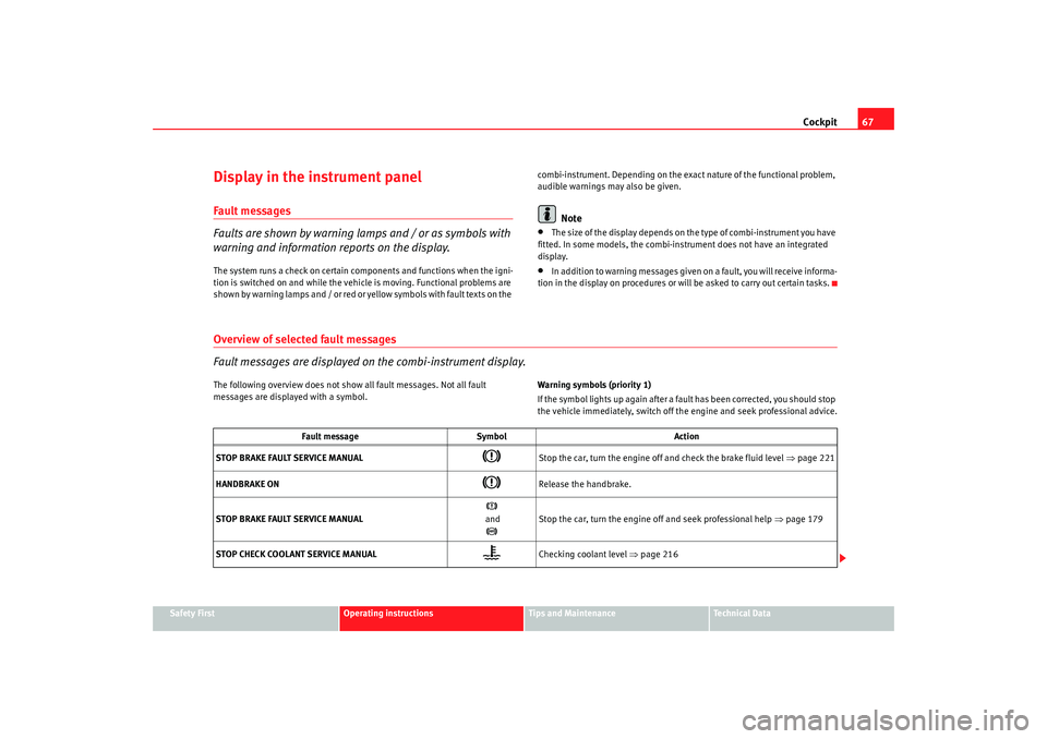
Display in the instrument panel Fault messages
Faults are shown by warning lamps and / or as symbols with
warning and information reports on the display.The system runs a check on certain components and functions when the igni-
tion is switched on and while the vehicle is moving. Functional problems are
shown by warning lamps and / or red or yellow symbols with fault texts on the combi-instrument. Depending on the exact nature of the functional problem,
audible warnings may also be given.
Note
•
Th e size o f t h e d isp l ay d e p en ds on th e ty p e o f com b i - ins tr u m e n t y ou h av e
fitted. In some models, the combi-instrument does not have an integrated
display.
•
In addition to warning messages given on a fault, you will receive informa-
tion in the display on procedures or will be asked to carry out certain tasks.
Overview of selected fault messages
Fault messages are displayed on the combi-instrument display.The following overview does not show all fault messages. Not all fault
messages are displayed with a symbol. Warning symbols (priority 1)
If the symbol lights up again after a fault has been corrected, you should stop
the vehicle immediately, switch off the engine and seek professional advice.
Fault message
Symbol Action
STOP BRAKE FAULT SERVICE MANUAL
Stop the car, turn the engine off and check the brake fluid level ⇒page 221
HANDBRAKE ON
Release the handbrake.
STOP BRAKE FAULT SERVICE MANUAL
and
Stop the car, turn the engine off and seek professional help ⇒page 179
STOP CHECK COOLANT SERVICE MANUAL
Checking coolant level ⇒ page 216
alhambra_ingles_0708 Seite 67 Mittwoch, 10. September 2008 10:55 10
Page 70 of 295
Cockpit
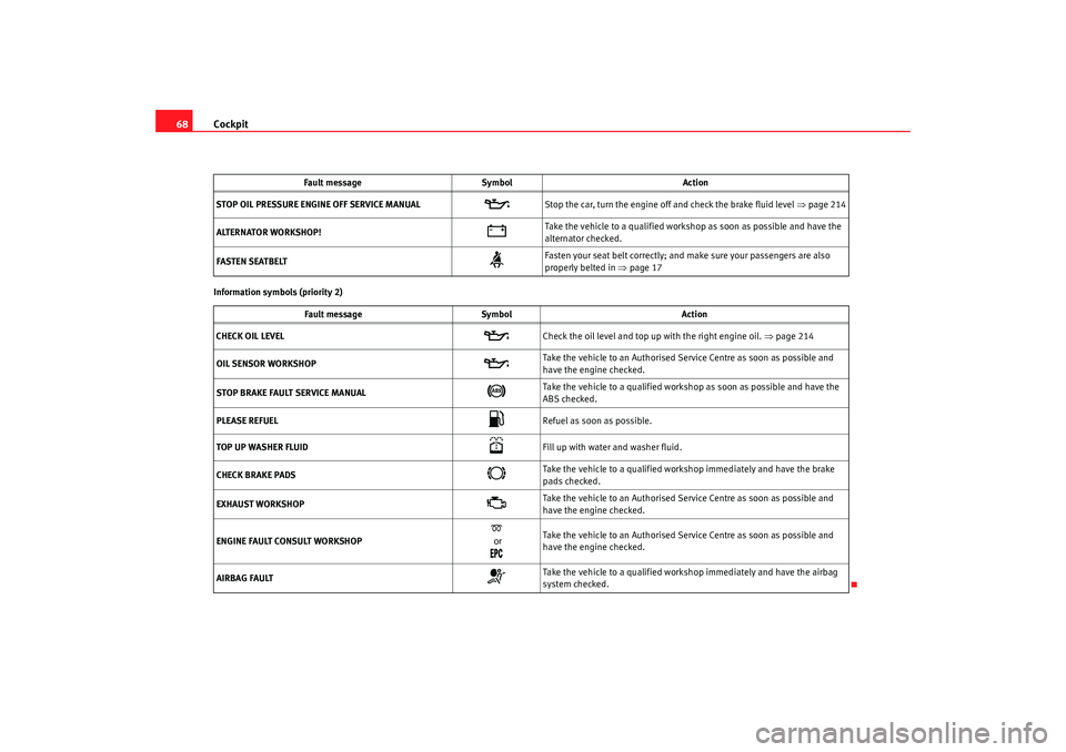
68Information symbols (priority 2) STOP OIL PRESSURE ENGINE OFF SERVICE MANUAL
Stop the car, turn the engine off and check the brake fluid level ⇒page 214
ALTERNATOR WORKSHOP!
Take the vehicle to a qualified workshop as soon as possible and have the
alternator checked.
FASTEN SEATBELT
Fasten your seat belt correctly; and make sure your passengers are also
properly belted in ⇒page 17
Fault message Symbol Action
CHECK OIL LEVEL
Check the oil level and top up with the right engine oil. ⇒page 214
OIL SENSOR WORKSHOP
Take the vehicle to an Authorised Service Centre as soon as possible and
have the engine checked.
STOP BRAKE FAULT SERVICE MANUAL
Take the vehicle to a qualified workshop as soon as possible and have the
ABS checked.
PLEASE REFUEL
Refuel as soon as possible.
TOP UP WASHER FLUID
Fill up with water and washer fluid.
CHECK BRAKE PADS
Take the vehicle to a qualified workshop immediately and have the brake
pads checked.
EXHAUST WORKSHOP
Take the vehicle to an Authorised Service Centre as soon as possible and
have the engine checked.
ENGINE FAULT CONSULT WORKSHOP
or
Take the vehicle to an Authorised Service Centre as soon as possible and
have the engine checked.
AIRBAG FAULT
Take the vehicle to a qualified workshop immediately and have the airbag
system checked.
Fault message
Symbol Action
alhambra_ingles_0708 Seite 68 Mittwoch, 10. September 2008 10:55 10