remote control Seat Alhambra 2017 Owner's Manual
[x] Cancel search | Manufacturer: SEAT, Model Year: 2017, Model line: Alhambra, Model: Seat Alhambra 2017Pages: 320, PDF Size: 6.88 MB
Page 10 of 320
The essentials
How it works
Un loc
k
ing and locking
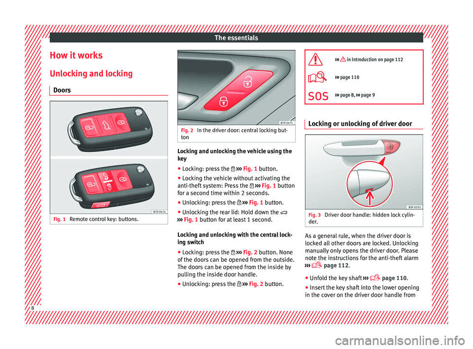
Doors Fig. 1
Remote control key: buttons. Fig. 2
In the driver door: central locking but-
ton Locking and unlocking the vehicle using the
k
ey
â Loc
king: press the ï½ âºâºâº
Fig. 1 button.
â Locking the vehicle without activating the
anti-theft sy
stem: Press the ï½ âºâºâº Fig. 1 button
for a second time within 2 seconds.
â Unlocking: press the ï¼ âºâºâº
Fig. 1 button.
â Unlocking the rear lid: Hold down the ï²
âºâºâº
Fig. 1 button for at least 1 second.
Locking and unlocking with the central lock-
ing switch
â Locking: press the ï½ âºâºâº
Fig. 2 button. None
of the doors can be opened from the outside.
The doors can be opened from the inside by
pulling the inside door handle.
â Unlocking: press the ï¼ âºâºâº
Fig. 2 button. ïª
âºâºâº in Introduction on page 112
ï©âºâºâº
page 110
ïªâºâºâº page 8, âºâºâº page 9 Locking or unlocking of driver door
Fig. 3
Driver door handle: hidden lock cylin-
der . As a general rule, when the driver door is
loc
k
ed al
l other doors are locked. Unlocking
manually only opens the driver door. Please
note the instructions for the anti-theft alarm
âºâºâº ï© page 112.
â Unfold the key shaft âºâºâº
ï© page 110.
â Insert the key shaft into the lower opening
in the cov
er on the driver door handle from8
Page 33 of 320
The essentials
Submenu ConvenienceCentral lock-
ing
âºâºâº page 112
Auto. lock (Auto Lock): automatic
locking of all doors and boot when
reaching a speed of approximately
15 km/h (10 mph). In order to unlock
the vehicle when it is stopped, push the
central locking button, pull the door
handle or remove the key from the igni-
tion lock if the Auto unlock function
is enabled.
Auto unlock (Auto Lock): Unlocking
all doors and the boot by removing the
ignition lock key.
Door unlock : when unlocking the ve-
hicle with the key, the following doors
will unlock based on the setting:
â All : all of the doors are unlocked.
â One door : when unlocking the vehi-
cle with the key, only the driver's door
unlocks. Pressing the button
ï again
unlocks all doors and the boot.
â Vehicle side : the doors on the
driver's side unlock.
On vehicles fitted with the Keyless
Access âºâºâº page 112 system, when using
the corresponding handle, all doors un-
lock on the side of the vehicle where the
key is.
Handling
windows
Adjusting the electric windows: this en-
ables the windows to be opened or
closed when the vehicle is unlocked or
locked respectively. The open function
can only be activated from the driver
door âºâºâº page 125.
Rear vision
mirror ad-
justmentTilts passenger mirror downwards when
reverse gear is engaged. This enables
the driver to see the edge of the pave-
ment, for example âºâºâº page 137.
Exterior mir-
ror adjust.If synchronised adjustment is selec-
ted, when the driver side exterior mirror
is adjusted, the passenger exterior mir-
ror is also moved.
Factory set-
tingsSome functions of the Convenience
submenu will be reset to the factory val-
ue.
BackThe Configuration menu is dis-
played again. Lights & visibility
submenu
Coming
HomeThis permits the adjustment of the time
the headlamps stay on after locking or
unlocking the vehicle, the function can
also be connected or disconnected here
âºâºâº page 131.
Leaving
Home
Footwell
lightThis permits the adjustment of the
brightness of the footwell lighting when
the doors are open, the function can al-
so be connected or disconnected here
Convenience
turn signals
Switching convenience turn signals on
and off When the convenience turn sig-
nals are connected,, these flash at least
three times when the turn signal is
switched on âºâºâº page 128.
Factory set-
tingsAll the configurations in the submenu
Lights & visibility are reset to
the predefined factory values.
Tourist light
Headlamp adjustment for countries in
which vehicles are driven on the other
side of the road. When the mark is acti-
vated, the headlamps of a left-hand
drive vehicle are adjusted for driving on
the left. This function must only be used
for a short period.
BackThe Configuration menu is dis-
played again. Personal convenience settings
When two people use a vehicle, SEAT recom-
mend
s
th
at each person always uses âtheirâ
own remote control key. When the ignition is
switched off, or the vehicle is locked, the per-
sonal convenience settings are stored and
automatically allocated to the vehicle key
âºâºâº page 26.
The values of the personalised convenience
settings of the following menu options are al-
located to the vehicle key: â Parking heating menu
â Configuration Menu
â Time
â Language
â Units
â Convenience settings menu» 31
Page 74 of 320
Safety
â
Gre at
forces must not be exerted on the
seat backrest bolsters because the side air-
bags might not deploy correctly, might not
deploy at all or might deploy unexpectedly.
â Any damage to the original seat upholstery
or around the se
ams of the side airbag units
must be repaired immediately by a special-
ised workshop. Curtain airbags*
Read the additional information carefully
⺠âº
âº
ï¨ page 20. WARNING
The airbag is deployed at high speed in frac-
tions of
a second.
â Always keep the deployment areas of the
head-pr
otection airbags free.
â Do not fix objects to the cover or in the de-
ployment
area of the curtain airbag.
â Vehicle occupants of the front and outer
rear se
ats must never carry any other people,
pets or objects in the deployment space be-
tween them and the airbags.
â The built-in coat hooks should be used only
for lightweight
clothing. Do not leave any
heavy or sharp-edged objects in the pockets.
â Do not mount accessories on the doors. â
Do not fit c
urtains to the windows other
than those expressly approved for use in the
vehicle.
â Only turn the sun blinds towards the win-
dows
if there is no object, e.g. pens or garage
remote controls, secured to the sun blind. Deactivating airbags
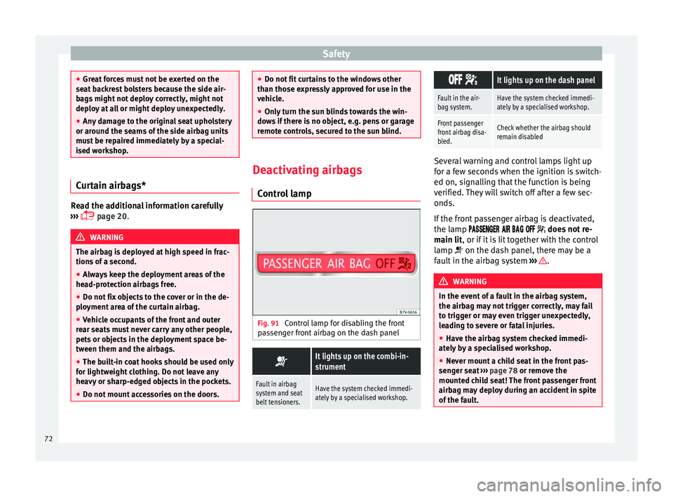
Contr o
l lamp Fig. 91
Control lamp for disabling the front
p a
s
senger front airbag on the dash panel ï´
It lights up on the combi-in-
strument
Fault in airbag
system and seat
belt tensioners.Have the system checked immedi-
ately by a specialised workshop. ïïï ï¹
It lights up on the dash panel
Fault in the air-
bag system.Have the system checked immedi-
ately by a specialised workshop.
Front passenger
front airbag disa-
bled.Check whether the airbag should
remain disabled
Several warning and control lamps light up
for a f
ew sec
onds when the ignition is switch-
ed on, signalling that the function is being
verified. They will switch off after a few sec-
onds.
If the front passenger airbag is deactivated,
the lamp ïïïïï
ïïï
ï ïïï ïïï ïïï ï¹ does not re-
main lit, or if it is lit together with the control
lamp ï´ on the dash panel, there may be a
fault in the airbag system âºâºâº .
WARNING
In the event of a fault in the airbag system,
the airbag m a
y not trigger correctly, may fail
to trigger or may even trigger unexpectedly,
leading to severe or fatal injuries.
â Have the airbag system checked immedi-
ately b
y a specialised workshop.
â Never mount a child seat in the front pas-
senger se
at âºâºâº page 78 or remove the
mounted child seat! The front passenger front
airbag may deploy during an accident in spite
of the fault. 72
Page 112 of 320
Operation
Opening and closing V ehic
l
e key set
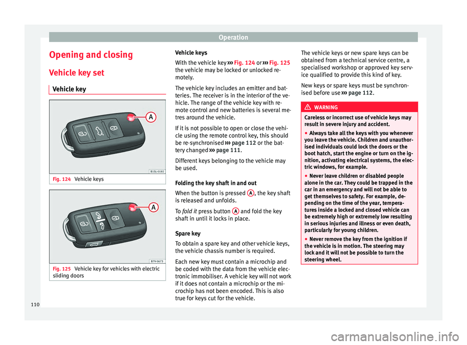
Vehicle key Fig. 124
Vehicle keys Fig. 125
Vehicle key for vehicles with electric
s lidin
g door
s Vehicle keys
W
ith the v
ehicle key âºâºâº Fig. 124 or âºâºâº Fig. 125
the vehicle may be locked or unlocked re-
motely.
The vehicle key includes an emitter and bat-
teries. The receiver is in the interior of the ve-
hicle. The range of the vehicle key with re-
mote control and new batteries is several me-
tres around the vehicle.
If it is not possible to open or close the vehi-
cle using the remote control key, this should
be re-synchronised âºâºâº page 112 or the bat-
tery changed âºâºâº page 111.
Different keys belonging to the vehicle may
be used.
Folding the key shaft in and out
When the button is pressed A , the key shaft
i s
r
eleased and unfolds.
To fold it press button A and fold the key
sh af
t
in until it locks in place.
Spare key
To obtain a spare key and other vehicle keys,
the vehicle chassis number is required.
Each new key must contain a microchip and
be coded with the data from the vehicle elec-
tronic immobiliser. A vehicle key will not work
if it does not contain a microchip or the mi-
crochip has not been encoded. This is also
true for keys cut for the vehicle. The vehicle keys or new spare keys can be
obtained fr
om a technical service centre, a
specialised workshop or approved key serv-
ice qualified to provide this kind of key.
New keys or spare keys must be synchron-
ised before use âºâºâº page 112. WARNING
Careless or incorrect use of vehicle keys may
re s
ult in severe injury and accident.
â Always take all the keys with you whenever
you le
ave the vehicle. Children and unauthor-
ised individuals could lock the doors or the
boot hatch, start the engine or turn on the ig-
nition, activating electrical systems, the elec-
tric windows, for example.
â Never leave children or disabled people
alone in the car
. They could be trapped in the
car in an emergency and will not be able to
get themselves to safety. For example, de-
pending on the time of the year, tempera-
tures inside a locked and closed vehicle can
be extremely high or extremely low resulting
in serious injuries and illness or even death,
particularly for young children.
â Never remove the key from the ignition if
the vehic
le is in motion. The steering may
lock and it will not be possible to turn the
steering wheel. 110
Page 113 of 320
Opening and closing
CAUTION
All of the vehicle keys contain electronic com-
ponents. Pr ot
ect them from damage, impacts
and humidity. Note
â Only u
se the key button when you require
the corresponding function. Pushing the but-
ton unnecessarily could accidentally unlock
the vehicle or trigger the alarm. It is also pos-
sible even when you are outside the radius of
action.
â Key operation can be greatly influenced by
overl
apping radio signals around the vehicle
working in the same range of frequencies
(e.g. radio transmitters, mobile telephones).
â Obstacles between the remote control and
the vehic
le, bad weather conditions and
draining batteries can considerably reduce
the range of the remote control. Control lamp on the vehicle key
Fig. 126
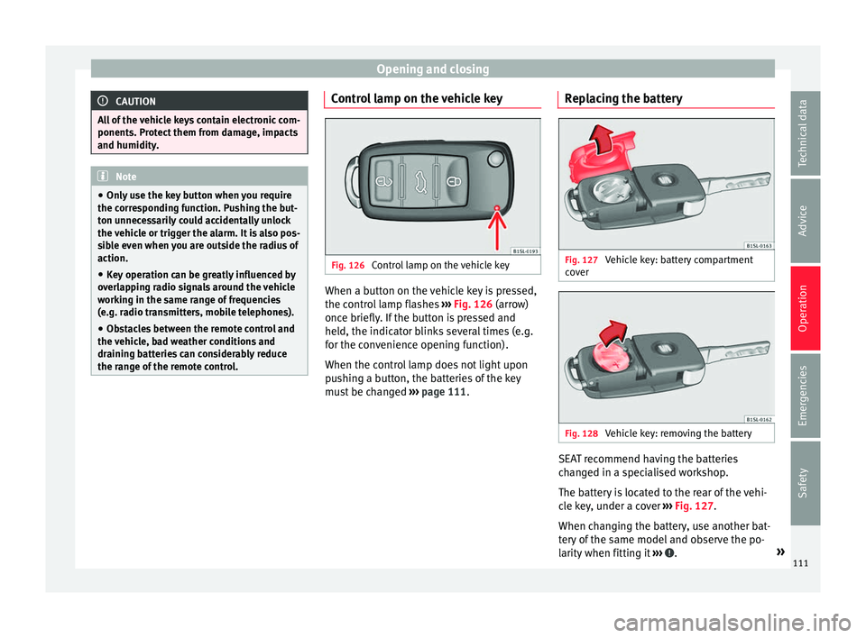
Control lamp on the vehicle key When a button on the vehicle key is pressed,
the c ontr
o
l lamp flashes âºâºâº Fig. 126 (arrow)
once briefly. If the button is pressed and
held, the indicator blinks several times (e.g.
for the convenience opening function).
When the control lamp does not light upon
pushing a button, the batteries of the key
must be changed âºâºâº page 111. Replacing the battery Fig. 127
Vehicle key: battery compartment
c o
v
er Fig. 128
Vehicle key: removing the battery SEAT recommend having the batteries
c
h
an
ged in a specialised workshop.
The battery is located to the rear of the vehi-
cle key, under a cover âºâºâº Fig. 127.
When changing the battery, use another bat-
tery of the same model and observe the po-
larity when fitting it âºâºâº .
»
111
Technical data
Advice
Operation
Emergencies
Safety
Page 120 of 320
Operation
key. On vehicles with the Keyless Access sys-
t em, the al
arm c
an also be disabled by grasp-
ing the door handle âºâºâº page 115. Note
â The al arm w
ill be triggered once more when
anybody enters the same zone of surveillance
or any other zone. If, for example, after open-
ing a door, the rear lid is also opened.
â The anti-theft alarm is not activated when
the vehic
le is locked from within using the
central locking button ï .
â If the driver door is unlocked mechanically
with the k ey
, only the driver door is unlocked,
the rest of the doors remain locked. Only
when the ignition has been turned on will the
other doors be available - but not unlocked -
and the central locking button will be activa-
ted.
â If the vehicle battery is run down or flat
then the anti-theft a
larm will not operate cor-
rectly. Vehicle interior monitoring system
and anti-t
o
w sy
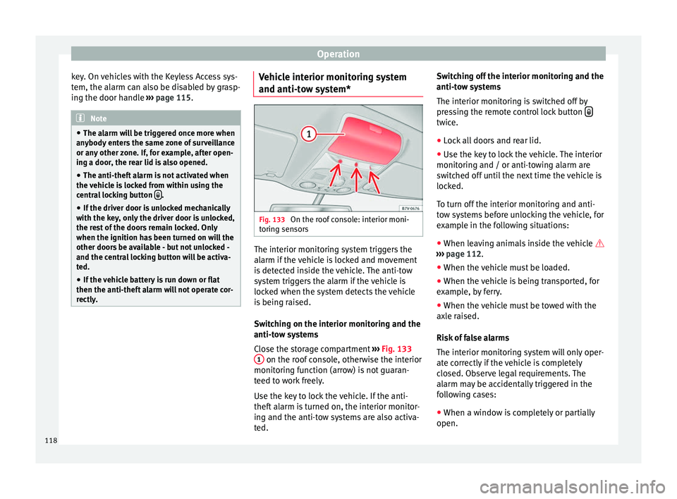
stem* Fig. 133
On the roof console: interior moni-
t orin
g sen
sors The interior monitoring system triggers the
al
arm if
the
vehicle is locked and movement
is detected inside the vehicle. The anti-tow
system triggers the alarm if the vehicle is
locked when the system detects the vehicle
is being raised.
Switching on the interior monitoring and the
anti-tow systems
Close the storage compartment âºâºâº Fig. 133
1 on the roof console, otherwise the interior
monit orin
g f
unction (arrow) is not guaran-
teed to work freely.
Use the key to lock the vehicle. If the anti-
theft alarm is turned on, the interior monitor-
ing and the anti-tow systems are also activa-
ted. Switching off the interior monitoring and the
anti-tow sy
stems
The interior monitoring is switched off by
pressing the remote control lock button ï twice.
â Lock all doors and rear lid.
â Use the key to lock the vehicle. The interior
monit orin
g and / or anti-t
owing alarm are
switched off until the next time the vehicle is
locked.
To turn off the interior monitoring and anti-
tow systems before unlocking the vehicle, for
example in the following situations:
â When leaving animals inside the vehicle ï
âºâºâº
page 112.
â When the vehicle must be loaded.
â When the vehicle is being transported, for
examp
le, by ferry.
â When the vehicle must be towed with the
axle r
aised.
Risk of false alarms
The interior monitoring system will only oper-
ate correctly if the vehicle is completely
closed. Observe legal requirements. The
alarm may be accidentally triggered in the
following cases:
â When a window is completely or partially
open.
118
Page 122 of 320
Operation
WARNING
Opening sliding doors while driving is dan-
ger ou
s. These doors may be pushed open or
closed when the vehicle accelerates or brakes
and cause serious injuries.
â Never open the sliding doors when the ve-
hicle i
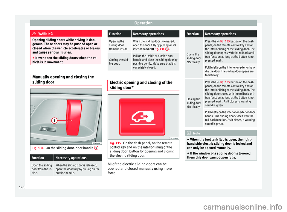
s in movement. Manually opening and closing the
slidin
g door Fig. 134
On the sliding door. door handle 1
FunctionNecessary operations
Open the sliding
door from the in-
side.When the sliding door is released,
open the door fully by pulling on the
outside handle.
FunctionNecessary operations
Opening the
sliding door
from the inside.When the sliding door is released,
open the door fully by pulling on its
interior handle
âºâºâº Fig. 134 1
.
Closing the slid-
ing door.Pull on the inside or outside door
handle and close the sliding door by
pushing gently. Make sure that it is
completely closed. Electric opening and closing of the
slidin
g door* Fig. 135
On the dash panel, on the remote
c ontr
o
l key and on the interior lining of the
sliding door: button for opening and closing
the electric sliding door. All of the electric sliding doors can be
opened and c
lo
sed m
anually using more
force.
FunctionNecessary operations
Opens the
sliding door
electrically.
Press the âºâºâº Fig. 135 button on the dash
panel, on the remote control key and on
the interior lining of the sliding door. The
sliding door opens with the rollback anti-
trap function as long as the button is not
pressed again.
Pull briefly on the interior or exterior han-
dle the door. The sliding door opens au-
tomatically.
Closing the
sliding door
electrically.
Press the âºâºâº Fig. 135 button on the dash
panel, on the remote control key and on
the interior lining of the sliding door. The
sliding door closes with the rollback anti-
trap function as long as the button is not
pressed again. As it closes, a warning
sound is given.
Pull briefly on the interior or exterior door
handle. The sliding door closes with the
roll-back function. As it closes, a warning
sound is given. Note
â When the fuel t
ank flap is open, the right-
hand side electric sliding door is locked and
can only be opened manually.
â If the window of a sliding door is lowered
them this door c
annot open fully.120
Page 180 of 320

Operation
WARNING
The auxiliary heater fumes contain carbon di-
ox ide, an odourl
ess and colourless toxic gas.
Carbon monoxide can cause people to lose
consciousness. It can also cause death.
â Never switch on the auxiliary heater or
leav
e it running in places that are enclosed or
unventilated.
â Never program the independent heating
syst
em to be activated and operated in
closed, unventilated areas. WARNING
The components of the auxiliary heater ex-
hau s
t system heat up a great deal. This could
cause a fire.
â Always park your vehicle so that no part of
the exhau
st system can come in contact with
flammable materials (such as dried grass). CAUTION
Never place food, medicines or other heat-
sens itiv
e objects close to the air vents. Food,
medicines and other heat-sensitive objects
may be damaged or made unsuitable for use
by the air coming from the air vents. Switching the auxiliary heater on and
off
Switching the auxiliary heater on:
ï
Manually using the instant on/off
button.âºâºâº
page
174
ONManually using the remote control.âºâºâº page
178
Automatically at the programmed
and enabled on time.âºâºâº page
179
Switching the auxiliary heater off: ï
Manually using the instant on/off
button for the air conditioner.âºâºâº
page
174
OFFManually using the remote control.âºâºâº page
178
Automatically after the programmed
time.âºâºâº page
179
Automatically when the light comes
on ï (fuel reserve).âºâºâº page
261
Automatically when the battery pow-
er drops to a very low level.âºâºâº page
280 Special feature
Af
t
er sw
itching the auxiliary heater off, it con-
tinues to run for a short period to completely
burn any fuel remaining in the auxiliary heat- er. The exhaust gases are also extracted from
the syst
em.
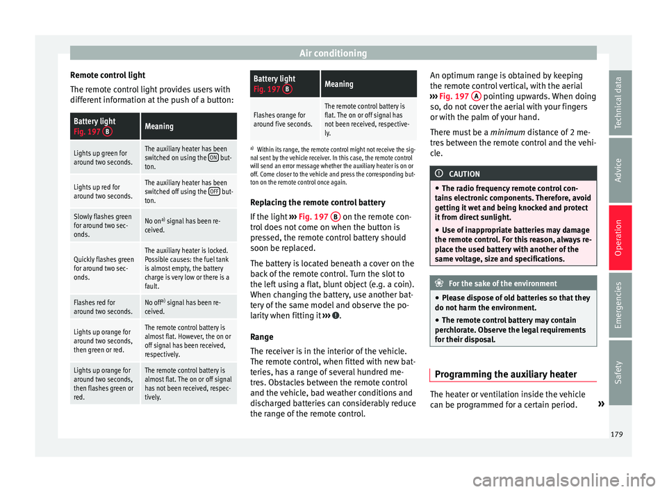
Remote control Fig. 197
Auxiliary heater: remote control
Fig. 197Meaning
ONSwitch the auxiliary heater on.
OFFSwitch the auxiliary heater off:
AAerial.
BLight. The auxiliary heater may accidentally switch
on if
a b
utt
on is pressed on the remote con-
trol by mistake. This may also occur outside
the range of the remote control or if the light
flashes.
178
Page 181 of 320
Air conditioning
Remote control light
The r emot
e c
ontrol light provides users with
different information at the push of a button:
Battery light
Fig. 197 BMeaning
Lights up green for
around two seconds.The auxiliary heater has been
switched on using the ON but-
ton.
Lights up red for
around two seconds.The auxiliary heater has been
switched off using the OFF but-
ton.
Slowly flashes green
for around two sec-
onds.No on a)
signal has been re-
ceived.
Quickly flashes green
for around two sec-
onds.The auxiliary heater is locked.
Possible causes: the fuel tank
is almost empty, the battery
charge is very low or there is a
fault.
Flashes red for
around two seconds.No off a)
signal has been re-
ceived.
Lights up orange for
around two seconds,
then green or red.The remote control battery is
almost flat. However, the on or
off signal has been received,
respectively.
Lights up orange for
around two seconds,
then flashes green or
red.The remote control battery is
almost flat. The on or off signal
has not been received, respec-
tively.
Battery light
Fig. 197 BMeaning
Flashes orange for
around five seconds.The remote control battery is
flat. The on or off signal has
not been received, respective-
ly.
a)
Within its range, the remote control might not receive the sig-
nal sent by the vehicle receiver. In this case, the remote control
will send an error message whether the auxiliary heater is on or
off. Come closer to the vehicle and press the corresponding but-
ton on the remote control once again.
Replacing the remote control battery
If the light âºâºâº
Fig. 197 B on the remote con-
tr o
l
does not come on when the button is
pressed, the remote control battery should
soon be replaced.
The battery is located beneath a cover on the
back of the remote control. Turn the slot to
the left using a flat, blunt object (e.g. a coin).
When changing the battery, use another bat-
tery of the same model and observe the po-
larity when fitting it âºâºâº .
R an
g
e
The receiver is in the interior of the vehicle.
The remote control, when fitted with new bat-
teries, has a range of several hundred me-
tres. Obstacles between the remote control
and the vehicle, bad weather conditions and
discharged batteries can considerably reduce
the range of the remote control. An optimum range is obtained by keeping
the remote c
ontrol vertical, with the aerial
âºâºâº Fig. 197 A pointing upwards. When doing
so , do not
c
over the aerial with your fingers
or with the palm of your hand.
There must be a minimum distance of 2 me-
tres between the remote control and the vehi-
cle. CAUTION
â The ra dio fr
equency remote control con-
tains electronic components. Therefore, avoid
getting it wet and being knocked and protect
it from direct sunlight.
â Use of inappropriate batteries may damage
the remote c
ontrol. For this reason, always re-
place the used battery with another of the
same voltage, size and specifications. For the sake of the environment
â Ple a
se dispose of old batteries so that they
do not harm the environment.
â The remote control battery may contain
perch
lorate. Observe the legal requirements
for their disposal. Programming the auxiliary heater
The heater or ventilation inside the vehicle
c
an be pr
ogr
ammed for a certain period. »
179
Technical data
Advice
Operation
Emergencies
Safety
Page 306 of 320
Index
tiredness detection . . . . . . . . . . . . . . . . . . . . . 229
ty r
e monit
oring indicator . . . . . . . . . . . . . . . . . 233
Assisted starting . . . . . . . . . . . . . . . . . . . . . . . . . . 51
Assist systems adaptive headlights . . . . . . . . . . . . . . . . . . . . . 130
auto Hold . . . . . . . . . . . . . . . . . . . . . . . . . . . . . 206
blind spot detector (BSD) with rear cross traf-fic alert (RTA) . . . . . . . . . . . . . . . . . . . . . . . . . 222
brake assist system (BAS) . . . . . . . . . . . . . . . . 204
cruise control system . . . . . . . . . . . . . . . . . . . . 219
dynamic chassis control (DCC) . . . . . . . . . . . . 230
lane Assist . . . . . . . . . . . . . . . . . . . . . . . . . . . . . 220
lane assist system . . . . . . . . . . . . . . . . . . . . . . 220
optical parking system . . . . . . . . . . . . . . . . . . . 210
park Assist . . . . . . . . . . . . . . . . . . . . . . . . . . . . 211
park assist system . . . . . . . . . . . . . . . . . . . . . . 211
parking assistance . . . . . . . . . . . . . . . . . . . . . . 209
parking distance warning system . . . . . . . . . . 209
rear assist . . . . . . . . . . . . . . . . . . . . . . . . . . . . . 215
rear cross traffic alert (RTA) . . . . . . . . . . . . . . . 222
rear View Camera . . . . . . . . . . . . . . . . . . . . . . . 215
sign Assist . . . . . . . . . . . . . . . . . . . . . . . . . . . . . 227
Start-Stop . . . . . . . . . . . . . . . . . . . . . . . . . . . . . 207
start assistance . . . . . . . . . . . . . . . . . . . . . . . . 206
traction control when accelerating (ASR) . . .204, 205
traffic signal detection . . . . . . . . . . . . . . . . . . . 227
Auto Hold . . . . . . . . . . . . . . . . . . . . . . . . . . . . . . . 206
Automatic belt retractor . . . . . . . . . . . . . . . . . . . . . 67
Automatic car wash switching Auto Hold off . . . . . . . . . . . . . . . . . . 207
switching the start assist off . . . . . . . . . . . . . . 207
Automatic dipped beam control . . . . . . . . . . . . . 130
Automatic gearbox . . . . . . . . . . . . . . . . . . . . . . . . 193 driving tips . . . . . . . . . . . . . . . . . . . . . . . . . . . . 195
emergency release . . . . . . . . . . . . . . . . . . . . . . . 35
ignition key removal lock . . . . . . . . . . . . . . . . . 184
kick-down . . . . . . . . . . . . . . . . . . . . . . . . . . . . . 195
malfunction . . . . . . . . . . . . . . . . . . . . . . . . . . . . 196 AUX-IN . . . . . . . . . . . . . . . . . . . . . . . . . . . . . . . . . . 108
Auxili
ary heater . . . . . . . . . . . . . . . . . . . . . . . . . . 177
automatic off . . . . . . . . . . . . . . . . . . . . . . . . . . . 263
operating instructions . . . . . . . . . . . . . . . . . . . 180
programming . . . . . . . . . . . . . . . . . . . . . . . . . . 179
remote control . . . . . . . . . . . . . . . . . . . . . . . . . 178
remote control range . . . . . . . . . . . . . . . . . . . . 179
remote control: replacing the battery . . . . . . . 179
special features . . . . . . . . . . . . . . . . . . . . . . . . 178
switching off . . . . . . . . . . . . . . . . . . . . . . . . . . . 178
switching on . . . . . . . . . . . . . . . . . . . . . . . . . . . 178
things to note . . . . . . . . . . . . . . . . . . . . . . . . . . 180
Auxiliary heater remote control auxiliary heater . . . . . . . . . . . . . . . . . . . . . . . . . 178
replacing the battery . . . . . . . . . . . . . . . . . . . . 179
B BAS see Brake assist systems . . . . . . . . . . . . . . . . . 204
Battery changing in the vehicle key . . . . . . . . . . . . . . . 111
Before setting off . . . . . . . . . . . . . . . . . . . . . . . . . . 56
Belt height adjustment . . . . . . . . . . . . . . . . . . . . . 67
Belt tension device service and disposal . . . . . . . . . . . . . . . . . . . . . 68
Belt tensioner . . . . . . . . . . . . . . . . . . . . . . . . . . . . . 67
Belt tension limiter . . . . . . . . . . . . . . . . . . . . . . . . . 67
Belt tightening . . . . . . . . . . . . . . . . . . . . . . . . . . . . 67
Bicycle carrier fitting on the tow hitch ball . . . . . . . . . . . . . . . 237
maximum load . . . . . . . . . . . . . . . . . . . . . . . . . 237
Biodiesel . . . . . . . . . . . . . . . . . . . . . . . . . . . . . . . . 265
Blind spot detector (BSD) . . . . . . . . . . . . . . . . . . 222 control lamps . . . . . . . . . . . . . . . . . . . . . . . . . . 222
driving situations . . . . . . . . . . . . . . . . . . . . . . . 225
indication in the external rear view mirror . . . 223
malfunction . . . . . . . . . . . . . . . . . . . . . . . . . . . . 222 operating . . . . . . . . . . . . . . . . . . . . . . . . . . . . . . 223
tow
ing . . . . . . . . . . . . . . . . . . . . . . . . . . . . . . . . 227
Bonnet . . . . . . . . . . . . . . . . . . . . . . . . . . . . . . . . . . 11 opening and closing . . . . . . . . . . . . . . . . . . . . 270
Boot hatch emergency locking and unlocking . . . . . . . . . . . 10
Bottle holders . . . . . . . . . . . . . . . . . . . . . . . . . . . . 168
Brake brake servo . . . . . . . . . . . . . . . . . . . . . . . . . . . . 191
emergency braking function . . . . . . . . . . . . . . 189
Brake assist system . . . . . . . . . . . . . . . . . . . . . . . 203
Brake assist systems . . . . . . . . . . . . . . . . . . . . . . 203
Brake fluid . . . . . . . . . . . . . . . . . . . . . . . . . . . . . . . 41 specification . . . . . . . . . . . . . . . . . . . . . . . . . . . 278
Brakes . . . . . . . . . . . . . . . . . . . . . . . . . . . . . . . . . . 187 brake assist systems . . . . . . . . . . . . . . . . . . . . 203
brake fluid . . . . . . . . . . . . . . . . . . . . . . . . . . . . . 278
brake fluid level . . . . . . . . . . . . . . . . . . . . . . . . 279
brake pads . . . . . . . . . . . . . . . . . . . . . . . . . . . . 190
changing the brake fluid . . . . . . . . . . . . . . . . . 279
control and warning lamps . . . . . . . . . . . . . . . 187
electronic parking brake . . . . . . . . . . . . . . . . . 189
running in new brake pads . . . . . . . . . . . . . . . 190
Brake servo . . . . . . . . . . . . . . . . . . . . . . . . . 191, 203
Brake system fault . . . . . . . . . . . . . . . . . . . . . . . . . . . . . . . . . . 191
Brake systems . . . . . . . . . . . . . . . . . . . . . . . . . . . 203
Braking brake assist system . . . . . . . . . . . . . . . . . . . . . 203
BSD see Blind spot detector . . . . . . . . . . . . . . . . . . 222
Bulb malfunction see Changing bulbs . . . . . . . . . . . . . . . . . . . . . . 91
C
Capacities . . . . . . . . . . . . . . . . . . . . . . . . . . . . . . . . 39 windshield wiper fluid tank . . . . . . . . . . . . . . . 280
304