run flat Seat Alhambra 2017 Owner's Manual
[x] Cancel search | Manufacturer: SEAT, Model Year: 2017, Model line: Alhambra, Model: Seat Alhambra 2017Pages: 320, PDF Size: 6.88 MB
Page 46 of 320
The essentials
Action in the event of a punc-
t ur
e
Wh
at to do first ●
Park the vehicle on a horizontal surface
and in a saf e p
lace as far away from traffic as
possible.
● Apply the handbrake.
● Switch on the hazard warning lights.
● Manual gearbox: select the 1s
t gear.
● Automatic gearbox: Move the sel
ector lever
to position P.
● If you are towing a trailer, unhitch it from
your v
ehicle.
● Keep the vehicle tool kit ready*
›››
page 82.
● Observe the applicable legislation for each
countr
y (reflective vest, warning triangles,
etc.).
● All occupants should leave the vehicle and
wait in a s
afe place (for instance behind the
roadside crash barrier). WARNING
● Alw a
ys observe the above steps and pro-
tect yourself and other road users.
● If you change the wheel on a slope, block
the wheel on the oppo
site side of the car with
a stone or similar to prevent the vehicle from
moving. Repairing a tyre with the anti-punc-
t
ur
e k
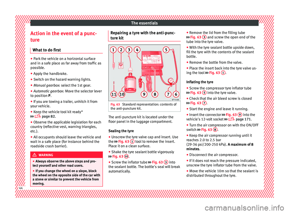
it Fig. 63
Standard representation: contents of
the anti-p u
nct
ure kit. The anti-puncture kit is located under the
floor p
anel
in the lug
gage compartment.
Sealing the tyre
● Unscrew the tyre valve cap and insert. Use
the ›››
Fig. 63 1 tool to remove the insert.
Pl ac
e it
on a clean surface.
● Shake the tyre sealant bottle vigorously
›››
Fig. 63 10 .
● Screw the inflator tube ››
›
Fig. 63 3 into
the se al
ant
bottle. The bottle's seal will break
automatically. ●
Remov
e the lid from the filling tube
››› Fig. 63 3 and screw the open end of the
t ube int
o the ty
re valve.
● With the tyre sealant bottle upside down,
fill
the tyre with the contents of the sealant
bottle.
● Remove the bottle from the valve.
● Place the insert back into the tyre valve us-
ing the too
l ››› Fig. 63 1 .
Infl atin
g the ty
re
● Screw the compressor tyre inflator tube
›››
Fig. 63 5 into the tyre valve.
● Check that the air bleed screw is closed
› ›
›
Fig. 63 7 .
● Start the engine and leave it running.
● Insert the connector ››
›
Fig. 63 9 into the
v ehic
l
e's 12-volt socket ›››
page 171.
● Turn the air compressor on with the ON/OFF
switc
h ››› Fig. 63 8 .
● Keep the air compressor running until it
r e
ac
hes 2.0 to 2.5 bar
(29-36 psi/200-250 kPa). A maximum of 8
minutes.
● Disconnect the air compressor.
● If it does not reach the pressure indicated,
uns
crew the tyre inflator tube from the valve.
● Move the vehicle 10m so that the sealant is
dis trib
uted throughout the tyre.44
Page 50 of 320
The essentials
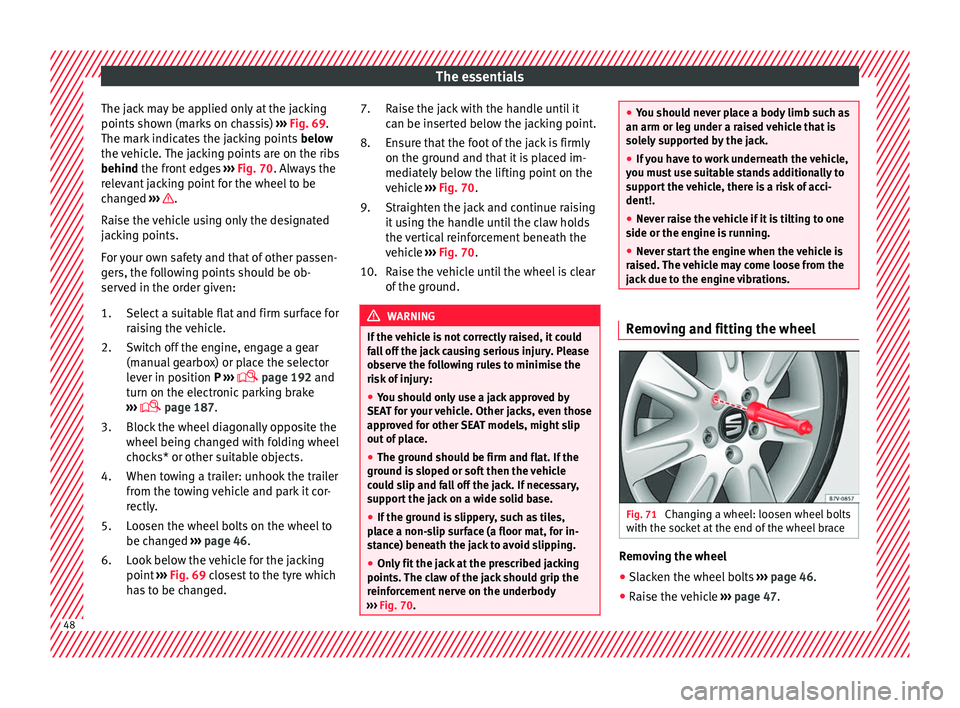
The jack may be applied only at the jacking
points sho
wn (m
arks on chassis) ››› Fig. 69.
The mark indicates the jacking points below
the vehicle. The jacking points are on the ribs
behind the front edges ››› Fig. 70. Always the
relevant jacking point for the wheel to be
changed ››› .
R ai
se the
vehicle using only the designated
jacking points.
For your own safety and that of other passen-
gers, the following points should be ob-
served in the order given:
Select a suitable flat and firm surface for
raising the vehicle.
Switch off the engine, engage a gear
(manual gearbox) or place the selector
lever in position P ›››
page 192 and
turn on the electronic parking brake
››› page 187.
Block the wheel diagonally opposite the
wheel being changed with folding wheel
chocks* or other suitable objects.
When towing a trailer: unhook the trailer
from the towing vehicle and park it cor-
rectly.
Loosen the wheel bolts on the wheel to
be changed ››› page 46.
Look below the vehicle for the jacking
point ››› Fig. 69 closest to the tyre which
has to be changed.
1.
2.
3.
4.
5.
6. Raise the jack with the handle until it
can be inser
ted below the jacking point.
Ensure that the foot of the jack is firmly
on the ground and that it is placed im-
mediately below the lifting point on the
vehicle ››› Fig. 70.
Straighten the jack and continue raising
it using the handle until the claw holds
the vertical reinforcement beneath the
vehicle ››› Fig. 70.
Raise the vehicle until the wheel is clear
of the ground. WARNING
If the vehicle is not correctly raised, it could
fa l
l off the jack causing serious injury. Please
observe the following rules to minimise the
risk of injury:
● You should only use a jack approved by
SEAT f
or your vehicle. Other jacks, even those
approved for other SEAT models, might slip
out of place.
● The ground should be firm and flat. If the
ground i
s sloped or soft then the vehicle
could slip and fall off the jack. If necessary,
support the jack on a wide solid base.
● If the ground is slippery, such as tiles,
plac
e a non-slip surface (a floor mat, for in-
stance) beneath the jack to avoid slipping.
● Only fit the jack at the prescribed jacking
points. The c
law of the jack should grip the
reinforcement nerve on the underbody
››› Fig. 70. 7.
8.
9.
10.
●
You shou l
d never place a body limb such as
an arm or leg under a raised vehicle that is
solely supported by the jack.
● If you have to work underneath the vehicle,
you mus
t use suitable stands additionally to
support the vehicle, there is a risk of acci-
dent!.
● Never raise the vehicle if it is tilting to one
side or the engine i
s running.
● Never start the engine when the vehicle is
raised.
The vehicle may come loose from the
jack due to the engine vibrations. Removing and fitting the wheel
Fig. 71
Changing a wheel: loosen wheel bolts
w ith the soc
k
et at the end of the wheel brace Removing the wheel
● Slacken the wheel bolts ››
›
page 46.
● Raise the vehicle ›››
page 47. 48
Page 55 of 320
The essentials
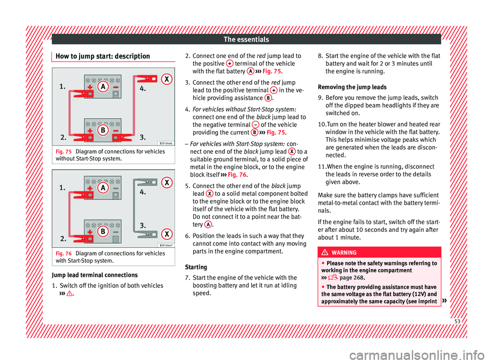
How to jump start: description Fig. 75
Diagram of connections for vehicles
w ithout
Start-Stop system. Fig. 76
Diagram of connections for vehicles
w ith
St
art-Stop system. Jump lead terminal connections
1. Switch off the ignition of both vehicles
››
›
. 2. Connect one end of the
re
d
jump lead to
the positive + terminal of the vehicle
w ith the fl
at
battery A
› ››
Fig. 75
.
3.
Connect the other end of the red
jump
lead to the positive terminal + in the ve-
hic l
e pr
oviding assistance B .
4. For vehicles without Start-Stop system:
connect
one end of
the black jump lead to
the negative terminal – of the vehicle
pr o
v
iding the current B
› ››
Fig. 75
.
– F
or vehicles with Start-Stop system: con-
nect one end of
the black jump lead X to a
s uit
ab
le ground terminal, to a solid piece of
metal in the engine block, or to the engine
block itself ››› Fig. 76.
5. Connect the other end of the black
jump
lead X to a solid metal component bolted
t o the en
gine b
lock or to the engine block
itself of the vehicle with the flat battery.
Do not connect it to a point near the bat-
tery A .
6. Position the leads in such a way that they cannot
c
ome into contact with any moving
parts in the engine compartment.
Starting
7. Start the engine of the vehicle with the boostin
g battery and let it run at idling
speed. 8. Start the engine of the vehicle with the flat
batter
y and wait for 2 or 3 minutes until
the engine is running.
Removing the jump leads
9. Before you remove the jump leads, switch off the dipped be
am headlights if they are
switched on.
10.Turn on the heater blower and heated rear window in the
vehicle with the flat battery.
This helps minimise voltage peaks which
are generated when the leads are discon-
nected.
11.When the engine is running, disconnect the lea
ds in reverse order to the details
given above.
Make sure the battery clamps have sufficient
metal-to-metal contact with the battery termi-
nals.
If the engine fails to start, switch off the start-
er after about 10 seconds and try again after
about 1 minute. WARNING
● Ple a
se note the safety warnings referring to
working in the engine compartment
››› page 268.
● The battery providing assistance must have
the same v
oltage as the flat battery (12V) and
approximately the same capacity (see imprint » 53
Page 120 of 320
Operation
key. On vehicles with the Keyless Access sys-
t em, the al
arm c
an also be disabled by grasp-
ing the door handle ››› page 115. Note
● The al arm w
ill be triggered once more when
anybody enters the same zone of surveillance
or any other zone. If, for example, after open-
ing a door, the rear lid is also opened.
● The anti-theft alarm is not activated when
the vehic
le is locked from within using the
central locking button .
● If the driver door is unlocked mechanically
with the k ey
, only the driver door is unlocked,
the rest of the doors remain locked. Only
when the ignition has been turned on will the
other doors be available - but not unlocked -
and the central locking button will be activa-
ted.
● If the vehicle battery is run down or flat
then the anti-theft a
larm will not operate cor-
rectly. Vehicle interior monitoring system
and anti-t
o
w sy
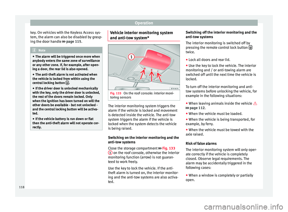
stem* Fig. 133
On the roof console: interior moni-
t orin
g sen
sors The interior monitoring system triggers the
al
arm if
the
vehicle is locked and movement
is detected inside the vehicle. The anti-tow
system triggers the alarm if the vehicle is
locked when the system detects the vehicle
is being raised.
Switching on the interior monitoring and the
anti-tow systems
Close the storage compartment ››› Fig. 133
1 on the roof console, otherwise the interior
monit orin
g f
unction (arrow) is not guaran-
teed to work freely.
Use the key to lock the vehicle. If the anti-
theft alarm is turned on, the interior monitor-
ing and the anti-tow systems are also activa-
ted. Switching off the interior monitoring and the
anti-tow sy
stems
The interior monitoring is switched off by
pressing the remote control lock button twice.
● Lock all doors and rear lid.
● Use the key to lock the vehicle. The interior
monit orin
g and / or anti-t
owing alarm are
switched off until the next time the vehicle is
locked.
To turn off the interior monitoring and anti-
tow systems before unlocking the vehicle, for
example in the following situations:
● When leaving animals inside the vehicle
›››
page 112.
● When the vehicle must be loaded.
● When the vehicle is being transported, for
examp
le, by ferry.
● When the vehicle must be towed with the
axle r
aised.
Risk of false alarms
The interior monitoring system will only oper-
ate correctly if the vehicle is completely
closed. Observe legal requirements. The
alarm may be accidentally triggered in the
following cases:
● When a window is completely or partially
open.
118
Page 183 of 320
Driving
If the battery charge is low, the auxiliary heat-
er w i
l
l switch off automatically or will not
even switch on. This avoids problems when
starting the engine.
● The heater will switch on just once each
time. The timer wi
ll also have to be switched
back on every time it is required. Note
● Noise w i
ll be heard while the auxiliary
heater is running.
● When the air humidity is high and the out-
side temper
ature low, the heating system
may evaporate condensation from the auxili-
ary heater. In this case, steam may be re-
leased from underneath the vehicle. This is
completely normal and there is no need to
suspect a fault!
● If the auxiliary heater runs several times
over a pr
olonged period, the vehicle battery
may run flat. To re-charge the battery, drive
the vehicle for a long distance. As a general
rule, drive for as much time as the auxiliary
heating was working. Driving
Ad dr
e
ss
Introduction The power steering is not hydraulic but elec-
tromec
h
anical. The advantage of this steer-
ing system is that it disposes of hydraulic
tubes, hydraulic oil, the pump, filter and oth-
er components. The electromechanical sys-
tem saves fuel. While a hydraulic system re-
quires oil pressure to be maintained, electro-
mechanical steering only requires energy
when the steering wheel is turned.
With the power steering system, the assisted
steering function automatically adjusts ac-
cording to the vehicle speed, the steering tor-
que and the wheel turning angle. The power
steering only works when the engine is run-
ning. WARNING
If the power steering is not working then the
st eerin
g wheel is much more difficult to turn
and the vehicle more difficult to control.
● The power steering only works when the
engine is
running.
● Never allow the vehicle to move when the
engine is
switched off.
● Never remove the key from the ignition if
the vehic
le is in motion. The steering may lock and it will not be possible to turn the
st
eerin
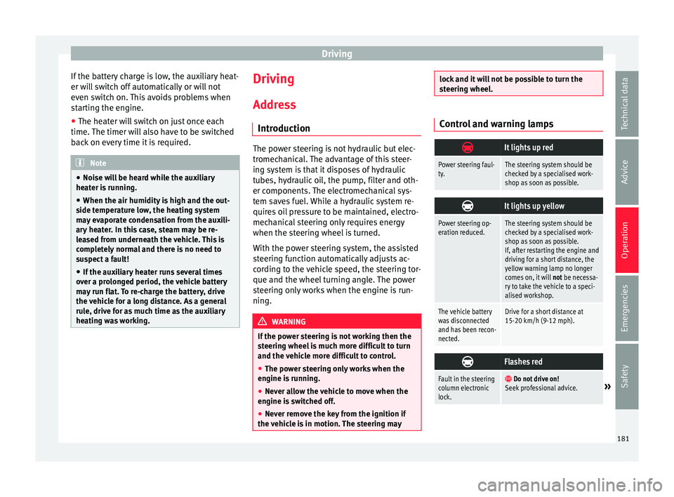
g wheel. Control and warning lamps
It lights up red
Power steering faul-
ty.The steering system should be
checked by a specialised work-
shop as soon as possible.
It lights up yellow
Power steering op-
eration reduced.The steering system should be
checked by a specialised work-
shop as soon as possible.
If, after restarting the engine and
driving for a short distance, the
yellow warning lamp no longer
comes on, it will
not be necessa-
ry to take the vehicle to a speci-
alised workshop.
The vehicle battery
was disconnected
and has been recon-
nected.Drive for a short distance at
15-20 km/h (9-12 mph).
Flashes red
Fault in the steering
column electronic
lock.
Do not drive on!
Seek professional advice.» 181
Technical data
Advice
Operation
Emergencies
Safety
Page 186 of 320
Operation
be operated which may result in serious in-
jury
.
● Nev
er leave children or disabled people
alone in the car
. Passengers could be trapped
in the car in an emergency and not be able to
get themselves to safety. For example, de-
pending on the time of the year, tempera-
tures inside a locked and closed vehicle can
be extremely high or extremely low resulting
in serious injuries and illness or even death,
particularly for young children.
● Never remove the key from the ignition if
the vehic
le is in motion. The steering may
lock and it will not be possible to turn the
steering wheel. Note
● If the k ey
is left in the ignition lock with the
engine off for long periods, the vehicle bat-
tery will run flat.
● For automatic gearbox vehicles, the key can
only be r
emoved from the ignition lock if the
gear selector lever is in position P. In this
case, press and release the selector lever
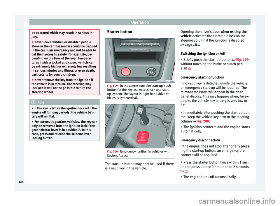
locking button. Starter button
Fig. 199
In the centre console: start-up push
b utt
on f
or the Keyless Access lock and start-
up system. The layout in right-hand drive ve-
hicles is symmetrical. Fig. 200
Emergency ignition in vehicles with
K eyl
e
ss Access. The start-up button may only be used if there
i
s a
valid key in the vehicle. Opening the driver's door
when exitin
g the
vehicle activates the electronic lock on the
steering column if the ignition is disabled
››› page 181.
Switching the ignition on/off
● Briefly push the start-up button ›››
Fig. 199
without touching the brake or clutch ped-
al ››› .
Emer g
ency
starting function
If no valid key is detected inside the vehicle,
an emergency start-up will be required. The
relevant message will appear in the dash
panel display. This may happen when, for ex-
ample, the vehicle key battery is very low or
flat:
● Immediately after pushing the start-up but-
ton, keep the
vehicle key next to the steering
column ››› Fig. 200.
● The ignition connects and the engine starts
automatic
ally.
Emergency disconnection
If the engine does not stop after briefly press-
ing the start-up button, an emergency dis-
connect will be required:
● Press the starter button twice within 1 sec-
ond or pres
s it once for more than 2 seconds
››› .
● The engine turns off automatically.
184
Page 188 of 320
Operation
●
Do not p u
sh or tow start the engine. Un-
burnt fuel could damage the catalytic con-
verter. For the sake of the environment
Do not warm the engine at idle speed; start
driv ing immedi
ately if the visibility is OK.
This helps the engine reach operating tem-
perature faster and reduces emissions. Note
● For e x
ample, if the key battery is very worn
or flat, the engine cannot be started with the
starter button. In this case, remove the igni-
tion button from the lock and insert the key.
● Electrical devices with a high power con-
sumption are sw
itched off temporarily when
the engine starts.
● When the engine is started cold, there may
be stron
g vibrations for a few moments for
technical reasons. This is quite normal, and
no cause for concern.
● At temperatures below +5°C (+41°F),
smoke ma
y be given off below the vehicle
when the additional heater is connected. Stopping the engine
Complete operations only in the sequence
giv
en:
Vehicles without
Keyless AccessVehicles with
Keyless Access
1.Bring the vehicle to a full stop ››› .
2.Press and hold the brake pedal until the step 4 is
performed.
3.If the vehicle has an automatic gearbox, place theselector lever in position P.
4.Connect the electronic parking brake ››› page 187.
5.Turn the vehicle key in
the ignition lock to po-
sition ››› Fig. 198 1
.
Briefly press the start-
up button
››› Fig. 199. If
the engine fails to
switch off, perform an
emergency disconnect
››› page 184.
6.If the vehicle is equipped with a manual gearbox,
put it into 1st or reverse. WARNING
Never switch off the engine while the vehicle
is mo
ving. You may lose control of the vehicle
and there is a risk of serious accident.
● The airbags and belt tensioners do not
work when the ignition i
s switched off.
● The brake servo does not work with the en-
gine off. T
o stop, the brake pedal must be
pressed with more force.
● As the power steering does not work if the
engine is
not running, you will need more
strength to steer than normally. ●
If the k ey
is removed from the ignition, the
steering may lock and it will not be possible
to steer the vehicle. CAUTION
● If the v
ehicle is stopped and the Start-Stop
system* switches off the engine, the ignition
remains switched on. Make sure that the igni-
tion is switched off before leaving the vehi-
cle, otherwise the battery could discharge.
● If the engine has been driven at high speed
for a pro
longed period of time, it may over-
heat when turned off. To avoid engine dam-
age, allow the engine to run for approximate-
ly two minutes in neutral before switching it
off. Note
● In v ehic
les with automatic gearbox, the key
can only be removed when the selector lever
is in position P.
● After stopping the engine, the engine com-
partment
fan may continue running for a few
minutes, even when the ignition has been
switched off or the key removed. The radiator
fan is automatically switched off. Electronic immobiliser
The gear lock prevents the engine from being
s
t
ar
ted with an unauthorised key and the ve-
hicle being moved.
186
Page 192 of 320
Operation
because braking is only applied to the rear
wheels. A
lw
ays use the foot brake.
● Never accelerate from the engine compart-
ment with the en
gine running and a gear or a
gear range engaged. The vehicle could move,
even if the parking brake is applied. Note
● In vehic
les with a manual gearbox: when
the clutch pedal is released and the accelera-
tor pressed at the same time, the electronic
parking brake is automatically released.
● If the vehicle battery is flat, it will not be
poss
ible to disconnect the electronic parking
brake. Use the jump-start ›››
page 51.
● When the electronic parking brake is ap-
plied or rel
eased, noises may be heard.
● If the electronic parking brake has not been
used for a lon
g while, the system sometimes
performs automatic and audible checks while
the vehicle is at a standstill. Parking
When parking your vehicle, all legal require-
ments
shou
l
d be observed.
To park the vehicle
Complete operations only in the sequence
given. ● Park the vehicle on a suitable surface ›››
.●
Pr e
s
s and hold the brake pedal until the ve-
hicle comes to a standstill.
● Connect the electronic parking brake
›››
page 189.
● For an automatic gearbox, move the selec-
tor lev
er to position P.
● Switch off the engine and release the brake
pedal.
● R
emove the key from the ignition.
● If necessary, turn the steering wheel slight-
ly to loc
k the steering.
● With a manual gearbox, engage 1st gear on
flat gr
ound and slopes, or even reverse gear
on hills, and release the clutch pedal.
● Ensure that all passengers leave the vehi-
cle, e
specially children.
● When leaving the vehicle, take all keys with
you.
● Loc
k the vehicle.
Additiona
l information for steep ascents and
descents
Before switching off the engine, rotate the
steering wheel so that if the vehicle should
move, it will be held by the kerb.
● On slopes, turn the front wheels so that
they are ag
ainst the edge of the kerb.
● Uphill, turn the wheels towards the centre
of the r o
ad. WARNING
The components of the exhaust system reach
ver y
high temperatures. This could cause a
fire and considerable damage.
● Always park your vehicle so that no part of
the exhau
st system can come in contact with
flammable materials (such as wood,
leaves,dried grass, or spilled fuel). CAUTION
● Spec i
al care should be taken when parking
in areas with high kerbs or fixed barriers. Ob-
jects protruding from the ground may dam-
age the bumper or other parts of the vehicle
during manoeuvres. To avoid damage, stop
before the wheels touch the barrier or kerb.
● Special attention is required when driving
through entranc
es, over ramps, kerbs or oth-
er objects. The vehicle underbody, bumpers,
mudguards and running gear, and the engine
and exhaust system could be damaged as
you drive over these objects. Information on the brakes
For the first 200 to 300 km (100 to 200
mi
l
e
s), new brake pads have not yet reached
their maximum braking capacity, and need to
be “run in” first ››› . The slightly reduced
br ak in
g effect can be compensated for by in-
creasing pressure on the brake pedal. While
running in, the full braking distance or
190
Page 208 of 320
Operation
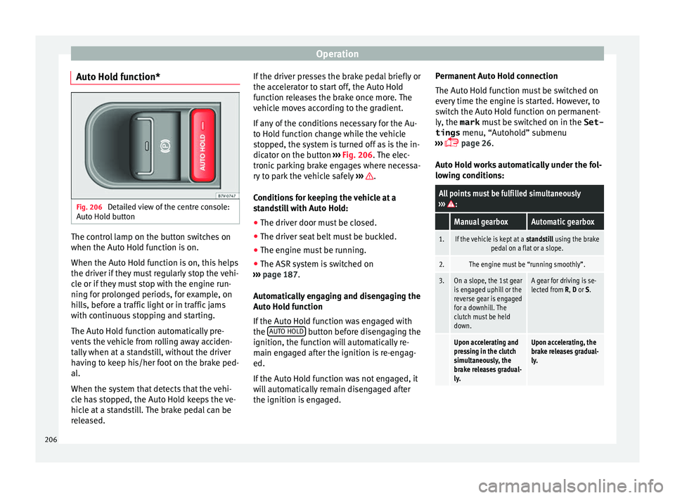
Auto Hold function* Fig. 206
Detailed view of the centre console:
Aut o Ho
l
d button The control lamp on the button switches on
when the Aut
o Ho
l
d function is on.
When the Auto Hold function is on, this helps
the driver if they must regularly stop the vehi-
cle or if they must stop with the engine run-
ning for prolonged periods, for example, on
hills, before a traffic light or in traffic jams
with continuous stopping and starting.
The Auto Hold function automatically pre-
vents the vehicle from rolling away acciden-
tally when at a standstill, without the driver
having to keep his/her foot on the brake ped-
al.
When the system that detects that the vehi-
cle has stopped, the Auto Hold keeps the ve-
hicle at a standstill. The brake pedal can be
released. If the driver presses the brake pedal briefly or
the accel
erator to start off, the Auto Hold
function releases the brake once more. The
vehicle moves according to the gradient.
If any of the conditions necessary for the Au-
to Hold function change while the vehicle
stopped, the system is turned off as is the in-
dicator on the button ››› Fig. 206. The elec-
tronic parking brake engages where necessa-
ry to park the vehicle safely ››› .
C ondition
s
for keeping the vehicle at a
standstill with Auto Hold:
● The driver door must be closed.
● The driver seat belt must be buckled.
● The engine must be running.
● The ASR system is switched on
›››
page 187.
Automatically engaging and disengaging the
Auto Hold function
If the Auto Hold function was engaged with
the AUTO HOLD button before disengaging the
ignition, the f u
nction w
ill automatically re-
main engaged after the ignition is re-engag-
ed.
If the Auto Hold function was not engaged, it
will automatically remain disengaged after
the ignition is engaged. Permanent Auto Hold connection
The Auto Hol
d function must be switched on
every time the engine is started. However, to
switch the Auto Hold function on permanent-
ly, the mark must be switched on in the Set-
tings menu, “Autohold” submenu
››› page 26.
Auto Hold works automatically under the fol-
lowing conditions:
All points must be fulfilled simultaneously
››› :
Manual gearboxAutomatic gearbox
1.If the vehicle is kept at a standstill using the brake
pedal on a flat or a slope.
2.The engine must be “running smoothly”.
3.On a slope, the 1st gear
is engaged uphill or the
reverse gear is engaged
for a downhill. The
clutch must be held
down.A gear for driving is se-
lected from R, D or S.
Upon accelerating and
pressing in the clutch
simultaneously, the
brake releases gradual-
ly.Upon accelerating, the
brake releases gradual-
ly. 206
Page 219 of 320
Driver assistance systemsOperations in vehicles with the optical parking
system (OPS)
Switching the dis-
play on automati-
cally:Select reverse gear with the igni-
tion switched on or the engine run-
ning. Mode 1 will be displayed.
Switching the dis-
play off manually:
Press a button to select the area on
the radio or the navigation system
››› Booklet Radio or ››› Booklet Navi-
gation system.
OR: press the
button on the
screen.
OR: after switching off the ignition,
the rear assist image remains on
the screen for a short period.
Press button .
Switching off the
display by disen-
gaging reverse
gear:The OPS display will immediately
be shown.
Switching off the
display by driving
forwards:Drive forwards at more than ap-
prox. 10 km/h (6 mph). Things to note
1) Do not use the rear assist system in the fol-
lowing cases:
– If there is a fault in the dynamic chassis control (DCC).
– If the image displayed is not very clear or reliable (low
visibility or dirty lens).
– If the space behind the vehicle cannot be clearly or
completely recognised.
1) Do not use the rear assist system in the fol-
lowing cases:
– If the vehicle has been overloaded at the rear.
– If the driver is not familiar with the system.
– If the rear lid is open.
– If the position and installation angle of the camera
have been changed, e.g. in a rear-end collision. Have a
specialised workshop check the system.
2) Optical illusions of the camera (examples)
The rear assist camera produces two-dimensional im-
ages. Any cracks in or objects protruding from the
ground or from other vehicles are more difficult to spot
or cannot be seen due to a lack of depth in the image
displayed.
Objects or other vehicles may seem to be closer or fur-
ther away than what they really are:
– On changing from a flat surface to a slope or gradient.
– On changing from a slope or gradient to a flat surface.
– If the vehicle has been overloaded at the rear.
– On approaching protruding objects. These objects
may be outside the angle of vision of the camera when
reversing.
Cleaning the camera lens
K
eep the c
amer
a lens clean and clear of snow
and ice:
● Moisten the lens using a commercially
avail
able, alcohol-based glass cleaning agent and clean the lens with a dry cloth
›››
.
● Remove snow using a small brush.
● Use de-icing spray to remove any ice ››
›
.
CAUTION
● Never u se abr
asive cleaners to clean the
camera lens.
● Never remove snow or ice from the camera
lens
using warm or hot water. This could
damage the lens. Note
● SEA T r
ecommends that you practise park-
ing with the rear assist system in a quiet lo-
cation or in a car park to become familiar with
the system, including the orientation lines
and their function.
● The orientation lines will not be displayed
on the scr
een if the rear lid is open or the fac-
tory-fitted towing bracket is electrically con-
nected to a trailer. 217
Technical data
Advice
Operation
Emergencies
Safety