Seat Altea Freetrack 2010 Owner's Manual
Manufacturer: SEAT, Model Year: 2010, Model line: Altea Freetrack, Model: Seat Altea Freetrack 2010Pages: 294, PDF Size: 7.71 MB
Page 251 of 294

If and when249
Safety First
Controls and equipment
Practical tips
Technical Data
FusesChanging a fuse
Blown fuses must be replaced
Fuse cover underneath the steering wheel
– Switch off the ignition and the component concerned.
– Identify the fuse corresponding to the damaged electric
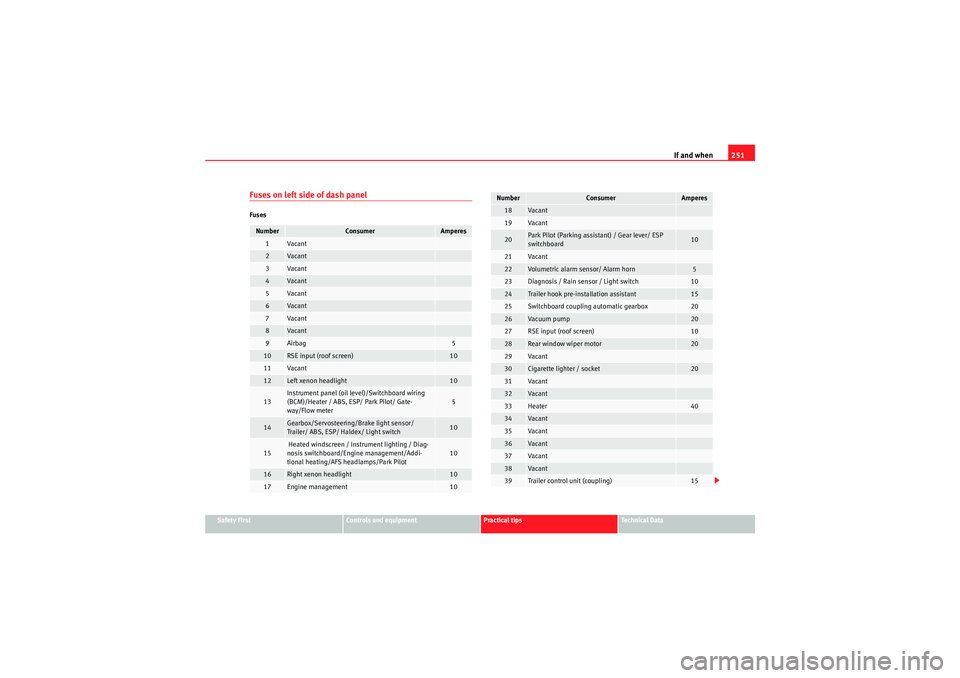
consumer ⇒page 251.
– Take the plastic clip from inside the fuse cover, fit it onto the blown fuse and pull the fuse out.
– Replace the blown fuse (which will have a melted metal strip) with a new fuse of the same ampere rating.
Fuse cover in engine compartment
– Switch off the ignition and its failed electrical component.
– Prise off the fuse cover in the engine compartment by pressing the tabs towards the centre of the cover ⇒fig. 178 .
– Identify the fuse for the failed component ⇒page 251.
– Take the plastic clip from inside the fuse cover (at left-hand end of the dash panel), fit it onto the blown fuse and pull the fuse out.
– Replace the blown fuse (which will have a melted metal strip) with a new fuse of the same ampere rating.
– Carefully fit the fuse cover back on to ensure no water can enter the fuse box.The individual electrical circuits are protected by fuses. The fuses are located
behind a cover at the left-hand end of the dash panel and on the left-hand
side of the engine compartment.
Fig. 177 Left side of dash
panel: Fuse box coverFig. 178 Fuse box cover
in engine compartment
Freetrack_EN.book Seite 249 Donnerstag, 10. September 2009 10:33 10
Page 252 of 294

If and when
250The electric windows are protected by circuit breakers . These reset automat-
ically after a few seconds when the overload (caused for example by frozen
windows) has been corrected.
Fuses colour code
WARNING
Never “repair” damaged fuses and never replace them with fuses with a
higher rating. Failure to comply could result in fire. This could also cause
damage to other parts of the electrical system.
Note
•If a newly replaced fuse blows again after a short time, the electrical
system must be checked by a qualified workshop as soon as possible.
•If you replace a fuse with higher-rating fuse, you could cause damage to
another location in the electrical system.•Always keep some spare fuses in the vehicle. These are available from
SEAT dealers.•Apart from the fuses indicated in the following tables, there are others
which must be replaced by a Technical Service.
Colour
Amperes
light brown
5
Red
10
Blue
15
Ye ll ow
20
Natural (white)
25
Green
30
orange
40
Red
50
white
80
Blue
100
grey
150
violet
200
Freetrack_EN.book Seite 250 Donnerstag, 10. September 2009 10:33 10
Page 253 of 294

If and when251
Safety First
Controls and equipment
Practical tips
Technical Data
Fuses on left side of dash panelFusesNumber
Consumer
Amperes
1
Va can t
2
Va can t
3
Va can t
4
Va can t
5
Va can t
6
Va can t
7
Va can t
8
Va can t
9
Airbag
5
10
RSE input (roof screen)
10
11
Va can t
12
Left xenon headlight
10
13
Instrument panel (oil level)/Switchboard wiring
(BCM)/Heater / ABS, ESP/ Park Pilot/ Gate-
way/Flow meter
5
14
Gearbox/Servosteering/Brake light sensor/
Trailer/ ABS, ESP/ Haldex/ Light switch
10
15
Heated windscreen / Instrument lighting / Diag-
nosis switchboard/Engine management/Addi-
tional heating/AFS headlamps/Park Pilot
10
16
Right xenon headlight
10
17
Engine management
10
18
Va can t
19
Va can t
20
Park Pilot (Parking assistant) / Gear lever/ ESP
switchboard
10
21
Va can t
22
Volumetric alarm sensor/ Alarm horn
5
23
Diagnosis / Rain sensor / Light switch
10
24
Trailer hook pre-installation assistant
15
25
Switchboard coupling automatic gearbox
20
26
Vacuum pump
20
27
RSE input (roof screen)
10
28
Rear window wiper motor
20
29
Va can t
30
Cigarette lighter / socket
20
31
Va can t
32
Va can t
33
Heater
40
34
Va can t
35
Va can t
36
Va can t
37
Va can t
38
Va can t
39
Trailer control unit (coupling)
15
Number
Consumer
Amperes
Freetrack_EN.book Seite 251 Donnerstag, 10. September 2009 10:33 10
Page 254 of 294

If and when
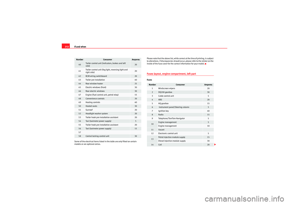
252Some of the electrical items listed in the table are only fitted on certain
models or are optional extras. Please note that the above list, while correct at the time of printing, is subject
to alterations. If discrepancies should occur, please refer to the sticker on the
inside of the fuse cover for the correct information for your model.
Fuses layout, engine compartment, left partFuses
40
Trailer control unit (indicators, brakes and left
side)
20
41
Trailer control unit (fog light, reversing light and
right side)
20
42
BCM wiring switchboard
20
43
Trailer pre-installation
40
44
Rear window heater
25
45
Electric windows (front)
30
46
Rear electric windows
30
47
Engine (Fuel control unit, petrol relay)
15
48
Convenience controls
20
49
Heating controls
40
50
Heated seats
30
51
Sunroof
20
52
Headlight washer system
20
53
Trailer hook pre-installation assistant
20
54
Taxi (taximeter power supply)
5
55
Trailer hook pre-installation assistant
20
56
Taxi (taximeter power supply)
15
5758
Central locking control unit
30
Number
Consumer
Amperes
Number
Consumer
Amperes
1
Windscreen wipers
20
2
DQ200 gearbox
30
3
Cable control unit
5
4
ABS
20
5
AQ gearbox
15
6
Instrument panel/Steering column
5
7
Ignition key
40
8
Radio
15
9
Telephone/TomTom Navigator
5
10
Engine management
5
Engine management
10
11
Vacant
12
Electronic control unit
5
13
Petrol injection module supply
15
Diesel injection module supply
30
14
Coil
20
Freetrack_EN.book Seite 252 Donnerstag, 10. September 2009 10:33 10
Page 255 of 294

If and when253
Safety First
Controls and equipment
Practical tips
Technical Data
Bulb changeGeneral notesBefore changing any bulb, first turn off the failed component.
Do not touch the bulb glass. Fingerprints vaporise in the heat, causing a
reduction in the bulb life and condensation on the mirror surface, thus
reducing efficiency.
A bulb should only be replaced by one of the sam e type. The type is inscribed
on the bulb, either on the glass part or on the base.
It is highly recommended to keep a box of spare bulbs in the vehicle. At the
very least, the following spare bulbs, which are essential for road safety,
should be kept in the vehicle.
Main headlights
Dipped beam - H7
Main beam - H1
Position - W5W
Indicator - PY21W
Xenon headlights
22)/self-directing
Dipped and full beam - D1S
23)
Daylight - P21W SLL
Position W5W
Indicators PY21W
15
Engine management
5
Pump relay
10
16
Right lighting
30
17
Horn
15
18
Vaca n t
19
Clean
30
20
Water pump
10
Pressure sensor pump for 1.8 engine
20
21a)
Lambda probe
15
22
Brake pedal, speed sensor
5
23a)
Engine management
5
Engine management
10
Engine management
15
24
AKF, gearbox valve
10
25a)
ABS pump
40
26
Left lighting
30
27a)
Engine management
40
Engine management
50
28
Vaca n t
29a)
Electric windows (front and back)
50
Electric windows (front)
30
30
Ignition key
50
a)Ampere rating according to motorisationNumber
Consumer
Amperes
22)On this type of headlight, the bulb changes must be made by the SEAT dealer, given
that complex elements must be removed from the vehicle and a reset must be made
on the automatic control system incorporated.23)The Xenon bulbs discharge 2.5 times the light flux and have an average lifespan of 5
times more than that of halogen bulbs, this means that, except due to unusual circum-
stances, there is no need to change the bulbs for the whole life of the vehicle.
Freetrack_EN.book Seite 253 Donnerstag, 10. September 2009 10:33 10
Page 256 of 294

If and when
254Fog lights
Fog lights - H3
Fixed rear light
Stop/Position - P21W
24)
Indicator - P21W
Rear tailgate light unit
Fog light (driver's side) - P21W
Reverse (passenger's side) - P21W
Position - W5W
Side indicator
Side indicator - W5W
Registration plate light
Registration plate light - C5W
Note
•Depending on weather conditions (cold or wet), the front lights, the fog
lights, the rear lights and the indicators may be temporarily misted. This has
no influence on the life expectancy of the lighting system. By switching on the
lights, the area through which the beam of light is projected will quickly be
demisted. However, the edges may continue to be misted.•Please check at regular intervals that all lighting (especially the exterior
lighting) on your vehicle is functioning properly. This is not only in the interest
of your own safety, but also in that of all other road users.•Due to the difficulty in accessing the lamps, any replacement work should
be done by a SEAT dealer. However, the following is a description of how to
change the lamps except for the fog lights* and interior lamps.
Main headlight lamps
Indicator
Dipped headlights
Main beam headlights
Side lights
24)Electronically controlled single filament bulb for Stop/side bulbs. If the bulb blows it
will not work in either position or Stop.
Fig. 179 Main headlight
lamps
AAABACAD
Freetrack_EN.book Seite 254 Donnerstag, 10. September 2009 10:33 10
Page 257 of 294

If and when255
Safety First
Controls and equipment
Practical tips
Technical Data
Turn signal lamps– Raise the bonnet.
– Rotate the lamp holder ⇒ fig. 180 to the left and pull.
– Remove the bulb by pressing on the lamp holder and rotating at the same time to the left.
– Installation is done in the reverse order.
Dipped beam lights– Raise the bonnet.
Fig. 180 Turn signal
lamps
AA
Fig. 181 Dipped head-
lightsFig. 182 Dipped head-
lights
Freetrack_EN.book Seite 255 Donnerstag, 10. September 2009 10:33 10
Page 258 of 294

If and when
256
– Remove the loops ⇒page 255, fig. 181 in the direction of
the arrow and remove the cover.
– Remove the connector ⇒page 255, fig. 182 from the bulb.
– Disengage the retainer spring ⇒page 255, fig. 182 pressing
inwards to the right.
– Extract the bulb and fit the replacement so that the rim of the attachment plate is on the reflector cut-out.Main beam lights
– Raise the bonnet.
– Remove the cover ⇒fig. 183 by pulling on this.
– Remove the connector ⇒fig. 184 from the bulb.
–Press the spring ⇒fig. 184 inwards and to the right.
– Extract the bulb and fit the replacement so that it sits correctly into the cut-out on the reflector.
– Installation is done in the reverse order.
A1
A2
A3
Fig. 183 Main beam
headlights
Fig. 184 Main beam
headlights
AC
A1
A2
Freetrack_EN.book Seite 256 Donnerstag, 10. September 2009 10:33 10
Page 259 of 294

If and when257
Safety First
Controls and equipment
Practical tips
Technical Data
Side lights– Raise the bonnet.
– Remove the cover ⇒fig. 185 by pulling on this. –Extract the lamp holder
⇒fig. 186 outwards.
– Replace the bulb by pulling this out and inserting the replace- ment.
– Installation is done in the reverse order.
Rear lights•On the body
– Indicator, side and brake light•On the tailgate
– Left side: position and fog lights.
– Right side: reverse and position.
Fig. 185 Side lightsFig. 186 Side lights
AD
A1
Freetrack_EN.book Seite 257 Donnerstag, 10. September 2009 10:33 10
Page 260 of 294

If and when
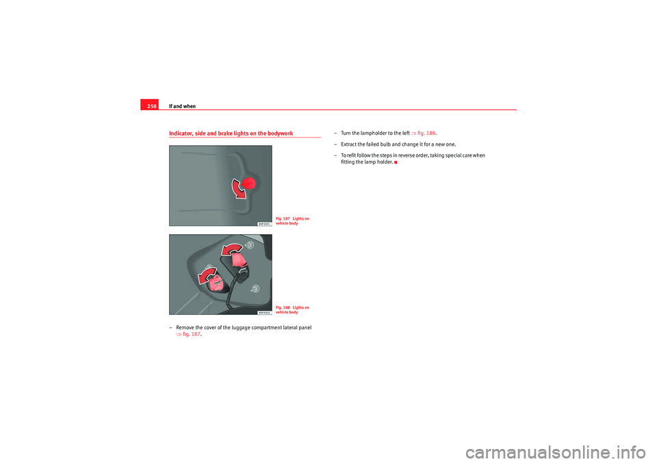
258Indicator, side and brake lights on the bodywork– Remove the cover of the luggage compartment lateral panel
⇒fig. 187 . – Turn the lampholder to the left
⇒fig. 188.
– Extract the failed bulb and change it for a new one.
– To refit follow the steps in reverse order, taking special care when fitting the lamp holder.
Fig. 187 Lights on
vehicle bodyFig. 188 Lights on
vehicle body
Freetrack_EN.book Seite 258 Donnerstag, 10. September 2009 10:33 10