light Seat Altea Freetrack 2012 Owner's Manual
[x] Cancel search | Manufacturer: SEAT, Model Year: 2012, Model line: Altea Freetrack, Model: Seat Altea Freetrack 2012Pages: 297, PDF Size: 4.31 MB
Page 263 of 297

261
If and when
Turn signal bulbs
Fig. 179 Turn signal
– Raise the bonnet.
– Rotate the bulb holder ⇒ fig. 179 A
to the left and pull.
– Remove the bulb by pressing on the bulb holder and rotating at
the same time to the left.
– Installation is done in the reverse order. Dipped lights
Fig. 180 Dipped beam
headlights
Fig. 181 Dipped beam
headlights
– Raise the bonnet.
– Remove the loops ⇒ fig. 180 1
in the direction of the arrow
and remove the cover.
Safety FirstOperating InstructionsPractical TipsTechnical Specifications
Page 264 of 297
262If and when
–Remove the connector ⇒ fig. 181 2
from the bulb.
– Unclip the retainer spring ⇒ fig. 181 3
pressing inwards to the
right.
– Extract the bulb and fit the replacement so that the rim of the
attachment plate is on the reflector cut-out.
Main beam lights
Fig. 182 Main beam
headlights
Fig. 183 Main beam
headlights
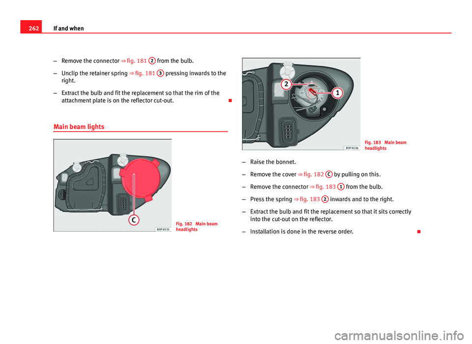
– Raise the bonnet.
– Remove the cover ⇒ fig. 182 C
by pulling on this.
– Remove the connector ⇒ fig. 183 1
from the bulb.
– Press the spring ⇒ fig. 183 2
inwards and to the right.
– Extract the bulb and fit the replacement so that it sits correctly
into the cut-out on the reflector.
– Installation is done in the reverse order.
Page 265 of 297

263
If and when
Side lights
Fig. 184 Side lights
Fig. 185 Side lights
– Raise the bonnet.
– Remove the cover ⇒ fig. 184 D
by pulling on this. –
Extract the bulb holder ⇒ fig. 185 1
outwards.
– Replace the bulb by pulling it out and inserting the replace-
ment.
– Installation is done in the reverse order.
Tail lights
On the body
– Turn signal, side and brake light
On the tailgate
– Left side: side and fog lights.
– Right side: side and reverse.
Safety FirstOperating InstructionsPractical TipsTechnical Specifications
Page 266 of 297
264If and when
Turn signal, side and brake lights on the body
Fig. 186 Lights on vehi-
cle body
Fig. 187 Lights on vehi-
cle body
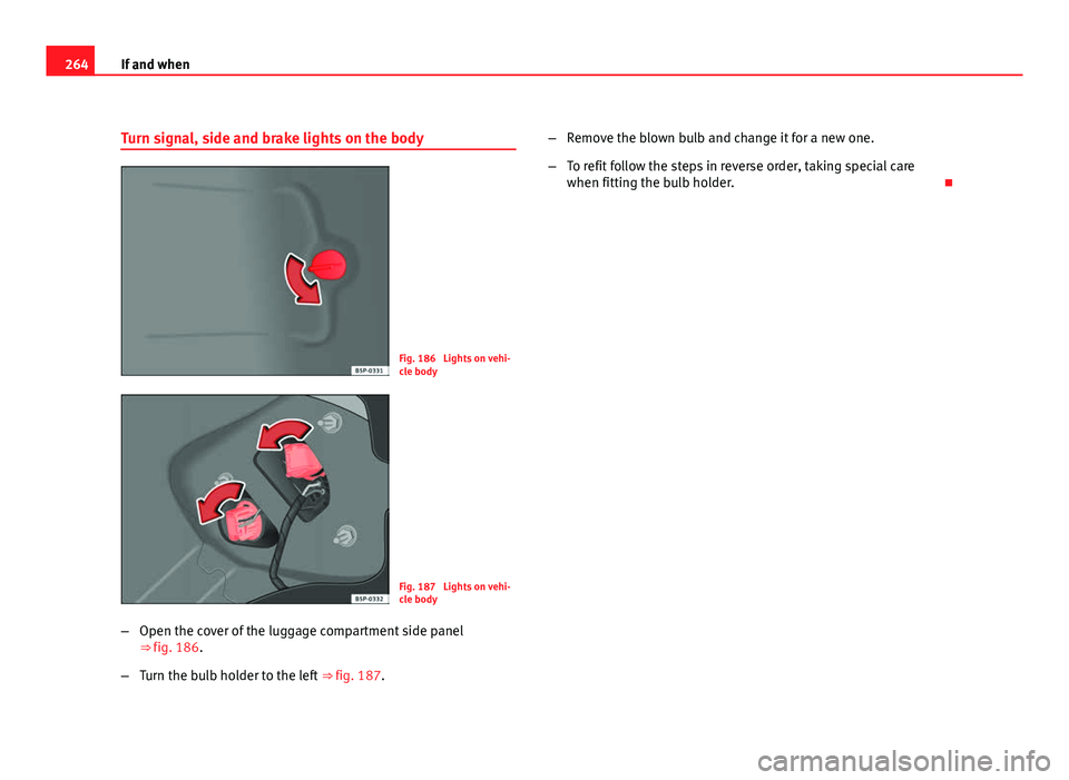
– Open the cover of the luggage compartment side panel
⇒ fig. 186.
– Turn the bulb holder to the left ⇒ fig. 187. –
Remove the blown bulb and change it for a new one.
– To refit follow the steps in reverse order, taking special care
when fitting the bulb holder.
Page 267 of 297

265
If and when
Position light, fog light and reverse light on the tailgate
Fig. 188 Lights on the
tailgate
Fig. 189 Side lights
Side lights
– Open the tailgate. –
Pull the cover off.
– Take the bulb holder out pressing on the securing tabs and ex-
tract it outwards.
– Remove the blown bulb and replace it with another.
– To refit follow the steps in reverse order, taking special care
when fitting the bulb holder.
Fog light and reverse light
– Open the tailgate.
– Pull the cover off.
– Turn the bulb holder to the left.
– Remove the blown bulb and replace it with another.
– Installation is done in the reverse order.
Safety FirstOperating InstructionsPractical TipsTechnical Specifications
Page 268 of 297
266If and when
Side turn signals
Fig. 190 Side turn signal
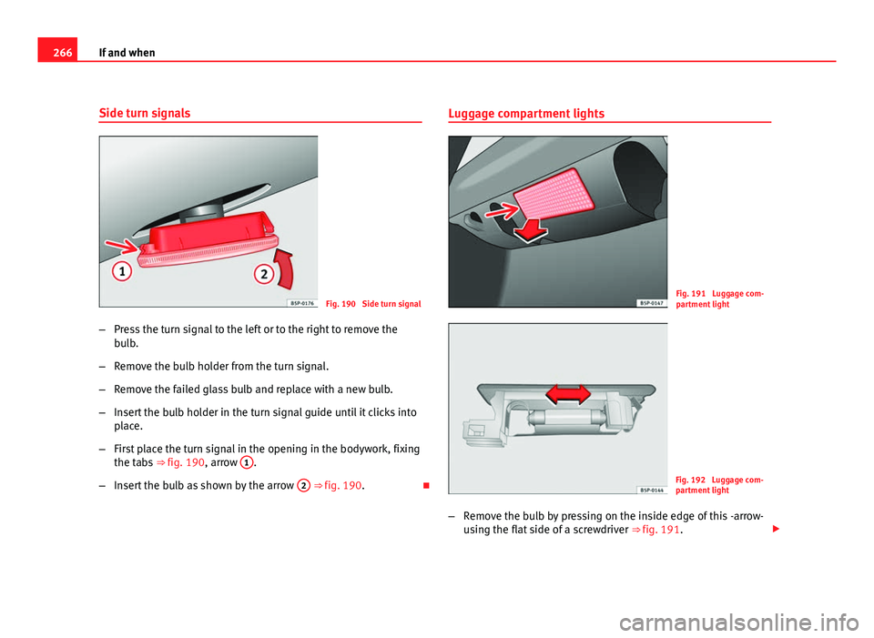
– Press the turn signal to the left or to the right to remove the
bulb.
– Remove the bulb holder from the turn signal.
– Remove the failed glass bulb and replace with a new bulb.
– Insert the bulb holder in the turn signal guide until it clicks into
place.
– First place the turn signal in the opening in the bodywork, fixing
the tabs ⇒ fig. 190, arrow 1
.
– Insert the bulb as shown by the arrow 2
⇒ fig. 190.Luggage compartment lights
Fig. 191 Luggage com-
partment light
Fig. 192 Luggage com-
partment light
– Remove the bulb by pressing on the inside edge of this -arrow-
using the flat side of a screwdriver ⇒ fig. 191.
Page 269 of 297

267
If and when
– Press the bulb sideways and remove it from the housing
⇒ fig. 192.
Registration light
Fig. 193 Number plate
light
Fig. 194 Number plate
light –
To remove the light cover, unscrew the bolts ⇒ fig. 193.
– Remove the bulb, moving it in the direction of the arrow and
outwards ⇒ fig. 194.
– Installation is done in the reverse order.
Safety FirstOperating InstructionsPractical TipsTechnical Specifications
Page 270 of 297
268If and when
Sun visor light
Fig. 195 Removing sun
visor light
Fig. 196 Removing sun
visor light
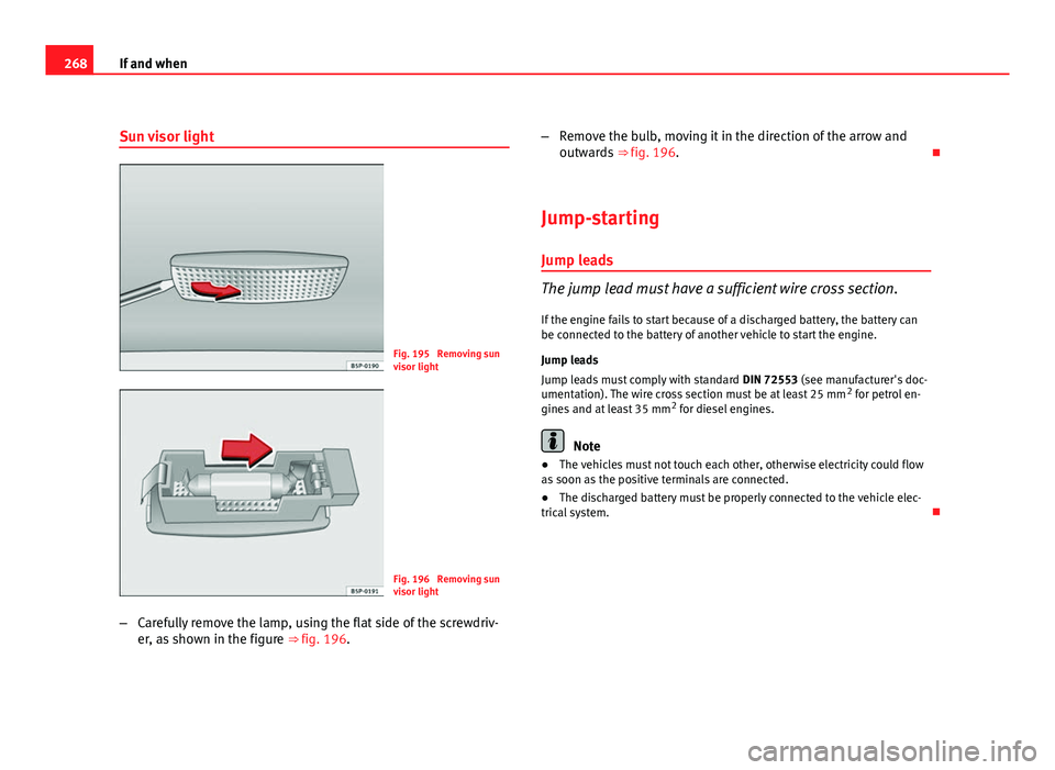
– Carefully remove the lamp, using the flat side of the screwdriv-
er, as shown in the figure ⇒ fig. 196. –
Remove the bulb, moving it in the direction of the arrow and
outwards ⇒ fig. 196.
Jump-starting
Jump leads
The jump lead must have a sufficient wire cross section. If the engine fails to start because of a discharged battery, the battery can
be connected to the battery of another vehicle to start the engine.
Jump leads
Jump leads must comply with standard DIN 72553 (see manufacturer's doc-
umentation). The wire cross section must be at least 25 mm 2
for petrol en-
gines and at least 35 mm 2
for diesel engines.
Note
● The vehicles must not touch each other, otherwise electricity could flow
as soon as the positive terminals are connected.
● The discharged battery must be properly connected to the vehicle elec-
trical system.
Page 271 of 297

269
If and when
How to jump start: description
Fig. 197 Diagram for
connecting jump leads if
the vehicle providing as-
sistance the current is
not fitted with the Start-
Stop system: flat battery A
and battery providing
current B.
Fig. 198 Diagram for
connecting jump leads if
the vehicle providing as-
sistance is fitted with the
Start-Stop system: flat
battery A
and battery
providing current B.
Jump lead terminal connections
1. Switch off the ignition of both vehicles ⇒
.2. Connect one end of the
red jump lead to the positive terminal
⇒ fig. 197 +
or ⇒
fig. 198 + of the vehicle with the flat bat-
tery A.
3. Connect the other end of the red jump lead to the positive ter-
minal +
in the vehicle providing assistance B.
4. On vehicles with no Start-Stop system , connect one end of the
black jump lead to the negative terminal -
in the vehicle pro-
viding assistance B ⇒ fig. 197.
5. On vehicles with the Start-Stop system , connect one end of the
black jump lead X
to a suitable ground terminal, to a solid
metal part bolted to the engine block or to the engine block it-
self ⇒ fig. 198.
6. Connect the other end of the black jump lead X
to a solid met-
al component bolted to the engine block or to the engine block
itself of the vehicle with the flat battery. Do not connect it to a
point near the battery A
.
7. Position the leads in such a way that they cannot come into contact with any moving parts in the engine compartment.
Starting
8. Start the engine of the vehicle with the boosting battery and let it run at idling speed.
9. Start the engine of the vehicle with the flat battery and wait one or two minutes until the engine is running.
Removing the jump leads
10. Before you remove the jump leads, switch off the headlights (if they are switched on).
Safety FirstOperating InstructionsPractical TipsTechnical Specifications
Page 272 of 297
270If and when
11. Turn on the heater blower and heated rear window in the vehi-
cle with the flat battery. This helps minimise voltage peaks
which are generated when the leads are disconnected.
12. When the engine is running, disconnect the leads in reverse order to the details given above.
Connect the battery clamps so they have good metal-to-metal contact with
the battery terminals.
If the engine fails to start, switch off the starter after about 10 seconds and
try again after about half a minute.
WARNING
● Please note the safety warnings referring to working in the engine
compartment ⇒ page 219, Working in the engine compartment.
● The battery providing assistance must have the same voltage as the
flat battery (12V) and approximately the same capacity (see imprint on
battery). Failure to comply could result in an explosion.
● Never use jump leads when one of the batteries is frozen. Danger of
explosion! Even after the battery has thawed, battery acid could leak and
cause chemical burns. If a battery freezes, it should be replaced.
● Keep sparks, flames and lighted cigarettes away from batteries, dan-
ger of explosion. Failure to comply could result in an explosion.
● Observe the instructions provided by the manufacturer of the jump
leads.
● Do not connect the negative cable from the other vehicle directly to
the negative terminal of the flat battery. The gas emitted from the battery
could be ignited by sparks. Danger of explosion.
● Do not attach the negative cable from the other vehicle to parts of the
fuel system or to the brake line.
WARNING (Continued)
● The non-insulated parts of the battery clamps must not be allowed to
touch. The jump lead attached to the positive battery terminal must not
touch metal parts of the vehicle, this can cause a short circuit.
● Position the leads in such a way that they cannot come into contact
with any moving parts in the engine compartment.
● Do not bend over the batteries. This could result in chemical burns.
Note
The vehicles must not touch each other, otherwise electricity could flow as
soon as the positive terminals are connected.