change Seat Altea XL 2014 Owner's Guide
[x] Cancel search | Manufacturer: SEAT, Model Year: 2014, Model line: Altea XL, Model: Seat Altea XL 2014Pages: 321, PDF Size: 4.52 MB
Page 144 of 321
142Seats and storage
WARNING
Always keep the storage compartment closed while the vehicle is in mo-
tion to reduce the risk of injury from the armrest during a sudden braking
manoeuvre or in the event of an accident.
Note
The CD changer is located in this compartment.
Storage compartment under the front seats*
There is a storage compartment with a cover under each
front seat.
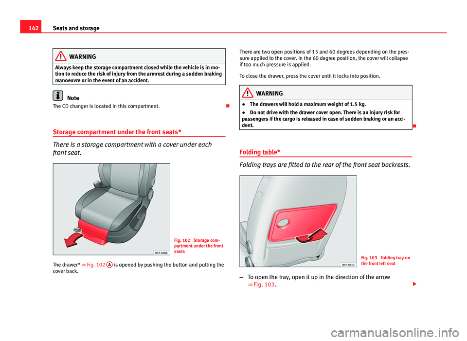
Fig. 102 Storage com-
partment under the front
seats
The drawer* ⇒ Fig. 102 A
is opened by pushing the button and putting the
cover back. There are two open positions of 15 and 60 degrees depending on the pres-
sure applied to the cover. In the 60 degree position, the cover will collapse
if too much pressure is applied.
To close the drawer, press the cover until it locks into position.
WARNING
● The drawers will hold a maximum weight of 1.5 kg.
● Do not drive with the drawer cover open. There is an injury risk for
passengers if the cargo is released in case of sudden braking or an acci-
dent.
Folding table*
Folding trays are fitted to the rear of the front seat backrests.
Fig. 103 Folding tray on
the front left seat
– To open the tray, open it up in the direction of the arrow
⇒
Fig. 103.
Page 151 of 321
149
Seats and storage
The table in the right-hand compartment is fitted in the left-hand slot of the
front of the mobile storage compartment and the table in the left-hand com-
partment is fitted in the right-hand slot.
The tables have two positions for use and cannot be interchanged.
WARNING
● The mobile stowage compartment supports a maximum load of 5 kg.
Do not overload.
● Do not drive when the cover of the mobile storage compartment is
open.
● Do not drive when the tables are set up for use.
● When the vehicle is moving, keep the tables stored inside the mobile
storage compartment with the cover closed, and likewise when they are
not in use
● Never place hot drinks in the cup holders. The drink may spill and
cause burns when the vehicle is moving.
● Do not leave cans in the cup holders when the vehicle is in motion,
there is a danger that the can may be flung around the vehicle and cause
injury.
● Make sure that the mounting plate is correctly clipped onto the cush-
ion frame.
● When the plate is not in use, store inside the storage compartment.
● When the mobile storage compartment is not in use, it should always
be fastened by the storage net in the luggage compartment.
Note
● Check that the mobile storage compartment is correctly fitted, pulling it
forwards by the front glove compartment and checking that both safety
clips are correctly clipped onto the rings. Fitting and removal
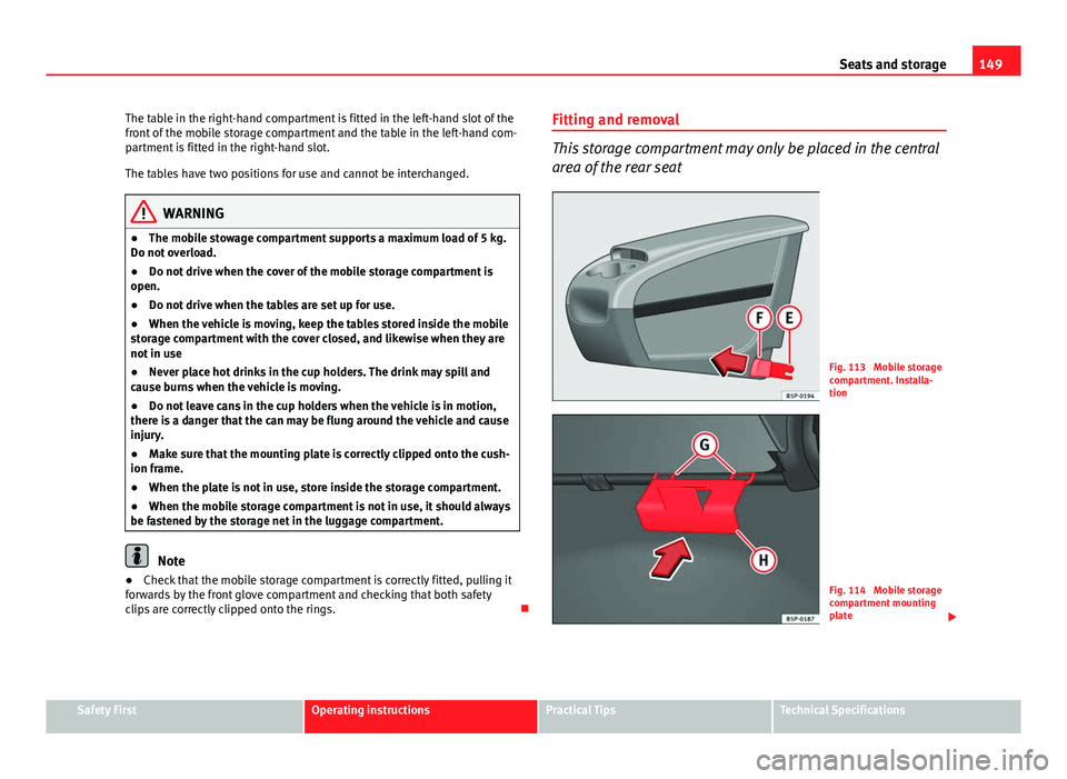
This storage compartment may only be placed in the central
area of the rear seat
Fig. 113 Mobile storage
compartment. Installa-
tion
Fig. 114 Mobile storage
compartment mounting
plate
Safety FirstOperating instructionsPractical TipsTechnical Specifications
Page 157 of 321
155
Seats and storage
– Distribute the load as evenly as possible.
– Place heavy objects as far forward in the luggage compartment
as possible.
– Secure luggage in the luggage compartment with suitable
straps on the fastening rings.
WARNING
● Loose luggage and other loose items in the vehicle can cause serious
injuries.
● Loose objects in the luggage compartment can suddenly move and
change the way the vehicle handles.
● During sudden manoeuvres or accidents, loose objects in the passen-
ger compartment can be flung forward, injuring vehicle occupants.
● Always store objects in the luggage compartment and secure with
suitable straps. This is especially important for heavy objects.
● When you transport heavy objects, always take in account that a
change in the centre of gravity can also cause changes in vehicle han-
dling.
● Please observe information on safe driving ⇒ page 7, Safe driving.
CAUTION
Hard objects on the shelf could chafe against the wires of the heating ele-
ment in the rear window and cause damage.
Note
The ventilation slots in front of the rear side windows must not be covered
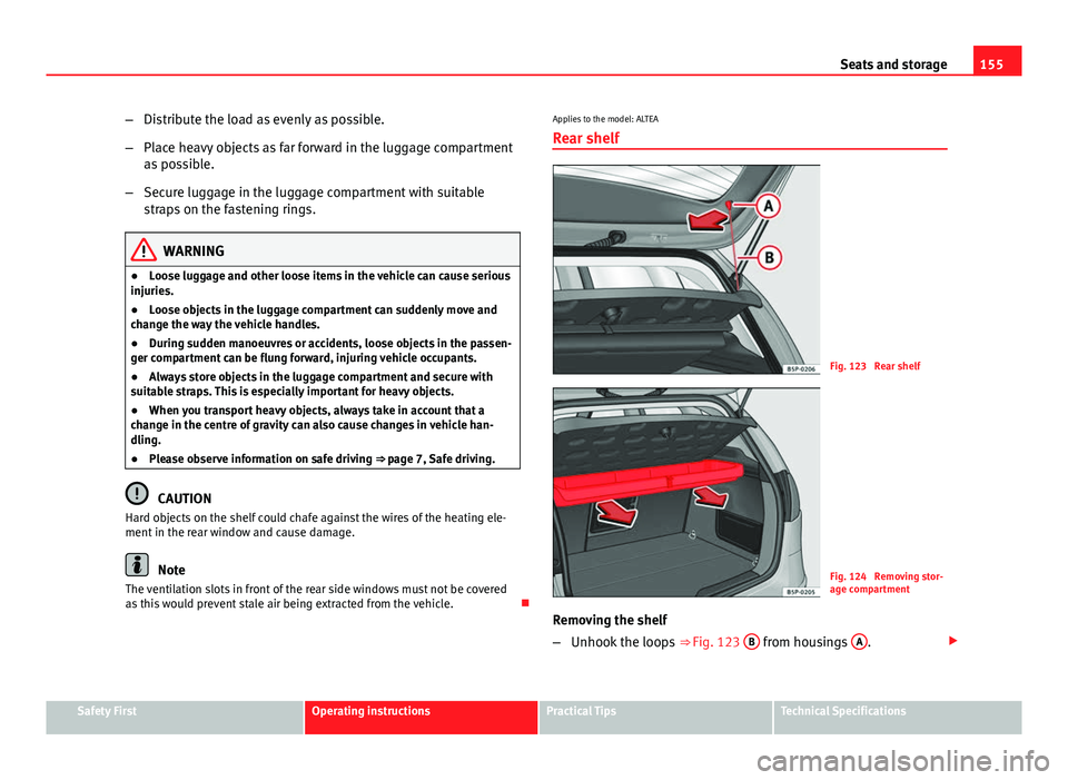
as this would prevent stale air being extracted from the vehicle. Applies to the model: ALTEA
Rear shelf
Fig. 123 Rear shelf
Fig. 124 Removing stor-
age compartment
Removing the shelf
– Unhook the loops ⇒ Fig. 123 B
from housings A.
Safety FirstOperating instructionsPractical TipsTechnical Specifications
Page 160 of 321
158Seats and storage
–Pull the net from underneath between the backrest and the fold-
ing tray and fit it to the slots in the roof, first the right then the
left ⇒ Fig. 127.
– Hook the belts into the front fastening rings to tense the net
⇒ Fig. 128.
Roof rack*
Please observe the following points if you intend to carry loads on the roof:
● For safety reasons, only luggage racks and accessories supplied by SEAT
Official Services are recommended.
● It is essential that you follow the assembly instructions included with
the bars exactly, being especially careful to position the luggage compart-
ment cover bars on the special housings, you must also respect their posi-
tion according to the direction of travel indicated in the assembly manual.
Not following these instructions may cause marks on the bodywork and the
longitudinal bars.
● Pay special attention to the tightening torque of the attachment bolts
and check them following a short journey. If necessary, retighten the bolts
and check them at regular intervals.
● Distribute the load evenly. A maximum load of 40 kg only is permitted
for each roof rack system support bar, the load must be distributed evenly
along the entire length. However, the maximum load permitted for the en-
tire roof (including the support system) of 75 kg must not be exceeded nor
should the total weight of the vehicle be exceeded. See the Technical Data
section.
● When transporting heavy or large objects on the roof, any change in the
normal vehicle behaviour due to a change in the centre of gravity or an in- creased wind resistance must be taken into account. For this reason, a suit-
able speed and driving style must be used.
●
For those vehicles fitted with a sliding/tilting sunroof*, ensure that it
does not interfere with the load on the roof rack system when opened.
Page 168 of 321
166Air conditioning
Viewing Climatronic information
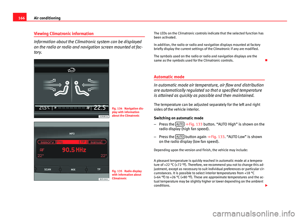
Information about the Climatronic system can be displayed
on the radio or radio and navigation screen mounted at fac-
tory.
Fig. 134 Navigation dis-
play with information
about the Climatronic
Fig. 135 Radio display
with information about
Climatronic The LEDs on the Climatronic controls indicate that the selected function has
been activated.
In addition, the radio or radio and navigation displays mounted at factory
briefly display the current settings of the Climatronic if any are modified.
The symbols used on the radio or radio and navigation displays are the
same as the symbols used for the Climatronic controls.
Automatic mode
In automatic mode air temperature, air flow and distribution
are automatically regulated so that a specified temperature
is attained as quickly as possible and then maintained. The temperature can be adjusted separately for the left and right
sides of the vehicle interior.
Switching on automatic mode
– Press the AUTO
⇒
Fig. 133 button. “AUTO High” is shown on the
radio display (high fan speed).
– Press the AUTO
button again ⇒ Fig. 133. “AUTO Low” is shown
on the radio display (low fan speed).
Depending upon the version and finish, the vehicle may include:
A pleasant temperature is quickly reached in automatic mode at a tempera-
ture of +22 °C (+72 °F). Therefore, we recommend you not to change this ad-
justment, except as necessary to suit individual preferences or particular cir-
cumstances. It is possible to select interior temperatures from +18 °C
(+64 °F) to +26 °C (+80 °F). These are approximate temperatures and the ac-
tual temperature may be slightly higher or lower depending on the ambient
conditions.
Page 170 of 321
168Air conditioning
Switching on manual mode
–To enter manual mode, press one of the buttons ⇒ Fig. 136 1
to 5 or press the air flow control 10. The selected function is
shown on the radio or navigator display.
Temperature
There are separate temperature selectors for the left and right sides of the
vehicle interior. The selected temperature is displayed above the selector. It
is possible to select interior temperatures from +18 °C (+64 °F) to +26 °C
(+80 °F). These are approximate temperatures and the actual temperature
may be slightly higher or lower depending on the ambient conditions.
If you select temperatures below +18 °C (+64 °F) the indication LO will ap-
pear on the screen. In this setting the system runs at maximum cooling out-
put and the temperature is not regulated.
If you select temperatures above +26 °C (+80 °F) the indication HI will ap-
pear on the screen. In this setting the system runs at maximum heating out-
put and the temperature is not regulated.
Blower
The air flow may be adjusted freely using the control 10
. Always have the
blower running at a low setting to ensure a constant flow of fresh air into
the vehicle. Pushing the button to the minimum -1, turns the Climatronic
off.
Air distribution
The air distribution is adjusted using the buttons
, and . It is also
possible to open and close some of the air vents separately.
Switching the air conditioning on and off
When the AC
button is on (LED lit), the air conditioning system is on.
When the AC
button is off (LED off), the air conditioning system is off. When the
AC
button is off, the air conditioning system is switched off to
save fuel. The temperature continues to self-regulate. The set temperature
can then only be reached if it is higher than the outside temperature.
Driver and passenger temperature control
The SYNC
button controls the synchronisation of the 2 Climatronic climate
zones.
When the SYNC
button is off (LED off), the climate zone of the Climatronic is
personalised. For example: driver side temperature +22 °C (+72 °F) and pas-
senger side temperature +24 °C (+75 °F).
When the SYNC
button is on (LED lit), the climate zone of the Climatronic is
synchronised. For example: driver side temperature +22 °C (+72 °F) and
passenger side temperature +22 °C (+72 °F).
If the SYNC
button is on and the passenger side temperature is changed,
the function is automatically deactivated.
Air recirculation mode
Air recirculation mode prevents fumes or unpleasant smells
from coming from the outside. – Press the button
⇒ Fig. 136
2 to switch air recirculation
mode on or off. It is switched on if the following symbol appears
in the display .
Air recirculation mode prevents strong odours in the ambient air from enter-
ing the vehicle interior, for example when passing through a tunnel or in a
traffic jam.
With low outside temperatures, the air recirculation increases the effective-
ness of the heating system by heating the air inside the vehicle rather than
the air from outside.
Page 171 of 321
169
Air conditioning
With high outside temperatures, the air recirculation increases the effective-
ness of the air conditioning system by cooling the air inside the vehicle
rather than the ambient air.
If the windscreen air output is on and the air recirculation mode is pressed,
this remains active. When the recirculation mode is on, if the air distribution
towards the windscreen mode is selected, the recirculation mode is deacti-
vated. For safety reasons, the air recirculation mode should not be connec-
ted.
WARNING
In air recirculation mode, no cold air from the outside enters the vehicle
interior. If the air conditioning system is switched off, the windows can
quickly mist over. Therefore, never leave the air recirculation mode
switched on for a long time (risk of accident).
General notes
Pollution filter
The pollution filter (a combined particulate filter and active carbon filter)
serves as a barrier against impurities in the outside air, including dust and
pollen.
For the air conditioner to work with maximum efficiency, the pollution filter
must be replaced at the intervals specified in the Service Plan.
If the filter loses efficiency prematurely due to use in areas reaching very
high pollution levels, the pollen filter must be changed more frequently
than stated in the Service Schedule.
Air conditioner
When the air conditioning system is switched on, not only the temperature,
but also the air humidity in the vehicle interior is reduced. This improves comfort for the vehicle occupants and prevents misting of the windows
when the ambient air humidity is high.
If the air conditioning system cannot be switched on this may be caused by
the following reasons:
●
The engine is not running.
● The AC
button is disconnected.
● The outside temperature is lower than approximately +3 °C (+37 °F).
● The air conditioning system compressor has been temporarily switched
off because the engine coolant temperature is too high.
● The air conditioner fuse is faulty.
● Another fault in the vehicle. Have the air conditioner checked by a speci-
alised workshop.
CAUTION
● If you suspect that the air conditioner is damaged, switch it off with but-
ton AC
to prevent further damage and have it checked by a specialised
workshop.
● Repairs to the air conditioner require specialist knowledge and special
tools. Therefore, we recommend you to take the vehicle to a specialised
workshop.
Note
● If the humidity and temperature outside the vehicle are high, condensa-
tion can drip off the evaporator in the cooling system and so forming a pud-
dle underneath the vehicle. This is completely normal and there is no need
to suspect a leak.
● Keep the air intake slots in front of the windscreen free of snow, ice and
leaves to ensure heating and cooling are not impaired, and to prevent the
windows from misting over.
● The air from the vents flows through the vehicle interior and is extracted
by slots designed for this purpose. Therefore, do not cover these slots with
items of clothing or other objects.
Safety FirstOperating instructionsPractical TipsTechnical Specifications
Page 184 of 321
182Driving
Manual gearbox
Driving with a manual gearbox
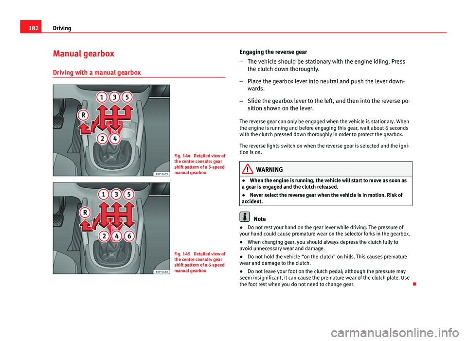
Fig. 144 Detailed view of
the centre console: gear
shift pattern of a 5-speed
manual gearbox
Fig. 145 Detailed view of
the centre console: gear
shift pattern of a 6-speed
manual gearbox Engaging the reverse gear
–
The vehicle should be stationary with the engine idling. Press
the clutch down thoroughly.
– Place the gearbox lever into neutral and push the lever down-
wards.
– Slide the gearbox lever to the left, and then into the reverse po-
sition shown on the lever.
The reverse gear can only be engaged when the vehicle is stationary. When
the engine is running and before engaging this gear, wait about 6 seconds
with the clutch pressed down thoroughly in order to protect the gearbox.
The reverse lights switch on when the reverse gear is selected and the igni-
tion is on.
WARNING
● When the engine is running, the vehicle will start to move as soon as
a gear is engaged and the clutch released.
● Never select the reverse gear when the vehicle is in motion. Risk of
accident.
Note
● Do not rest your hand on the gear lever while driving. The pressure of
your hand could cause premature wear on the selector forks in the gearbox.
● When changing gear, you should always depress the clutch fully to
avoid unnecessary wear and damage.
● Do not hold the vehicle “on the clutch” on hills. This causes premature
wear and damage to the clutch.
● Do not leave your foot on the clutch pedal; although the pressure may
seem insignificant, it can cause the premature wear of the clutch plate. Use
the foot rest when you do not need to change gear.
Page 185 of 321
183
Driving
Automatic gearbox/DSG automatic gearbox* Selector lever positions
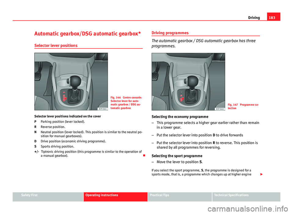
Fig. 146 Centre console:
Selector lever for auto-
matic gearbox / DSG au-
tomatic gearbox
Selector lever positions indicated on the cover Parking position (lever locked).
Reverse position.
Neutral position (lever locked). This position is similar to the neutral po-
sition for manual gearboxes).
Drive position (economic driving programme).
Sports driving position.Tiptronic driving position (this programme is similar to the operation of
a manual gearbox).
P
R
N
D
S
+/- Driving programmes
The automatic gearbox / DSG automatic gearbox has three
programmes.
Fig. 147 Programme se-
lection
Selecting the economy programme
– This programme selects a higher gear earlier rather than remain
in a lower gear.
– Put the selector lever into position D to drive forwards
– Put the selector lever into position R to reverse. This position is
shared by all programmes for reversing.
Selecting the sport programme
– Move the lever to position S.
If you select the sport programme, S, the programme is designed for a
sports mode, that is, a programme which changes up at higher engine
Safety FirstOperating instructionsPractical TipsTechnical Specifications
Page 186 of 321
184Driving
speeds to use the full power of the engine. This programme is not recom-
mended for use on the motorway or in the city.
Selecting the manual programme (tiptronic)
This programme allows driving similar to a manual gearbox.
This programme may be accessed using the selector lever or from the steer-
ing wheel controls when this option is fitted ⇒ page 186.
Selector lever locking
The selector lever lock prevents gears from being engaged
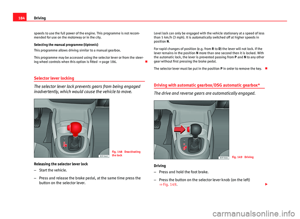
inadvertently, which would cause the vehicle to move.
Fig. 148 Deactivating
the lock
Releasing the selector lever lock
– Start the vehicle.
– Press and release the brake pedal, at the same time press the
button on the selector lever. Level lock can only be engaged with the vehicle stationary at a speed of less
than 5 km/h (3 mph). It is automatically switched off at higher speeds in
position N.
For rapid changes of position (e.g. from
R to D) the lever will not lock. If the
lever remains in the position N more than one second then it is locked. With
the automatic lock, the lever is prevented passing from P and N to any other
gear without first pressing the brake pedal.
The selector lever must be put in the position P in order to remove the key.
Driving with automatic gearbox/DSG automatic gearbox*
The drive and reverse gears are automatically engaged.
Fig. 149 Driving
Driving
– Press and hold the foot brake.
– Press the button on the selector lever knob (on the left)
⇒ Fig. 149.