start stop button Seat Altea XL 2014 Owner's Manual
[x] Cancel search | Manufacturer: SEAT, Model Year: 2014, Model line: Altea XL, Model: Seat Altea XL 2014Pages: 321, PDF Size: 4.52 MB
Page 57 of 321
55
Cockpit
Operating instructions Cockpit
Overview Overview of the dash panel
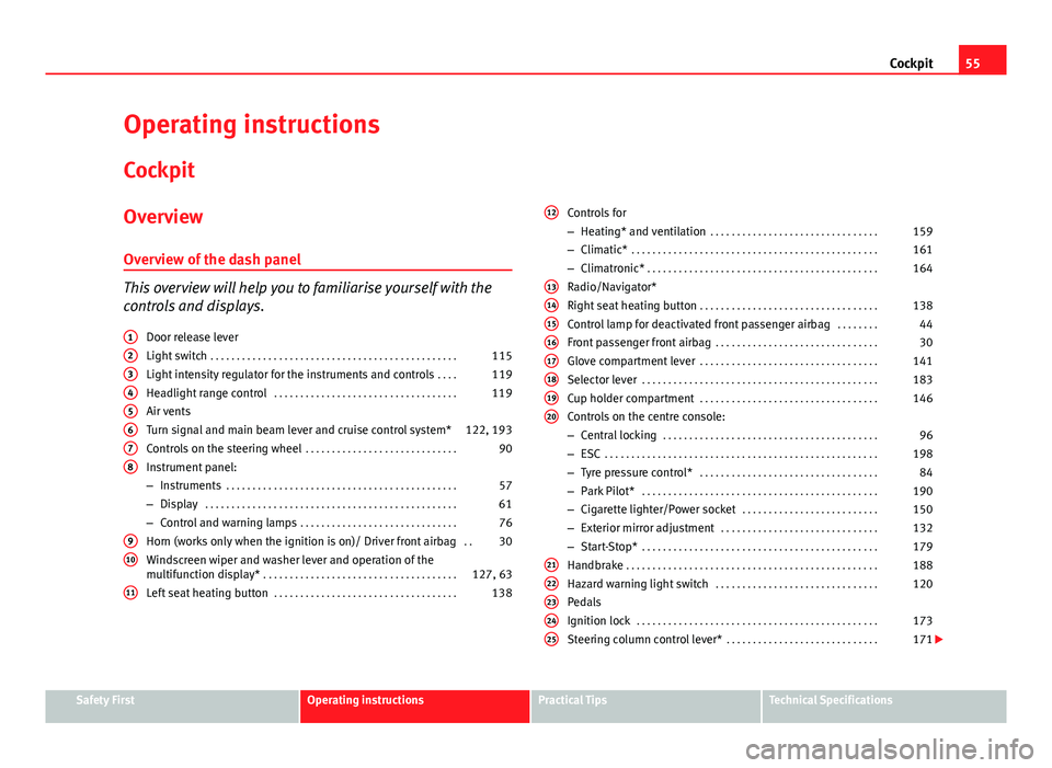
This overview will help you to familiarise yourself with the
controls and displays. Door release lever
Light switch . . . . . . . . . . . . . . . . . . . . . . . . . . . . . . . . . . . . . . . . . . . . . . . 115
Light intensity regulator for the instruments and controls . . . .119
Headlight range control . . . . . . . . . . . . . . . . . . . . . . . . . . . . . . . . . . . 119
Air vents
Turn signal and main beam lever and cruise control system* 122, 193
Controls on the steering wheel . . . . . . . . . . . . . . . . . . . . . . . . . . . . . 90
Instrument panel:
– Instruments . . . . . . . . . . . . . . . . . . . . . . . . . . . . . . . . . . . . . . . . . . . . 57
– Display . . . . . . . . . . . . . . . . . . . . . . . . . . . . . . . . . . . . . . . . . . . . . . . . 61
– Control and warning lamps . . . . . . . . . . . . . . . . . . . . . . . . . . . . . . 76
Horn (works only when the ignition is on)/ Driver front airbag . .30
Windscreen wiper and washer lever and operation of the
multifunction display* . . . . . . . . . . . . . . . . . . . . . . . . . . . . . . . . . . . . . 127, 63
Left seat heating button . . . . . . . . . . . . . . . . . . . . . . . . . . . . . . . . . . . 138
1
2345678
910
11
Controls for
–
Heating* and ventilation . . . . . . . . . . . . . . . . . . . . . . . . . . . . . . . . 159
– Climatic* . . . . . . . . . . . . . . . . . . . . . . . . . . . . . . . . . . . . . . . . . . . . . . . 161
– Climatronic* . . . . . . . . . . . . . . . . . . . . . . . . . . . . . . . . . . . . . . . . . . . . 164
Radio/Navigator*
Right seat heating button . . . . . . . . . . . . . . . . . . . . . . . . . . . . . . . . . . 138
Control lamp for deactivated front passenger airbag . . . . . . . .44
Front passenger front airbag . . . . . . . . . . . . . . . . . . . . . . . . . . . . . . . 30
Glove compartment lever . . . . . . . . . . . . . . . . . . . . . . . . . . . . . . . . . . 141
Selector lever . . . . . . . . . . . . . . . . . . . . . . . . . . . . . . . . . . . . . . . . . . . . . 183
Cup holder compartment . . . . . . . . . . . . . . . . . . . . . . . . . . . . . . . . . . 146
Controls on the centre console:
– Central locking . . . . . . . . . . . . . . . . . . . . . . . . . . . . . . . . . . . . . . . . . 96
– ESC . . . . . . . . . . . . . . . . . . . . . . . . . . . . . . . . . . . . . . . . . . . . . . . . . . . . 198
– Tyre pressure control* . . . . . . . . . . . . . . . . . . . . . . . . . . . . . . . . . . 84
– Park Pilot* . . . . . . . . . . . . . . . . . . . . . . . . . . . . . . . . . . . . . . . . . . . . . 190
– Cigarette lighter/Power socket . . . . . . . . . . . . . . . . . . . . . . . . . . 150
– Exterior mirror adjustment . . . . . . . . . . . . . . . . . . . . . . . . . . . . . . 132
– Start-Stop* . . . . . . . . . . . . . . . . . . . . . . . . . . . . . . . . . . . . . . . . . . . . . 179
Handbrake . . . . . . . . . . . . . . . . . . . . . . . . . . . . . . . . . . . . . . . . . . . . . . . . 188
Hazard warning light switch . . . . . . . . . . . . . . . . . . . . . . . . . . . . . . . 120
Pedals
Ignition lock . . . . . . . . . . . . . . . . . . . . . . . . . . . . . . . . . . . . . . . . . . . . . . 173
Steering column control lever* . . . . . . . . . . . . . . . . . . . . . . . . . . . . . 171
12
1314151617181920
2122232425
Safety FirstOperating instructionsPractical TipsTechnical Specifications
Page 61 of 321
59
Cockpit
Even if the coolant level is correct do not continue driving. You should ob-
tain technical assistance.
WARNING
When working in the engine compartment, always observe the safety
warnings ⇒ page 235.
CAUTION
Accessories in front of the air inlet reduce the cooling effect of the coolant.
At high outside temperatures and high engine loads, there is a risk of the
engine overheating.
Rev counter
The rev counter displays the engine speed in revolutions per
minute. The start of the red zone ⇒ Fig. 34 4
indicates the maximum engine speed
operating at service temperature. However, it is advisable to change up into
a higher gear, move the selector lever to D or lift your foot off the accelerator
before the needle reaches the red zone.
CAUTION
To prevent possible engine malfunctions, the rev counter needle should not
reach the red zone. The start of the red zone on the dial is different for some
engine versions.
For the sake of the environment
Changing up into higher gears sooner, following the recommended gear in-
dications ⇒ Fig. 40 will help you to reduce fuel consumption, emissions and
also engine noise. Speedometer
The speedometer is equipped with a digital odometer and a trip recorder, in
addition to a service intervals display.
During the running-in period, the instructions shown on
⇒ page 204
should be followed.
Setting the digital clock*
The digital clock is located in the instrument panel display.
– Turn the setting knob ⇒ Fig. 34 5
clockwise until the first
“click” to set the hour. The hour will flash. To change the hour,
press the button.
– Turn the setting knob clockwise to the second “click” to set the
minutes. The minutes will flash. To change the minutes, press
the button.
Note
On Highline versions, the time can also be configured on the Kombi menu.
Safety FirstOperating instructionsPractical TipsTechnical Specifications
Page 73 of 321
71
Cockpit
Selecting a memory To change from one memory to another, briefly press button A
⇒ Fig. 45 ⇒ page 68 on the windscreen wiper lever or the OK button on
the multifunction steering wheel ⇒ Fig. 46 ⇒ page 68 while the ignition
is switched on.
Resetting a memory Select the memory where you wish to erase the values.
Hold down button A
on the windscreen wiper lever or the OK button
on the multifunction steering wheel* for at least two seconds.
The trip memory 1 collects the travel and consumption data from the mo-
ment the ignition is switched on until it is switched off. If the journey is con-
tinued within two hours of switching off the ignition, the new values will be
added to the existing trip recorder memory. The memory will automatically
be deleted if the journey is interrupted for more than two hours.
The total memory 2 collects the journey data for any number of individual
journeys (even if the ignition is switched off for longer than two hours) up to
a total of 19 hours and 59 minutes travel time or 1999 km (miles) distance
travelled. The memory will automatically be deleted if one of the named val-
ues is reached.
Memory indications
The following data can be viewed on the multifunction display using the
rocker switch B
⇒ Fig. 45 ⇒
page 68 on the windscreen wiper lever or by
pressing button or ⇒
Fig. 46 on the multifunction steering wheel*.
Personal selection of display
The driver can establish which displays are shown on the instrument panel
display as required:
● Select the submenu Multifunction Display Data from the Configuration
menu ⇒ page 73.
● The displays can be activated or deactivated individually by marking the
required option and pressing the OK
button on the windscreen wiper lever
or the multifunction steering wheel*. –
–
– Duration in h and min
The display shows the amount of time which has elapsed since the ignition
was switched on.
The maximum display value in both memories is 19 hours and 59 minutes.
The memory will automatically be deleted once this value has been
reached.
Current fuel consumption in l/100 km or l/hour
The display will show the current fuel consumption in litres/100 km whilst
the vehicle is in motion or in litres/hour when the vehicle is in a stationary
position with the engine running.
Using this display you can see how your driving style affects fuel consump-
tion ⇒ page 171.
Average fuel consumption in l/100 km
The average fuel consumption will be shown after a distance of approxi-
mately 100 metres has been travelled. Until then dashes will appear in the
display. The display will be updated every five seconds while the vehicle is
in motion. The amount of fuel used will not be shown.
Distance travelled in km (miles)
The display shows the distance travelled since the ignition was switched on.
The maximum display value in both memories is 1999 km (miles). The
memory will automatically be deleted once this value has been reached.
Average speed in km/h (mph) After starting the ignition, the average speed will be shown after a distance
of approximately 100 metres has been travelled. Until then dashes will ap-
pear in the display. The display will be updated every five seconds while the
vehicle is in motion.
Speed warning at --- km/h (mph)
This function may help you to keep within the speed limits. Press the OKbutton on the windscreen wiper lever
A or the multifunction steering
Safety FirstOperating instructionsPractical TipsTechnical Specifications
Page 99 of 321
97
Opening and closing
Note
● While the driver door is open, the vehicle cannot be locked with the re-
mote control. This avoids the user from forgetting his key inside the vehicle.
● If the driver door is unlocked with the key shaft, only the driver door is
unlocked, the rest of the doors remain locked. When the ignition is switched
on, the door deadlock function is deactivated (although the doors remain
locked) and the central lock button is activated. See ⇒ page 106.
● If the central locking or anti-theft alarm are faulty, the driver door control
lamp remains lit for approx. 30 seconds after locking the vehicle.
● For anti-theft security, only the driver door is fitted with a lock cylinder.
“Safe” Security system*
The deadlock function makes it more difficult to break into
the vehicle because the door release lever and the central
lock button are not active (depending upon country). Activating the deadlock
– Press once the locking button
on the remote control. or
– Turn the key once in the driver door lock to lock. A warning lamp
in the driver door flashes to indicate the deadlock is working.
The warning lamp flashes for approx. two seconds at short in-
tervals and then more slowly.
Deactivating the deadlock when the vehicle is locked
– Press the lock button
on the remote control
twice within two
seconds. The vehicle is locked without activating the deadlock.
The driver door warning lamp flashes for approx. two seconds
and then goes out. After approx. 30 seconds it starts flashing
again. The doors can be unlocked and opened from the inside if the deadlock has
not been activated. You will have to pull the door release lever once. When
the deadlock is off, the anti-theft alarm*
⇒ page 106 remains active. The
vehicle interior monitoring system* and the anti-tow system are deactiva-
ted*.
WARNING
Nobody should remain in the vehicle if the deadlock system mechanism
has been activated. It is not possible to open the doors from the inside.
Locked doors could make it more difficult to assist vehicle occupants in
the event of an accident. People could become trapped inside in an emer-
gency.
Selective unlocking system*
This system allows to unlock either just the driver door or all
the vehicle.
Using the remote control, press the unlock button on the remote
once.
The Safe system for all the vehicle is deactivated, only the driver door is un-
locked and both the alarm and the warning lamp are also turned off.
Unlocking all doors and the luggage compartment
The unlock button on the remote control must be pressed twice
so that
all doors and the luggage compartment can be opened.
Press twice within 2 seconds to deactivate the Safe system for all vehicle, to
unlock all doors and to use the luggage compartment. The warning lamp
and the alarm (only vehicles fitted with one) are turned off.
Safety FirstOperating instructionsPractical TipsTechnical Specifications
Page 107 of 321
105
Opening and closing
WARNING
● An improper use of the key can cause serious injuries.
● Never leave children or disabled persons in the vehicle. In case of
emergency, they may not be able to leave the vehicle or manage on their
own.
● Never forget the keys inside the vehicle. Otherwise, this could result
in serious injuries, accidents or even the theft of your vehicle. Always
take the key with you when you leave the vehicle.
● An uncontrolled use of the key could start the engine or activate any
electric equipment (e.g. electric windows), causing risk of accident. The
vehicle can be locked when using the remote control key. This could com-
plicate the aid in case of emergency.
Note
● The radio frequency remote control can be programmed by means of
pressing the unlocking button once; as a result, only the driver door will un-
lock. When the button is pressed once more, all doors and the rear lid will
be unlocked.
● The radio frequency remote control functions only when you are in range
⇒ Fig. 63 (red area).
● If the vehicle is unlocked using the
1 button, it will lock again auto-
matically if any of the doors or the rear lid are not opened within 30 sec-
onds after unlocking it. This function prevents the vehicle from remaining
unlocked if the unlock button is pressed by mistake.
● If the vehicle cannot be opened and closed using the radio frequency re-
mote control, the remote control key will have to be re-synchronised
⇒ page 105. Changing the battery
If the battery indicator does not flash when the buttons are pushed, the bat-
tery must be replaced.
CAUTION
The use of inappropriate batteries may damage the radio frequency remote
control. For this reason, always replace the dead battery with another of the
same size and power.
For the sake of the environment
Used batteries must be disposed of at an appropriate waste facility or
through an authorised service, given that their components can affect the
environment.
Synchronising the remote control key
If it is not possible to unlock or lock the door with the remote
control, it should be re-synchronised.
– Press the
⇒ Fig. 62 button on the remote control.
– Then close the vehicle using the key bit within one minute.
It is possible that the vehicle could no longer be opened and closed with
the remote control if the button
is repeatedly pressed outside of the ef-
fective range of the radio frequency remote control. The remote control key
will have to be resynchronised.
Spare remote control keys are available in your Technical Service, where
they must be matched to the locking system.
Up to four remote control keys can be used.
Safety FirstOperating instructionsPractical TipsTechnical Specifications
Page 115 of 321
113
Opening and closing
Closing the sliding/tilting sunroof
– Turn the rotary button to position A
⇒ Fig. 68 ⇒ .
Opening the sliding/tilting sunroof
– Turn the rotary button to position B
. The sunroof opens to the
convenience position where wind noise is reduced.
– To open the roof further, turn the switch to position C
and hold
the switch in this position until the roof opens to the desired
position.
Tilting the sliding/tilting sunroof
– Turn the rotary button to position D
.
Always close the sliding/tilting sunroof fully if you park the vehicle or leave
it unattended ⇒
.
The sliding/tilting sunroof can be operated for up to about 10 minutes after
the ignition has been switched off, provided the driver door and the front
passenger door are not opened.
Sun visor
The sun visor is opened together with the sliding/tilting sunroof. If required,
it can be closed by hand when the sunroof is closed.
WARNING
● Incorrect use of the sliding/tilting sunroof can result in injury.
● Never close the sliding/tilting sunroof without checking there are no
obstructions, to do otherwise could cause serious injury to you and oth-
ers. Make sure that no one is in the path of the sliding/tilting sunroof.
● Always take the vehicle key with you when you leave the vehicle.
WARNING (Continued)
● Never leave children or disabled persons in the vehicle, particularly if
they have access to the keys. Unsupervised use of a key could mean that
the engine is started or that electrical equipment is used (e.g. electric
sliding/tilting sunroof). Risk of accident! The doors can be locked using
the remote control key. This could become an obstacle for assistance in
an emergency situation.
● The sliding/tilting sunroof continues to function until one of the front
doors is opened and the key removed from the ignition.
Convenience closing*
Using the door lock
– Hold the key in the door lock of the driver door in the locking
position until the sliding/tilting sunroof is closed.
– Release the key to interrupt this function.
Using the remote control
– Push the lock button on the remote control for about 3 seconds.
The sliding/tilting sunroof is closed.
– Release the unlock button to interrupt the function.
– When the sliding/tilting sunroof has closed completely, the turn
signals flash once.
Note
The sliding/tilting sunroof rotary knob remains in the last position selected
if the roof is closed using convenience closing from outside the vehicle and
will have to be re-positioned the next time you drive.
Safety FirstOperating instructionsPractical TipsTechnical Specifications
Page 180 of 321
178Driving
A difference is drawn between winter gas and summer gas. Winter gas has a
higher proportion of propane gas. As a result, the driving range of winter
gas may be lower (due to increased consumption) than that of summer gas.
The vehicle's engine management adapts automatically to the LPG used.
Therefore, both types of LPG can be mixed in the tank, without the need for
comprehensive draining before applying a different quality LPG.
LPG and safety
If you can smell gas or suspect that there is a leak in the LPG system. ⇒
●Stop the vehicle immediately.
● Switch the ignition off.
● Open the doors to appropriately ventilate the vehicle.
● Extinguish cigarettes immediately.
● Move away from the vehicle or switch off objects that may cause sparks
or a fire.
● If you continue to smell gas, do not continue driving!
● Seek specialist assistance. Have the fault repaired.
WARNING
LPG is a highly explosive and inflammable substance. It may cause se-
vere burns and other injury.
● Due care must be taken to avoid any risk of fire or explosion.
● When parking the vehicle in a closed area (for example in a garage),
make sure that there is adequate ventilation, either natural or mechani-
cal, to neutralise the LPG in the event of a leak.
WARNING
Failure to act when you can smell gas in the vehicle or when refuelling
can cause serious injuries.
● Carry out the necessary operations.
● Leave the danger zone.
● If necessary, warn the emergency services.
Note
● The LPG system must be subject to regular inspections at a specialised
workshop in accordance with the Maintenance Plan.
● The engine is always started with petrol, even when LPG was being used
when it was switched off. For this reason the tank should never be drained
of petrol completely.
● If frequent short journeys are made, especially when the outside tem-
perature is low, the vehicle will tend to run on petrol more often than on
LPG. Therefore, the petrol tank may empty before the LPG tank.
● If while you were driving the system switched automatically to petrol op-
erating mode because the LPG tank was almost empty, the next few times
the engine starts up, and according to the outside temperature and and
driving style, it may switch briefly to LPG operating mode to use up what is
left in the tank.
● When the system switches automatically to petrol operating mode be-
cause the LPG tank is almost empty, you can revert to gas operating mode
by pressing the button ⇒ Fig. 141 GAS
while driving slowly and with low ac-
celeration. This procedure can be repeated several times while driving with
precaution until all the LPG left in the tank has been used up.
● Vehicles that can display information or warning messages on the dash-
board may show information related to LPG.
● The notification LPG mode not possible may be displayed.
Page 181 of 321
179
Driving
Start-Stop function*
Description and operation
The Start-Stop function stops the engine when the vehicle is stop-
ped and starts it automatically when required.
– When the vehicle is stopped, put it in neutral and release the
clutch pedal. The engine will stop.
– When the clutch pedal is pressed, the engine starts again.
– The instrument panel display shows information about the sta-
tus of the Start-Stop function ⇒ Fig. 143.
Start-Stop function conditions
● The driver seat belt must be buckled.
● The bonnet must be closed.
● The engine must be at operating temperature.
● The steering wheel must not be turned more than 270°.
● The vehicle must not be on a steep gradient.
● The vehicle must not be in reverse.
● A trailer must not be connected.
● The temperature of the passenger compartment must be within the com-
fort limits (button AC
11 ⇒ Fig. 136 should be selected).
● The windscreen de-mist function must be off.
● If not, it requires an increase in airflow 10
⇒ Fig. 136 for more than three
presses.
● The temperature must not be set to HI or LO.
● The driver door must be closed.
● The diesel particulate filter must not be in regeneration mode, for diesel
engines. ●
The battery charge must not be low for the next start.
● The battery temperature must be between -1 °C (+30 °F) and +55 °C
(+131 °F).
● The Parking aid system (Park Assist*) must not be activated.
Start-Stop function interruption
In the following situations, the Start-Stop function will be interrupted and
the engine will automatically start:
● The vehicle starts moving.
● The brake pedal is pressed several times in a row.
● The battery has been discharged excessively.
● The Start-Stop System is manually deactivated.
● The windscreen de-mist function is turned on.
● The temperature of the passenger compartment exceeds the comfort
limits (button AC
11 ⇒ Fig. 136 should be selected).
● If in an increase in airflow 10 ⇒ Fig. 136 is required for more than three
presses.
● Temperature setting HI or LO is selected.
● The engine coolant temperature is insufficient.
● The alternator is faulty, for example the V-belt has ruptured.
● If any of the conditions described in the previous section are not fulfil-
led.
WARNING
Never allow the vehicle to move with the engine off for any reason. You
could lose control of your vehicle. This could cause an accident and seri-
ous injury.
● Power steering does not work when the engine is not running. That is
why it is much more difficult to turn the steering wheel.
● Turn off the Start-Stop system when driving through water (fording
streams, etc.).
Safety FirstOperating instructionsPractical TipsTechnical Specifications
Page 182 of 321
180Driving
Note
● For vehicles with the Start-Stop function and a manual gearbox, when
the engine is started, the clutch must be pressed.
● When the conditions for the Start-Stop function are not fulfilled, the in-
strument panel displays the Start-Stop indicator dimmed.
● If the steering wheel is turned more than 270°, Stop will not function;
however, the angle of steering wheel turn does not affect starting the vehi-
cle.
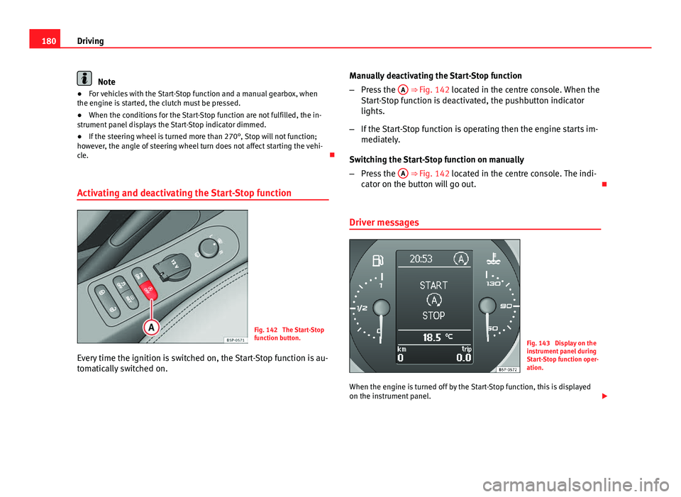
Activating and deactivating the Start-Stop function
Fig. 142 The Start-Stop
function button.
Every time the ignition is switched on, the Start-Stop function is au-
tomatically switched on. Manually deactivating the Start-Stop function
–
Press the A
⇒ Fig. 142 located in the centre console. When the
Start-Stop function is deactivated, the pushbutton indicator
lights.
– If the Start-Stop function is operating then the engine starts im-
mediately.
Switching the Start-Stop function on manually
– Press the A
⇒ Fig. 142 located in the centre console. The indi-
cator on the button will go out.
Driver messages
Fig. 143 Display on the
instrument panel during
Start-Stop function oper-
ation.
When the engine is turned off by the Start-Stop function, this is displayed
on the instrument panel.
Page 317 of 321
Remote control keyButtons . . . . . . . . . . . . . . . . . . . . . . . . . . . . 104
Synchronising . . . . . . . . . . . . . . . . . . . . . . . 105
Removing and fitting the wheel . . . . . . . . . . . 268
Repairs Airbags . . . . . . . . . . . . . . . . . . . . . . . . . . . . . 32
Replacement keys . . . . . . . . . . . . . . . . . . . . . . 102
Replacement of parts . . . . . . . . . . . . . . . . . . . . 226
Rev counter . . . . . . . . . . . . . . . . . . . . . . . . . . . . . 59
Reverse gear Manual gearbox . . . . . . . . . . . . . . . . . . . . . 182
Roll-back function Sliding/tilting sunroof . . . . . . . . . . . . . . . . 114
Windows . . . . . . . . . . . . . . . . . . . . . . . . . . . 111
Roof aerial . . . . . . . . . . . . . . . . . . . . . . . . . . . . . 227
Roof rack . . . . . . . . . . . . . . . . . . . . . . . . . . . . . . 158
Roof storage compartment . . . . . . . . . . . . . . . 143
Rubber seals . . . . . . . . . . . . . . . . . . . . . . . . . . . 218
Run-flat tyres . . . . . . . . . . . . . . . . . . . . . . . . . . 257
Running in Engine . . . . . . . . . . . . . . . . . . . . . . . . . . . . . 204
S Safe- security system . . . . . . . . . . . . . . . . . . . . . 97
Safe driving . . . . . . . . . . . . . . . . . . . . . . . . . . . . . 7
Safety . . . . . . . . . . . . . . . . . . . . . . . . . . . . . . . . . . 8
Safety equipment . . . . . . . . . . . . . . . . . . . . . . . . . 7
Safety instructions Coolant temperature . . . . . . . . . . . . . . . . . . 81 Safety notes
Airbags . . . . . . . . . . . . . . . . . . . . . . . . . . . . . 32
Curtain airbags . . . . . . . . . . . . . . . . . . . . . . . 42
Deactivating front passenger airbag . . . . . . 45
Front airbags . . . . . . . . . . . . . . . . . . . . . . . . 37
Seat belt tensioners . . . . . . . . . . . . . . . . . . . 29
Side airbags . . . . . . . . . . . . . . . . . . . . . . . . . 39
Using child seats . . . . . . . . . . . . . . . . . . . . . 46
Using seat belts . . . . . . . . . . . . . . . . . . . . . . 23
Seals . . . . . . . . . . . . . . . . . . . . . . . . . . . . . . . . . 218
Seat adjustment . . . . . . . . . . . . . . . 134, 137, 139
Seat belt cleaning . . . . . . . . . . . . . . . . . . . . . . 225
Seat belt control lamp . . . . . . . . . . . . . . . . . . . . 19
Seat belt position Pregnant women . . . . . . . . . . . . . . . . . . . . . 27
Seat belts . . . . . . . . . . . . . . . . . . . . . . . . . . . 26
Seat belt protection . . . . . . . . . . . . . . . . . . . . . . 23
Seat belt release . . . . . . . . . . . . . . . . . . . . . . . . 27
Seat belts . . . . . . . . . . . . . . . . . . . . . . . . . . . . . . 19 Adjustment . . . . . . . . . . . . . . . . . . . . . . . . . . 25
control lamp . . . . . . . . . . . . . . . . . . . . . . . . . 19
Incorrectly fastened . . . . . . . . . . . . . . . . . . . 28
Not worn . . . . . . . . . . . . . . . . . . . . . . . . . . . . 22
Safety notes . . . . . . . . . . . . . . . . . . . . . . . . . 23
Seat belt tensioner control lamp . . . . . . . . . . . . . . . . . . . . . . . . . 32
Seat belt tensioners . . . . . . . . . . . . . . . . . . . . . . 29
Seat heating . . . . . . . . . . . . . . . . . . . . . . . . . . . 138
Seat upholstery Alcantara . . . . . . . . . . . . . . . . . . . . . . . . . . . 222
Checklist . . . . . . . . . . . . . . . . . . . . . . . . . . . 221
cleaning Alcantara . . . . . . . . . . . . . . . . . . . 222 Cleaning and maintenance of natural leath-
er . . . . . . . . . . . . . . . . . . . . . . . . . . . . . . . 223
cleaning the trim fabric . . . . . . . . . . . . . . . 222
synthetic leather . . . . . . . . . . . . . . . . . . . . 224
Selective opening . . . . . . . . . . . . . . . . . . . . . . . 97
Selector lever locking . . . . . . . . . . . . . . . . . . . . 184
Selector lever positions . . . . . . . . . . . . . . . . . . 183
servotronic . . . . . . . . . . . . . . . . . . . . . . . . . . . . 202
Side airbags . . . . . . . . . . . . . . . . . . . . . . . . . . . . 37 Description . . . . . . . . . . . . . . . . . . . . . . . . . . 37
Operation . . . . . . . . . . . . . . . . . . . . . . . . . . . 39
Safety notes . . . . . . . . . . . . . . . . . . . . . . . . . 39
Side lights . . . . . . . . . . . . . . . . . . . . . . . . . . . . . 115
Sitting position driver . . . . . . . . . . . . . . . . . . . . . . . . . . . . . . . 10
Sitting position, occupants . . . . . . . . . . . . . . . . 10
Sliding/tilting sunroof . . . . . . . . . . . . . . . . . . . 112
Snow chains . . . . . . . . . . . . . . . . . . . . . . . 260, 296
Soot accumulation in the diesel engine particu- late filter *
Indicator . . . . . . . . . . . . . . . . . . . . . . . . . . . . 82
Spare parts . . . . . . . . . . . . . . . . . . . . . . . . . . . . 226
Spare wheel . . . . . . . . . . . . . . . . . . . . . . . . . . . 262
Start-Stop Activating and deactivating . . . . . . . . . . . . 180
Function . . . . . . . . . . . . . . . . . . . . . . . . . . . 179
Starting petrol engines . . . . . . . . . . . . . . 174, 175
Starting the engine . . . . . . . . . . . . . . . . . 174, 175 After the fuel tank has been run dry . . . . . 175
Steam jets . . . . . . . . . . . . . . . . . . . . . . . . . . . . . 216
Steering . . . . . . . . . . . . . . . . . . . . . . . . . . . . . . 171 Steering lock . . . . . . . . . . . . . . . . . . . . . . . . 173
315
Index