ECO mode Seat Ateca 2016 Owner's Manual
[x] Cancel search | Manufacturer: SEAT, Model Year: 2016, Model line: Ateca, Model: Seat Ateca 2016Pages: 328, PDF Size: 6.32 MB
Page 6 of 328
Table of Contents
Adaptive Cruise Control ACC* . . . . . . . . . . . . . . 197
Front Assist system including City emergency
br ak
ing and pedestrian monitoring* . . . . . . . . 207
Lane Assist system* . . . . . . . . . . . . . . . . . . . . . . 213
Traffic Jam Assist . . . . . . . . . . . . . . . . . . . . . . . . 216
Emergency Assist . . . . . . . . . . . . . . . . . . . . . . . . 218
Blind spot detector (BSD) with parking assis-
tanc
e (RCTA)* . . . . . . . . . . . . . . . . . . . . . . . . . . . 220
SEAT Drive Profile* . . . . . . . . . . . . . . . . . . . . . . . 225
Traffic sign detection system* . . . . . . . . . . . . . . 228
Fatigue detection (break recommendation)* . . 231
Park Assist* . . . . . . . . . . . . . . . . . . . . . . . . . . . . 232
Parking System Plus (ParkPilot)* . . . . . . . . . . . 239
Parking aid (ParkPilot)* . . . . . . . . . . . . . . . . . . . 244
Area View* . . . . . . . . . . . . . . . . . . . . . . . . . . . . . 247
Rear Assist (Rear View Camera)* . . . . . . . . . . . . 252
Towing bracket device* . . . . . . . . . . . . . . . . . . . 255
Trailer mode . . . . . . . . . . . . . . . . . . . . . . . . . . . . 255
Advice . . . . . . . . . . . . . . . . . . . . . . . . . . . . . . . . 265
Care and maintenance . . . . . . . . . . . . . . . . . . . . 265
Accessories and modifications to the vehi-
cl
e . . . . . . . . . . . . . . . . . . . . . . . . . . . . . . . . . . . . 265
Care and cleaning . . . . . . . . . . . . . . . . . . . . . . . 266
Vehicle exterior care . . . . . . . . . . . . . . . . . . . . . . 266
Caring for the vehicle interior . . . . . . . . . . . . . . 270
Intelligent technology . . . . . . . . . . . . . . . . . . . . 273
Electromechanical steering . . . . . . . . . . . . . . . . 273
Four-wheel drive . . . . . . . . . . . . . . . . . . . . . . . . . 273
Power Management . . . . . . . . . . . . . . . . . . . . . . 274
Checking and refilling levels . . . . . . . . . . . . . . . 276
Filling the tank . . . . . . . . . . . . . . . . . . . . . . . . . . 276
Fuel . . . . . . . . . . . . . . . . . . . . . . . . . . . . . . . . . . . 277
Exhaust purification system for vehicles with
diesel
engines (AdBlue ®
) . . . . . . . . . . . . . . . . . 279
Engine compartment . . . . . . . . . . . . . . . . . . . . . 282
Engine oil . . . . . . . . . . . . . . . . . . . . . . . . . . . . . . 284
Cooling system . . . . . . . . . . . . . . . . . . . . . . . . . . 286 Brake fluid . . . . . . . . . . . . . . . . . . . . . . . . . . . . . 287
Windscreen washer reservoir . . . . . . . . . . . . . . 288
Battery . . . . . . . . . . . . . . . . . . . . . . . . . . . . . . . . . 289
Wheels
. . . . . . . . . . . . . . . . . . . . . . . . . . . . . . . . 291
Wheels and tyres . . . . . . . . . . . . . . . . . . . . . . . . 291
Tyre monitoring systems . . . . . . . . . . . . . . . . . . 295
Temporary spare wheel . . . . . . . . . . . . . . . . . . . 298
Winter service . . . . . . . . . . . . . . . . . . . . . . . . . . . 299
Technical data . . . . . . . . . . . . . . . . . . . . . . . . 301
Technical specifications . . . . . . . . . . . . . . . . . . 301
Important . . . . . . . . . . . . . . . . . . . . . . . . . . . . . . 301
Vehicle identification data . . . . . . . . . . . . . . . . . 301
Information on fuel consumption . . . . . . . . . . . 302
Trailer mode . . . . . . . . . . . . . . . . . . . . . . . . . . . . 303
Wheels . . . . . . . . . . . . . . . . . . . . . . . . . . . . . . . . 303
Engine data . . . . . . . . . . . . . . . . . . . . . . . . . . . . . 304
Dimensions . . . . . . . . . . . . . . . . . . . . . . . . . . . . . 307
Index . . . . . . . . . . . . . . . . . . . . . . . . . . . . . . . . . 309
4
Page 33 of 328
The essentialsMenuFunction
Audio
Station display on the radio.
Track name on the CD.
Track name in Media mode
››› Booklet Ra-
dio or ››› Booklet Navigation system.
Tele-
phoneInformation and possible configurations
of the mobile phone preinstallation
››› Booklet Radio or ››› Booklet Navigation
system.
Vehicle
statusDisplay of the current warning or informa-
tion texts and other system components,
depending on the equipment
››› page 108. Outside temperature display
When the outside temperature is below +4°C
(+39°F), the “ic
e c
rystal” symbol (warning of
risk of freezing) is also displayed. At first, this
symbol flashes and then it remains lit until
the outside temperature rises above +6°C
(+43°F) ››› in Indications on the display on
p ag
e 105.
When the vehicle is at a standstill or when
travelling at very low speeds, the tempera-
ture displayed may be higher than the true
outside temperature as a result of the heat
produced by the engine.
The temperatures measured range from
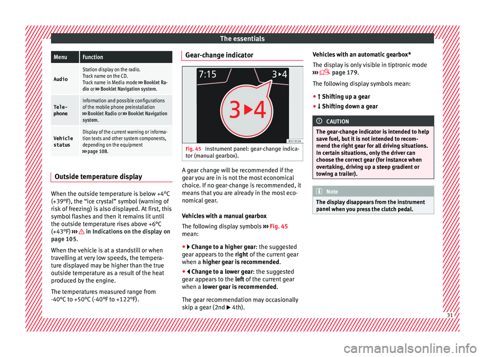
-40°C to +50°C (-40°F to +122°F). Gear-change indicator
Fig. 45
Instrument panel: gear-change indica-
t or (m
anual gearbox). A gear change will be recommended if the
g
e
ar you are in is not the most economical
choice. If no gear-change is recommended, it
means that you are already in the most eco-
nomical gear.
Vehicles with a manual gearbox
The following display symbols ››› Fig. 45
mean:
● Ch an
ge to a higher gear: the suggested
gear appears to the right of the current gear
when a higher gear is recommended .
● Chan
ge to a lower gear: the suggested
gear appears to the left of the current gear
when a lower gear is recommended .
The gear recommendation may occasionally
skip a gear (2nd 4th). Vehicles with an automatic gearbox*
The di
s
play is only visible in tiptronic mode
››› page 179.
The following display symbols mean:
● Shif tin
g up a gear
● Shiftin
g down a gear CAUTION
The gear-change indicator is intended to help
s av
e fuel, but it is not intended to recom-
mend the right gear for all driving situations.
In certain situations, only the driver can
choose the correct gear (for instance when
overtaking, driving up a steep gradient or
towing a trailer). Note
The display disappears from the instrument
p anel
when you press the clutch pedal. 31
Page 35 of 328
The essentials
Driving data M emor
y The MFD (multifunction display) shows differ-
ent
values for the journey and the consump-
tion.
Changing between display modes on the
MFD
● In vehicles without multifunction steering
whee
l: Press the rocker switch on the
w ind
screen wiper lever ›››
Fig. 42.
● Vehicles with a multifunction steering
whe e
l: turn the thumbwheel ›››
Fig. 43.
Multifunction display memory
The multifunction display is equipped with
three memories that work automatically: MFD
from departure, MFD from refuelling and MFD
total calculation. On the screen display, you
can read which memory is currently dis-
played.
● Toggle between memories with the ignition
on and the memory
displayed: Press the
button on the windscreen wiper lever
or the button of the multifunction steering
wheel .
MenuFunction
MFD from
departure
Display and storage of the values for
the journey and the consumption from
when the ignition is switched on to
when it is switched off.
If the journey is continued in less than
2 hours after the ignition is switched
off, the new data is added to the data
already stored in the memory. The
memory will automatically be deleted if
the journey is interrupted for more than
2 hours.
MFD from refuellingDisplay and storage of the values for
the journey and the consumption. By
refuelling, the memory will be erased
automatically.
MFD total
calcula-
tion
The memory records the values for a
specific number of partial trips, up to a
total of 19 hours and 59 minutes or 99
hours and 59 minutes, or 1999.9 km or
9999 km, depending on the model of
instrument panel. On reaching either of
these limits a)
, the memory is automati-
cally erased and starts to count from 0
again.
a) It varies according to the instrument panel version.
Erasing a memory manually
● Select the memory that you wish to erase.
● Hold the button of the multifunction
s t
eering wheel or the button of the multi-
f u
nction wheel pressed down for about 2 sec-
onds. Personalising the displays
In the Ea
sy Connect system you can adjust
which of the possible displays of the MFD can
be shown on the instrument panel display
with the button and the function button
Set up
› ››
p
age 108.
Data summary
MenuFunction
Current fuel
consumption
The current fuel consumption dis-
play operates throughout the jour-
ney, in litres/100 km; and with the
engine running and the vehicle
stopped, in litres/hour.
Average fuel consumption
After turning on the ignition, aver-
age fuel consumption in li-
tres/100 km will be displayed after
travelling about 100 metres. Other-
wise horizontal lines are displayed.
The value shown is updated approxi-
mately every 5 seconds.
ACT ®
*: Depending on the equip-
ment, number of active cylinders.
Operating range
Approximate distance in km that can
still be travelled with the fuel re-
maining in the tank, assuming the
same style of driving is maintained.
This is calculated using the current
fuel consumption.
Travelling timeThis indicates the hours (h) and mi-
nutes (min) since the ignition was
switched on.
» 33
Page 38 of 328
The essentials
the display mode changes. A clock symbol
ap pe
ars and the number of days until the
next service is due.
Vehicles with text messages : Service in
--- km or --- days will be shown on the
instrument panel display.
Service due
When the service date is due , an audible
warning is given when the ignition is switch-
ed on and the spanner displayed on the
screen flashes for a few seconds .
Vehicles with text messages : Service now
will be shown on the instrument panel dis-
play.
Reading a service notification
With the ignition switched on, the engine off
and the vehicle at a standstill, the current
service notification can be read:
Press and hold the button ›››
Fig. 115
4 for more than 5 seconds to consult the serv-
ic
e me
ssage.
When the service date has passed , a minus
sign is displayed in front of the number of kil-
ometres or days.
Vehicles with text messages : the following
message is displayed: Service --- km
(miles) or --- days ago .The time can also be set via the
key and
Set up function button in the Easy Connect
sy s
tem ›››
page 108.
Resetting service interval display
If the service was not carried out by a SEAT
dealership, the display can be reset as fol-
lows: ● Switch off the ignition, press and hold but-
ton ›
›› Fig. 115
4 .
● Switch ignition back on.
● Release THE 4
› ›
›
Fig. 115 button and
press it again for the next 20 seconds. Note
● The ser v
ice message disappears after a few
seconds, when the engine is started or when OK/RESET is pressed on the windscreen wiper
l ev
er, or OK on the multifunction steering
wheel .
● In
vehicles with the LongLife system in
which the b
attery has been disconnected for
a long period of time, it is not possible to cal-
culate the date of the next service. Therefore
the service interval display may not be cor- rect. In this case, bear in mind the maximum
service intervals permitted in the ››› Book-
let Maintenance Programme.
● If you reset the display manually, the next
serv
ice interval will be indicated as in vehi-
cles with fixed service intervals. For this rea-
son we recommend that the service interval
display be reset by a SEAT authorised Dealer. Cruise control
Oper atin
g the cruise control system
(CCS)* Fig. 47
On the left of the steering column:
sw it
ches and controls for operating the CCS Fig. 48
On the left of the steering column:
thir d l
ever to operate the CCS. 36
Page 70 of 328
Safety
Seat belts
Wh y
wear a seat belt?
Number of seats Your vehicle has
five
seats, two in the front
and three in the rear. Each seat is equipped
with a three-point seat belt.
In some versions, your vehicle is approved
only for four seats. Two front seats and two
rear seats. WARNING
● Nev er tr
ansport more than the permitted
amount of people in your vehicle.
● Every vehicle occupant must properly fas-
ten and w
ear the seat belt belonging to his or
her seat. Children must be protected with an
appropriate child restraint system. Seat belt lamp*
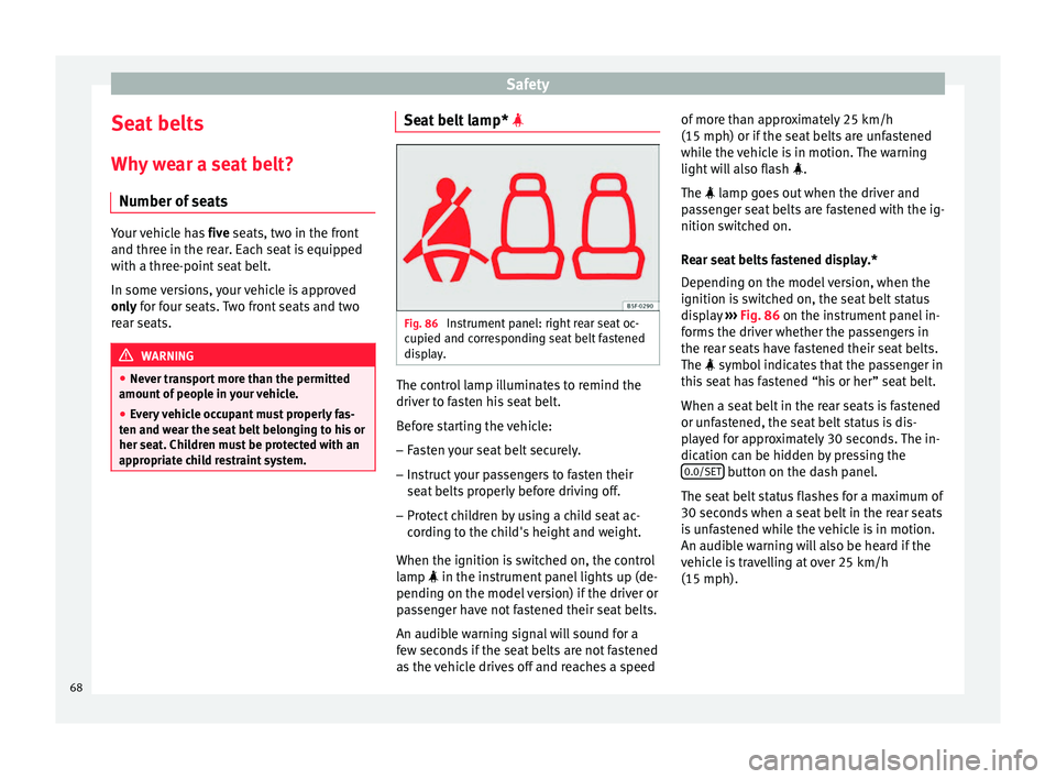
Fig. 86
Instrument panel: right rear seat oc-
c upied and c
orresponding seat belt fastened
display. The control lamp illuminates to remind the
driv
er t
o fasten his seat belt.
Before starting the vehicle: – Fasten your seat belt securely.
– Instruct your passengers to fasten their
seat
belts properly before driving off.
– Protect children by using a child seat ac-
cor
ding to the child's height and weight.
When the ignition is switched on, the control
lamp in the instrument panel lights up (de-
pending on the model version) if the driver or
passenger have not fastened their seat belts.
An audible warning signal will sound for a
few seconds if the seat belts are not fastened
as the vehicle drives off and reaches a speed of more than approximately 25 km/h
(15 mph) or if the se
at belts are unfastened
while the vehicle is in motion. The warning
light will also flash .
The lamp goes out when the driver and
passenger seat belts are fastened with the ig-
nition switched on.
Rear seat belts fastened display.*
Depending on the model version, when the
ignition is switched on, the seat belt status
display ››› Fig. 86 on the instrument panel in-
forms the driver whether the passengers in
the rear seats have fastened their seat belts.
The symbol indicates that the passenger in
this seat has fastened “his or her” seat belt.
When a seat belt in the rear seats is fastened
or unfastened, the seat belt status is dis-
played for approximately 30 seconds. The in-
dication can be hidden by pressing the 0.0/SET button on the dash panel.
The se at
belt status flashes for a maximum of
30 seconds when a seat belt in the rear seats
is unfastened while the vehicle is in motion.
An audible warning will also be heard if the
vehicle is travelling at over 25 km/h
(15 mph).
68
Page 83 of 328
Transporting children safely
WARNING
When travelling, children must be secured in
the v
ehicle with a restraint system suitable
for age, weight and size.
● Read and always observe information and
warnin
gs concerning the use of child seats
››› page 79. WARNING
The retaining rings are designed only for use
w ith “ISOFIX” and T
op Tether* system child
seats.
● Never secure other child seats that do not
hav
e the “ISOFIX” or Top Tether* system, or
retaining belts or objects to the fastening
rings - this can result in potentially fatal inju-
ries to the child.
● Ensure that the child seat is secured cor-
rectly
using the “ISOFIX” and Top Tether* se-
curing rings. WARNING
An undue installation of the safety seat will
inc r
ease the risk of injury in the event of a
crash.
● Never tie the retainer strap to a hook in the
lugg
age compartment.
● Never secure or tie luggage or other items
to the lo
wer anchorages (ISOFIX) or the upper
ones (Top Tether). Categorisation of child seats into
gr
oup
s Use only child seats that are officially ap-
pr
o
ved and suitable for the child.
These seats are subject to the ECE-R 44 or
ECE-R 129 standard. ECE-R stands for: Eco-
nomic Commission for Europe Regulation.
The child seats are grouped into 5 catego-
ries:
Group 0: Up to 10 kg (up to around 9
months)
Group 0+: Up to 13 kg (up to around 18
months)
Group 1: from 9 to 18 kg (up to approx. 4
years old)
Group 2: from 15 to 25 kg (up to approx. 7
years old)
Group 3: From 22 to 36 kg (over around 7
years old)
Child seats that have been tested and ap-
proved under the ECE-R 44 or ECE-R 129
standard bear the test mark ECE-R 44 or ECE-
R 129 on the seat (the letter E in a circle with
the test number below it).
Follow the manufacturer's instructions and
observe any statutory requirements when in-
stalling and using child seats. We recommend you to always include the
m
anuf
acturer's Child Seat Instruction Manual
together with the on-board documentation.
SEAT recommends you use child seats from
the Original Accessories Catalogue . These
child seats have been designed and tested
for use in SEAT vehicles. You can find the
right child seat for your model and age group
at SEAT dealers.
Child seats by approval category
Child seats may have the approval category
of universal, semi-universal, vehicle specific
(all according to the ECE-R 44 standard) or i-
Size (according to the ECE-R 129 standard).
● Universal: Chil
d seats with universal appro-
val can be installed in all vehicles. There is
no need to consult any list of models. In the
case of universal approval for ISOFIX, the
child seat is additionally provided with a Top
Tether belt.
● Semi-universal: semi-univ
ersal approval, in
addition to the standard requirements of uni-
versal approval, requires safety devices to
lock the child seat, which require additional
testing. Child seats with semi-universal ap-
proval include a list of vehicle models for
which they can be installed.
● Vehicle-specific: v
ehicle-specific approval
requires a dynamic test of the child seat for
each vehicle model separately. Child seats
with vehicle-specific approval also include a »
81
Technical data
Advice
Operation
Emergencies
Safety
Page 84 of 328
Safety
list of vehicle models for which they can be
in s
talled.
● i-Size: Child seats with i-Size approval must
meet
the requirements prescribed in the ECE-
R 129 standard in relation to installation and
safety. Child seat manufacturers can tell you
which seats have i-Size approval for this vehi-
cle.
Attachment systems Depending on the country, different attach-
ment
sy
stems are used for safely installing
child seats.
Attachment systems overview
● ISOFIX: ISOFIX i
s a standardised attach-
ment system allowing quick and safe attach-
ment of child seats in the vehicle. ISOFIX at-
tachment establishes a rigid connection be-
tween the child seat and the car body.
The child seat has two rigid attachment clips,
called connectors. These connectors are fit-
ted into the ISOFIX attachment rings found
between the seat cushion and the backrest of
the vehicle's back seat (on the sides). ISOFIX
attachment systems are used mainly in Eu-
rope ›››
page 19. If necessary, ISOFIX at-
tachment may have to be supplemented with
a Top Tether belt or a support bracket. ●
Autom
atic three-point seat belt . Whenever
possible, it is preferable to attach the child
seats with the ISOFIX system rather than at-
taching them with an automatic three-point
seat belt ›››
page 18.
Additional attachment:
● Top Tether : The Top Tether belt is guided
o
ver the back of the rear seat and attached to
an anchor point with a hook. Anchor points
are located at the back of the rear seat back-
rest on the boot side ›››
page 22
. The
rings for retaining the Top Tether belt are
marked with an anchor symbol.
● Support bracket : Some c
hild seats rest on
the floor of the vehicle with a support brack-
et. The support bracket prevents the child
seat from tipping forward in the event of im-
pact. Child seats fitted with a support bracket
should only be used in the passenger seat
and side rear seats ››› . For the assembly of
thi s
type of seat you should also consult the
list of approved vehicles for this assembly,
available in the instructions for child restraint
systems.
Recommended systems for attaching child
seats
SEAT recommends attaching child seats as
follows: ●
Bab
y carriers or child seats in the opposite
direction of travel: ISOFIX and support brack-
et or iSize.
● Child seats in the direction of travel: ISO-
FIX and
Top Tether. WARNING
Incorrect use of the support bracket can
c au
se serious or fatal injury.
● Make sure the support bracket is correctly
and saf
ely installed.82
Page 106 of 328
Operation
● St ar
t-Stop system status display
››› page 188.
● Active cylinder management display
(ACT ®
)* ›
›› page 185
● Signs recognised by the traffic signal de-
tection sy
stem ››› page 228
● Low consumption driving status (ECO)
››
› page 104
● Identifying letters on engine (MKB).
Dis
tance travelled
The odometer registers the total distance
travelled by the car.
The odometer (trip ) shows the distance
travelled since the last odometer reset. The
last digit of the trip recorder indicates distan-
ces of 100 metres or one tenths of a mile.
● Briefly press the button ››
› Fig. 115 4 to re-
set the trip r
ecorder to 0.
● Keep the button 4 pressed for about 3
sec ond
s and the previous value will be dis-
played.
Time
● To set the time, keep the button ››
› Fig. 115
4 pressed for more than 3 seconds to select
the hour or minut e di
splay.
● To continue setting the time, press the up-
per or low
er part of the button 4 . Hold but-ton down to scroll through the numbers
quic
k
ly.
● Press the button 4 again in order to finish
settin g the time.
The time c
an also be set via the key and
Set up function button in the Easy Connect
sy s
tem ››› page 108.
Compass
With the ignition on and the navigation sys-
tem on, the cardinal point corresponding to
the direction of travel of the vehicle is dis-
played on the instrument panel.
Selector lever position
The selected gear is displayed on the side of
the selector lever and on the instrument pan-
el display. In positions D and S, and with the
Tiptronic, the corresponding gear is also dis-
played.
Recommended gear (manual gearbox)
The recommended gear in order to save fuel
is displayed on the instrument panel while
you are driving ›››
page 31.
Second speed display (mph or km/h)
In addition to the speedometer, the speed
can also be displayed in a different unit of
measurement (in miles or in km per hour). This option cannot be deactivated in models
des
tined for countries in which the second
speed must always be visible.
The second speed display can be adjusted in
the Easy Connect system via the key and
the Set
up function button
››
› page 108.
Speed warning
When the speed setting is exceeded, this will
be indicated on the instrument panel display.
This is very useful, for example when using
winter tyres that are not designed for driving
at the maximum speed of the vehicle
››› page 35.
The speed warning settings can be adjusted
in the Easy Connect system via the key
and the Set
up function button
››
› page 108.
Start-Stop operating display
Updated information relating to the status is
displayed on the instrument panel
››› page 188.
Low consumption driving status (ECO)*
Depending on the equipment, when driving,
the “ECO ” display appears on the instrument
panel when the vehicle is in low consump-
tion status due to active cylinder manage-
ment (ACT ®
)* ›››
page 185.
104
Page 141 of 328
Lights and visibility
Note
The light above the sun visor automatically
sw it
ches off after a few minutes in certain
conditions. This prevents the battery from
discharging. Windscreen wiper and window
w
iper sy
stems
Window wiper lever Read the additional information carefully
› ›
› page 25 CAUTION
If the ignition is switched off with the wind-
s c
reen wipers active, they complete their
wipe before returning to the rest position.
When switching the ignition back on, the
windscreen wiper will continue to operate at
the same wiping level. Ice, snow and other
obstacles on the windscreen may damage the
wiper and the windscreen wiper motor.
● If necessary, remove snow and ice from the
wind
screen wipers before starting your jour-
ney.
● Carefully lift the frozen windscreen wipers
from the gl
ass. SEAT recommends a de-icer
spray for this operation.
● Do not switch on the windscreen wipers if
the wind
screen is dry. Cleaning with the windscreen wipers while dry can cause dam-
ag
e.
● In icy
conditions, always check that the
wiper b
lades are not frozen to the glass be-
fore using the wipers. In cold weather, it may
help to leave the vehicle parked with the wip-
ers in service position ›››
page 60. Note
● The w ind
screen and window wipers only
function when the ignition is switched on and
the bonnet or rear lid, respectively, are
closed.
● The interval wipe speed varies according to
the v
ehicle speed. The faster the vehicle is
moving, the more often the windscreen is
cleaned.
● The rear wiper is automatically switched on
when the wind
screen wiper is on and the car
is in reverse gear. Windscreen wiper functions
Windscreen wiper performance in different sit-
uations
If the vehicle is at a
standstillThe activated position provision-
ally changes to the previous posi-
tion.
Windscreen wiper performance in different sit-
uations
During automatic
wipe
The air conditioner comes on for
approximately 30 seconds in air
recirculation mode to prevent the
smell of the windscreen washer
fluid entering the inside the vehi-
cle.
For the interval wipe
Intervals between wipes depend
on the vehicle's speed. The high-
er the vehicle speed the shorter
the intervals. Heated windscreen washer jets
The he
atin
g only thaws the frozen jets, it
does not thaw the water in the washer hoses.
When the ignition is switched on the heated
windscreen washer jets automatically adjust
the heat depending on the ambient tempera-
ture.
Headlight wash/wipe system
The headlight washers/wipers clean the
headlight lenses.
After the ignition is switched on, the first and
every fifth time the windscreen washer is
switched on, the headlights are also washed.
Therefore, the windscreen wiper lever should
be pulled towards the steering wheel when
the dipped beam or main beam are on. Any
incrusted dirt (such as insects) should be
cleaned regularly (e.g. when refuelling). »
139
Technical data
Advice
Operation
Emergencies
Safety
Page 159 of 328
Air conditioning
WARNING
Reduced visibility through the windows in-
c r
eases the risk of serious accidents.
● Always ensure that all windows are free of
ice and s
now, and that they are not fogged,
so as to maintain good visibility of everything
outside.
● The maximum heat output required to de-
fro
st windows as quickly as possible is only
available when the engine has reached its
normal running temperature. Only drive when
you have good visibility.
● Always ensure that you use the heating
sys
tem, fresh air system, air conditioner and
the heated rear window to maintain good visi-
bility to the outside.
● Never leave the air recirculation on for a
long period of
time. If the cooling system is
switched off and air recirculation mode
switched on, the windows can mist over very
quickly, considerably limiting visibility.
● Switch air recirculation mode off when it is
not r
equired. WARNING
Stuffy or used air will increase fatigue and re-
duc e driv
er concentration possibly resulting
in a serious accident.
● Never leave the fresh air fan turned off or
use the air r
ecirculation for long periods of
time; the air in the vehicle interior will not be
refreshed. CAUTION
● To r
eplace the pollen filter, always visit a
service centre.
● Switch the air conditioner off if you think it
ma
y be broken. This will avoid additional
damage. Have the air conditioner checked by
a specialised workshop.
● Repairs to the air conditioner require spe-
ci
alist knowledge and special tools. SEAT rec-
ommends visiting a SEAT Official Service. Note
● When the c oo
ling system is turned off, air
coming from the outside will not be dried. To
prevent fogging of the windows, SEAT recom-
mends leaving the cooling system (compres-
sor) turned on. To do this, press the button . The button lamp should light up.
● The maximum heat output required to de-
fr o
st windows as quickly as possible is only
available when the engine has reached its
normal running temperature.
● Keep the air intake slots in front of the
wind
screen free of snow, ice and leaves to en-
sure heating and cooling are not impaired,
and to prevent the windows from misting
over. Adjust using the Easy Connect sys-
t
em* 3 Ap
plies to vehicles with a Touch/Colour Media
S
ystem.
In the Easy Connect system it is also possible
to perform various adjustments to the Clima-
tronic.
Open the air conditioner menu
● Press the Setup button.
● OR: pr ess the MENU button in Easy Con-
nect .
With the rotating switch select the air
conditioner menu and open it.
On the touch screen you can see and change
the current settings, for example, the temper-
ature set for the driver and passenger sides,
the air distribution and the fan speed. With
button the driver and passenger side
t emper
atures are synchronised ›››
Book-
let Media System Touch/Colour, chapter Air
conditioning.
To switch a function on or off, or to select a
submenu, you must press the corresponding
function button.
For more information about functions
››› page 108. »
157
Technical data
Advice
Operation
Emergencies
Safety