display Seat Ateca 2018 Repair Manual
[x] Cancel search | Manufacturer: SEAT, Model Year: 2018, Model line: Ateca, Model: Seat Ateca 2018Pages: 348, PDF Size: 7.32 MB
Page 242 of 348
Operation
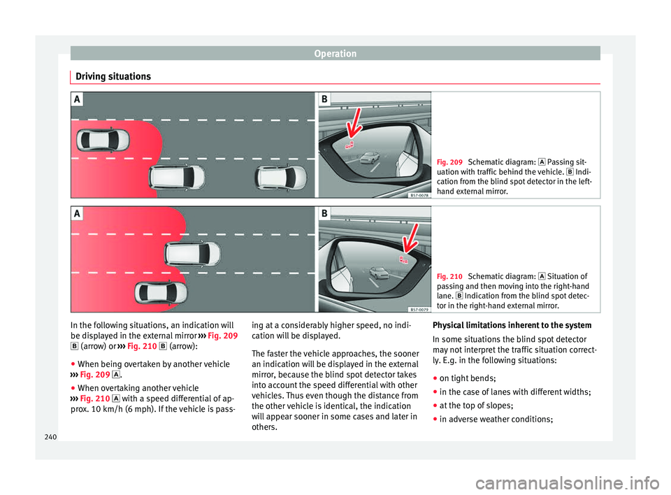
Driving situations Fig. 209
Schematic diagram: Pas sing sit-
uation with traffic behind the vehicle. Indi-
cation from the blind spot detector in the left-
hand external mirror. Fig. 210
Schematic diagram: Situation of
p a
ssing and then moving into the right-hand
lane. Indication from the blind spot detec- tor in the right-hand external mirror. In the following situations, an indication will
be di
s
p
layed in the external mirror ››› Fig. 209
(arrow) or ››› Fig. 210 (arrow):
● When being overtaken by another vehicle
›››
Fig. 209 .
● When overtaking another vehicle
›››
Fig. 210 with a speed differential of ap-
prox. 10 km/h (6 mph). If the vehicle is pass- ing at a considerably higher speed, no indi-
cation wi
ll be displayed.
The faster the vehicle approaches, the sooner
an indication will be displayed in the external
mirror, because the blind spot detector takes
into account the speed differential with other
vehicles. Thus even though the distance from
the other vehicle is identical, the indication
will appear sooner in some cases and later in
others. Physical limitations inherent to the system
In some situation
s the blind spot detector
may not interpret the traffic situation correct-
ly. E.g. in the following situations:
● on tight bends;
● in the case of lanes with different widths;
● at the top of slopes;
● in adverse weather conditions;
240
Page 243 of 348
Driver assistance systems
● in the c a
se of
special constructions to the
side of the vehicle, e.g., high or irregular di-
viders.
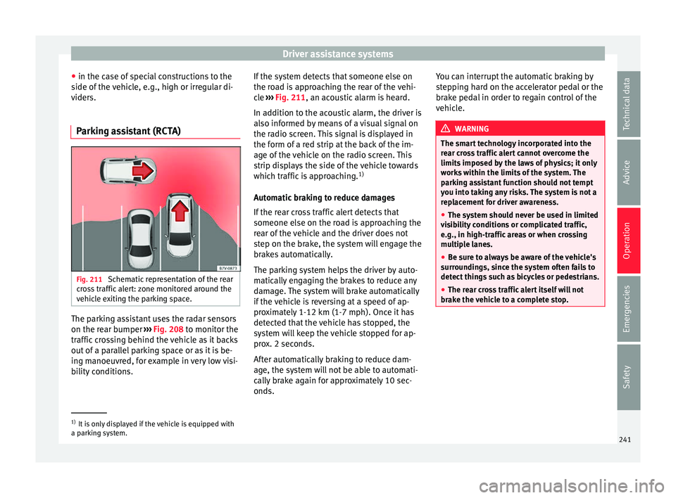
Parking assistant (RCTA) Fig. 211
Schematic representation of the rear
c r
o
ss traffic alert: zone monitored around the
vehicle exiting the parking space. The parking assistant uses the radar sensors
on the r
e
ar b
umper ››› Fig. 208 to monitor the
traffic crossing behind the vehicle as it backs
out of a parallel parking space or as it is be-
ing manoeuvred, for example in very low visi-
bility conditions. If the system detects that someone else on
the roa
d is approaching the rear of the vehi-
cle ››› Fig. 211, an acoustic alarm is heard.
In addition to the acoustic alarm, the driver is
also informed by means of a visual signal on
the radio screen. This signal is displayed in
the form of a red strip at the back of the im-
age of the vehicle on the radio screen. This
strip displays the side of the vehicle towards
which traffic is approaching. 1)
Automatic braking to reduce damages
If the rear cross traffic alert detects that
someone else on the road is approaching the
rear of the vehicle and the driver does not
step on the brake, the system will engage the
brakes automatically.
The parking system helps the driver by auto-
matically engaging the brakes to reduce any
damage. The system will brake automatically
if the vehicle is reversing at a speed of ap-
proximately 1-12 km (1-7 mph). Once it has
detected that the vehicle has stopped, the
system will keep the vehicle stopped for ap-
prox. 2 seconds.
After automatically braking to reduce dam-
age, the system will not be able to automati-
cally brake again for approximately 10 sec-
onds. You can interrupt the automatic braking by
step
ping hard on the accelerator pedal or the
brake pedal in order to regain control of the
vehicle. WARNING
The smart technology incorporated into the
re ar c
ross traffic alert cannot overcome the
limits imposed by the laws of physics; it only
works within the limits of the system. The
parking assistant function should not tempt
you into taking any risks. The system is not a
replacement for driver awareness.
● The system should never be used in limited
vis
ibility conditions or complicated traffic,
e.g., in high-traffic areas or when crossing
multiple lanes.
● Be sure to always be aware of the vehicle's
surrou
ndings, since the system often fails to
detect things such as bicycles or pedestrians.
● The rear cross traffic alert itself will not
brake the
vehicle to a complete stop. 1)
It is only displayed if the vehicle is equipped with
a park in
g system. 241
Technical data
Advice
Operation
Emergencies
Safety
Page 244 of 348
Operation
Using the blind spot detector (BSD)
w ith p
ark
ing assistant (RCTA)Activating and deactivating the blind spot
detect
or (BSD) w
ith parking assistant (RCTA)
The blind spot detector with parking assis-
tant can be switched on and off by accessing
the Assistance systems menu on the
dash panel display using the steering wheel
controls. If the vehicle is equipped with a
multifunction camera, it can also be ac-
cessed by means of the driver assistance sys-
tems key located on the main beam head-
light lever.
Open the Assistants menu.
● Blind spot
● Exit Assist
If
the verification box on the control panel is
checked , the functionality will be automat-
ically activated at ignition.
When the blind spot detector is ready to op-
erate, the indications in the external mirrors
will turn on briefly as confirmation.
When the vehicle is restarted, the last adjust-
ment in the system will remain active.
If the blind spot detector was automatically
deactivated, it will only be possible to restart
the system after turning the vehicle off and
restarting it. Automatic deactivation of the blind spot de-
tect
or (BSD)
The r
adar sensors of the blind spot detector
with rear cross traffic alert will be automati-
cally deactivated when, among other rea-
sons, one of the sensors is detected to be
permanently covered. This may be the case if,
for example, there is a layer of snow or ice in
front of one of the sensors.
The relevant text message will appear in the
dash panel display.
Trailer mode
The Blind spot detector and the rear cross
traffic alert will be automatically deactivated
and it will be impossible to activate them if
the tow hitch is electrically connected to a
trailer or other similar object.
As soon as the driver starts to drive with a
trailer connected electrically to the vehicle, a
message will appear on the instrument panel
display indicating that the blind spot detec-
tor and the rear cross traffic alert are deacti-
vated. Once the trailer has been unhitched
from the vehicle, if you want to use the blind
spot detector and the rear cross traffic alert,
you will have to reactivate them in the corre-
sponding menu.
If the towing hitch is not factory equipped,
then the blind spot detector and the rear
cross traffic alert will have to be deactivated
manually when driving with a trailer. SEAT Drive Profile*
Relat ed video Fig. 212
Autonomous
driving Introduction
The SEAT Drive Profile enables the driver to
c
hoo
se betw
een four profiles or modes, Eco,
Normal , Sport and Individual , that
modify the behaviour of various vehicle func-
tions, providing different driving experiences.
In addition, the 4Drive version features the Offroad and Snow profiles.
The Individual profile can be configured
according to personal preferences. The other
profiles have a fixed configuration.
Description Depending on the equipment fitted in the ve-
hic
l
e,
SEAT Drive Profile can operate on the
following functions:
242
Page 245 of 348
Driver assistance systems
Engine
D ependin
g on the pr
ofile selected, the en-
gine responds more spontaneously or more
in harmony with the movements of the accel-
erator. Additionally, when the Eco profile is
selected, the Start-Stop function is automati-
cally activated.
In vehicles with automatic transmission, the
gear change points are modified to position
them in lower or higher engine speed ranges.
Additionally, the Eco profile activates the in-
ertia function, enabling consumption to be
further reduced.
In manual gearbox vehicles, the Eco profile
causes the gear change recommendation in-
dications that appear on the dash panel to
vary, facilitating more efficient driving.
Address
The power steering varies its driving modes
and adapts to the profile selected, thus offer-
ing the best behaviour for each situation.
Air conditioning
In vehicles with Climatronic, this can operate
in Eco mode, especially restricting fuel con-
sumption. Adaptive cruise control (ACC)
The accel
eration gradient of the adaptive
cruise control varies according to the active
driving profile ››› page 221.
Electronic stability control (ESC)
In the Offroad and Snow driving profiles,
the electronic stability Control (ESC)
››› page 189 adjusts to adapt to the terrain.
In addition, hill descent control (HDC) is acti-
vated in the Offroad profile ››› page 210.
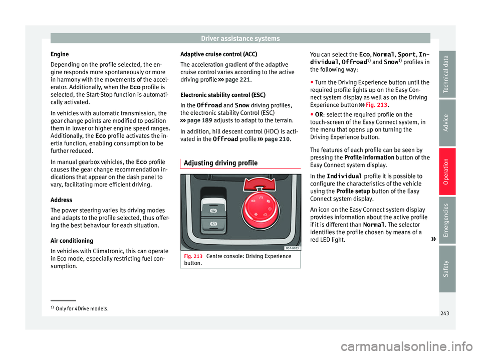
Adjusting driving profile Fig. 213
Centre console: Driving Experience
b utt
on. You can select the
Eco, Normal , Sport, In-
dividual , Offroad1)
and Snow 1)
pr ofi
l
es in
the following way:
● Turn the Driving Experience button until the
required pr
ofile lights up on the Easy Con-
nect system display as well as on the Driving
Experience button ››› Fig. 213.
● OR: select the required profile on the
touc
h-screen of the Easy Connect system, in
the menu that opens up on turning the
Driving Experience button.
The features of each profile can be seen by
pressing the Profile information button of the
Easy Connect system display.
In the Individual profile it is possible to
configure the characteristics of the vehicle
using the Profile setup button of the Easy
Connect system display.
An icon on the Easy Connect system display
provides information about the active profile
if it is different than Normal. The selector
identifies the profile chosen by means of a
red LED light. »1)
Only for 4Drive models.
243
Technical data
Advice
Operation
Emergencies
Safety
Page 247 of 348
Driver assistance systems
Traffic sign detection system* 1)
Intr oduction The traffic sign detection system records the
st
and
ard traffic signs in front of the vehicle
with a camera located on the base of the in-
terior mirror and provides information about
speed limits and overtaking prohibitions.
Within its limitations, the system also dis-
plays additional signals, such as time-specif-
ic prohibitions, signs for vehicles towing trail-
ers ›››
page 273 or limitations that only apply
in the event of rain. Even on journeys without
signs, the system may display any applicable
speed limits.
In Germany, on motorways and vehicle roads,
besides speed limits and overtaking provi-
sions the system also displays the end of
prohibition signs. The valid speed limit at the
time in other countries is always shown. WARNING
The technology in the traffic sign detection
sys t
em cannot change the limits imposed by
the laws of physics and only works within the
system's limits. Do not let the extra conven-
ience afforded by the traffic sign detection
system tempt you into taking any risks when
driving. The system is not a replacement for
driver awareness. ●
Adapt
your speed and driving style to suit
visibility, weather, road and traffic condi-
tions.
● Poor visibility, darkness, snow, rain and fog
may
lead to the system failing to display traf-
fic signs or not displaying them correctly.
● If the camera's field of vision is dirty, cov-
ered or dam
aged, system operation may be
impaired. WARNING
The driving recommendations and traffic indi-
c ation s
shown on the traffic sign detection
system may differ from the actual current
traffic situation.
● The system may not detect or correctly
show al
l the traffic signs.
● Traffic signs and traffic regulations have
priority ov
er the recommendations and dis-
plays provided by the system. Note
In order not to compromise the system's op-
eration, p l
ease take the following points into
account:
● Regularly clean the area of vision of the
camera and k
eep it in a clean state, without
snow or ice. ●
Do not c o
ver the field of vision of the cam-
era.
● Always replace damaged or worn blades
when required t
o avoid lines on the camera's
field of vision.
● Check that the windscreen is not damaged
in the area of
the camera's field of vision. Note
● The u se of out
dated maps on the naviga-
tion system may cause the system to show
traffic signs incorrectly.
● In the waypoints mode of the navigation
syst
em, the traffic sign detection system is
only partly available. 1)
System available depending on the country.
245
Technical data
Advice
Operation
Emergencies
Safety
Page 248 of 348
Operation
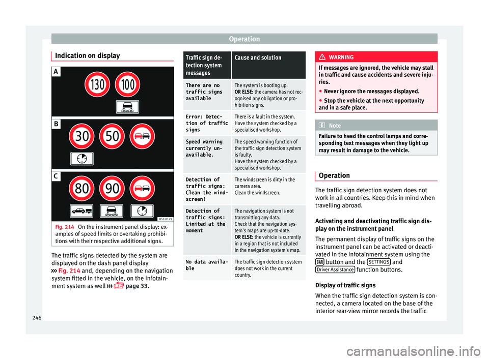
Indication on display Fig. 214
On the instrument panel display: ex-
amp l
e
s of speed limits or overtaking prohibi-
tions with their respective additional signs. The traffic signs detected by the system are
di
s
p
layed on the dash panel display
››› Fig. 214 and, depending on the navigation
system fitted in the vehicle, on the infotain-
ment system as well ›››
page 33.
Traffic sign de-
tection system
messagesCause and solution
There are no
traffic signs
availableThe system is booting up.
OR ELSE: the camera has not rec-
ognised any obligation or pro-
hibition signs.
Error: Detec- tion of traffic
signsThere is a fault in the system.
Have the system checked by a
specialised workshop.
Speed warningcurrently un-
available.The speed warning function of
the traffic sign detection system
is faulty.
Have the system checked by a
specialised workshop.
Detection oftraffic signs:
Clean the wind-
screen!The windscreen is dirty in the
camera area.
Clean the windscreen.
Detection of
traffic signs:
Limited at the
momentThe navigation system is not
transmitting any data.
Check that the navigation sys-
tem's maps are up-to-date.
OR ELSE: the vehicle is currently
in a region that is not included
in the navigation system's map.
No data availa- bleThe traffic sign detection system
does not work in the current
country. WARNING
If messages are ignored, the vehicle may stall
in traffic and c
ause accidents and severe inju-
ries.
● Never ignore the messages displayed.
● Stop the vehicle at the next opportunity
and in a safe p
lace. Note
Failure to heed the control lamps and corre-
spondin g t
ext messages when they light up
may result in damage to the vehicle. Operation
The traffic sign detection system does not
w
ork
in al
l countries. Keep this in mind when
travelling abroad.
Activating and deactivating traffic sign dis-
play on the instrument panel
The permanent display of traffic signs on the
instrument panel can be activated or deacti-
vated in the infotainment system using the button and the
S
ET
TINGS and
Driv er As
s
istance function buttons.
Di s
p
lay of traffic signs
When the traffic sign detection system is con-
nected, a camera located on the base of the
interior rear-view mirror records the traffic
246
Page 249 of 348
Driver assistance systems
signs in front of the vehicle. After checking
and ev aluatin
g the inf
ormation from the cam-
era, the navigation system and the current
vehicle data, up to three valid traffic signs
are displayed ››› Fig. 214 B in conjunction
with their corresponding additional signs.
The sign that is currently valid for the
driver is shown in the left side of the
screen For example, a maximum speed
limit of 130 km/h (100 mph)
››› Fig. 214 A.
A sign valid only in certain circum-
stances, e.g. 100 km/h (60 mph) is
shown second, together with the addi-
tional rain sign.
If the windscreen wiper is
working while you are driving, the signal
with the additional rain sign will be
shown first, on the left, as it is the one
that is applicable at the time.
A sign valid only with restrictions, e.g.
No overtaking at certain times, will be
displayed third ››› Fig. 214 C.
Speed warning
If the system detects that the permitted
speed is exceeded, it may warn the driver
with a “gong” and visually with a message
on the dash panel display.
The speed warning can be adjusted or deacti-
vated completely in the infotainment system
using the button and the
S
ET
TINGS and
First:
Second:
Additional sign:
Third:
Driver Assistance function buttons
› ›
›
page 33. The speed is adjusted in
steps of 5 km/h (3 mph) within a range of be-
tween 0 km/h (mph) and 20 km/h (12 mph)
above the maximum speed permitted.
Trailer mode
In vehicles equipped with a towing bracket
device from the factory and a trailer that is
electrically connected to the vehicle, it is pos-
sible to activate or deactivate the display of
specific traffic signs for vehicles with trailer,
such as speed limits or overtaking prohibi-
tions. Activation or deactivation is performed
on the infotainment system using the button and the
S
ET
TINGS and
Driv er As
s
istance function buttons
› ›
›
page 33.
For trailer mode, the display of speed limits
applicable to the type of trailer or to the legal
provisions can be adjusted. The speed is ad-
justed in steps of 10 km/h (5 mph) within a
range of between 60 km/h (40 mph) and
130 km/h (80 mph). If it is adjusted to a
speed greater than that which is permitted in
the country in question for driving with a
trailer, the system automatically displays the
usual speed limits, e.g. in Germany 80 km/h
(50 mph).
If the speed warning for the trailer is deacti-
vated, the system displays the speed limits
as if there were no trailer hitched. Limited operation
The traffic s
ign detection system has certain
limitations. The following cases may lead the
system to operate with limitations or not at
all:
● In the case of poor visibility, e.g. in snow,
rain, fog or int
ense mist.
● In cases of dazzling, e.g. caused by head-
on traffic or b
y the sun.
● When driving at high speeds.
● If the camera is covered or dirty.
● If the traffic signs are out of the camera's
field of
vision.
● If the traffic signs are partially or totally
cov
ered, e.g. by trees, snow, dirt or other ve-
hicles.
● In the case of traffic signs that do not fulfil
the regu
lations.
● In the case of damaged or bent traffic
signs.
● In the c
ase of variable messages on over-
head or g
antry signs (LED-based variable traf-
fic signs or other lighting units).
● If the maps on the navigation system are
not up-to-d
ate.
● In the case of adhesives affixed to vehicles
that depict
traffic signs, e.g. speed limits on
lorries.
247
Technical data
Advice
Operation
Emergencies
Safety
Page 250 of 348
Operation
Fatigue detection (break rec-
ommend ation)*
Intr oduction The Fatigue detection informs the driver
when their drivin
g beh
aviour shows signs of
fatigue. WARNING
Do not let the comfort afforded by the Fatigue
detection sy s
tem tempt you into taking any
risks when driving. Take regular breaks, suffi-
cient in length when making long journeys.
● The driver always assumes the responsibil-
ity of driv
ing to their full capacity.
● Never drive if you are tired.
● The system does not detect the tiredness of
the driver in al
l circumstances. Consult the in-
formation in the section ››› page 248, System
limitations.
● In some situations, the system may incor-
rectly int
erpret an intended driving manoeu-
vre as driver tiredness.
● No warning is given in the event of the ef-
fect c
alled microsleep!
● Please observe the indications on the in-
strument p
anel and act as is necessary. Note
● Fatigue det ection h
as been developed for
driving on motorways and well paved roads
only.
● If there is a fault in the system, have it
check
ed by a specialised workshop. Function and operation
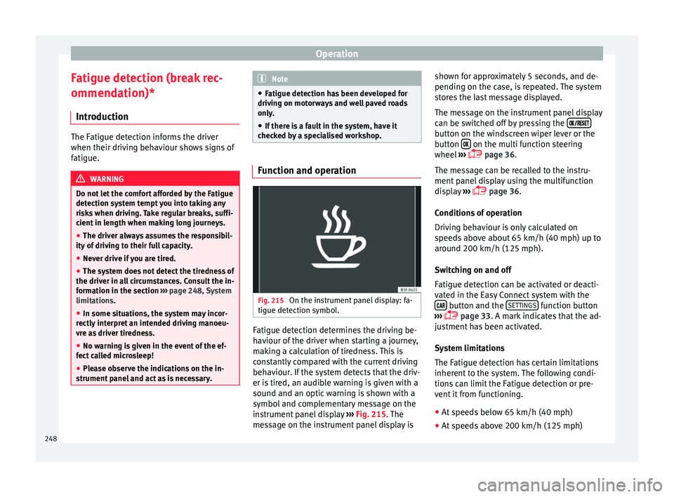
Fig. 215
On the instrument panel display: fa-
tigue det ection symbo
l
. Fatigue detection determines the driving be-
h
av
iour of
the driver when starting a journey,
making a calculation of tiredness. This is
constantly compared with the current driving
behaviour. If the system detects that the driv-
er is tired, an audible warning is given with a
sound and an optic warning is shown with a
symbol and complementary message on the
instrument panel display ››› Fig. 215. The
message on the instrument panel display is shown for approximately 5 seconds, and de-
pending on the ca
se, is repeated. The system
stores the last message displayed.
The message on the instrument panel display
can be switched off by pressing the button on the windscreen wiper lever or the
b
utt
on on the multi function steering
wheel
›
›
› page 36.
The message can be recalled to the instru-
ment panel display using the multifunction
display ›››
page 36.
Conditions of operation
Driving behaviour is only calculated on
speeds above about 65 km/h (40 mph) up to
around 200 km/h (125 mph).
Switching on and off
Fatigue detection can be activated or deacti-
vated in the Easy Connect system with the button and the
S
ET
TINGS function button
› ›
›
page 33. A mark indicates that the ad-
justment has been activated.
System limitations
The Fatigue detection has certain limitations
inherent to the system. The following condi-
tions can limit the Fatigue detection or pre-
vent it from functioning.
● At speeds below 65 km/h (40 mph)
● At speeds above 200 km/h (125 mph)
248
Page 252 of 348
Operation
CAUTION
● In cer t
ain circumstances, the ultrasonic
sensors do not detect objects such as trailer
tongues, bars, fences, posts or thin trees, or
an open (or opening) rear lid, which could
damage the vehicle.
● Retrofitting of certain accessories to the ve-
hicle, s
uch as a bicycle rack, may interfere
with the operation of the Park Assist system
and cause damage.
● The Park Assist system uses as a reference
parked
vehicles, curbs and other objects.
Make sure that the tyres and wheels are not
damaged while parking. If necessary, oppor-
tunely interrupt the parking manoeuvre to
avoid damaging the vehicle.
● The ultrasound sensors on the bumper may
be damag
ed or shifted in the event of a colli-
sion, for example, when entering or exiting a
parking space.
● If you use high-pressure or vapour equip-
ment to c
lean the ultrasound sensors, do not
apply it directly unless very briefly and al-
ways from a distance of more than 10 cm.
● A registration plate or plate holder on the
front w
ith larger than the space for the regis-
tration plate, or a registration plate that is
curved or warped can cause:
–false detections,
– loss of sensor visibility.
– cancellation of the parking manoeuvre or
defective parking. ●
If one of the u
ltrasonic sensors is damaged,
the area corresponding to that group of sen-
sors (front or rear) is deactivated and cannot
be activated until the fault is corrected. How-
ever, you can still use the sensors of the oth-
er bumper as per usual. If there is a fault in
the system, consult a specialist workshop.
SEAT recommends visiting a SEAT dealership
for this. Note
● In or der t o guar
antee good system opera-
tion, keep the ultrasound sensors of the
bumper clean, free of snow or ice, and do not
cover them with adhesives or other objects.
● Certain sources of noise, such as rough as-
phalt
or paving stones and the noise of other
vehicles can induce the Park Assist system or
ParkPilot to give erroneous warnings.
● In order to become familiar with the system
and its f
unctions, SEAT recommends that you
practice operating the Park Assist system in
an area where there is not too much traffic or
in a car park. Description of the Park Assist system
Fig. 217
At the top of the centre console: but-
t on t
o sw
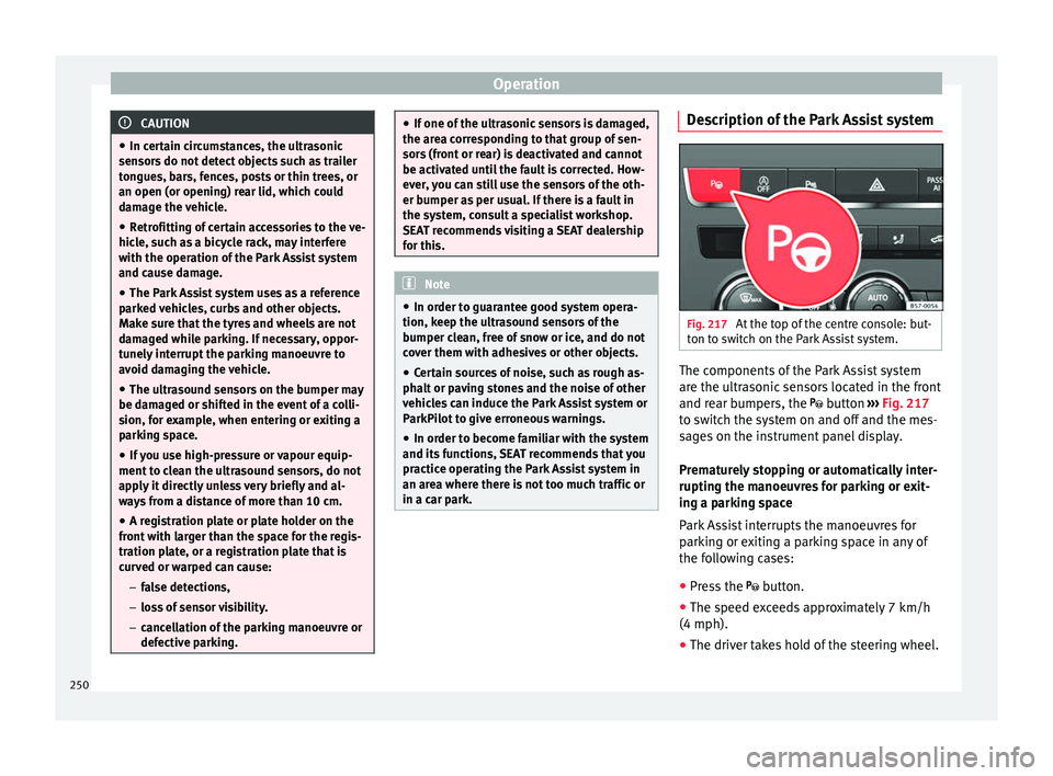
itch on the Park Assist system. The components of the Park Assist system
ar
e the u
ltr
asonic sensors located in the front
and rear bumpers, the button ›››
Fig. 217
to switch the system on and off and the mes-
sages on the instrument panel display.
Prematurely stopping or automatically inter-
rupting the manoeuvres for parking or exit-
ing a parking space
Park Assist interrupts the manoeuvres for
parking or exiting a parking space in any of
the following cases:
● Press the
button.
● The s
peed exceeds approximately 7 km/h
(4 mph).
● The driver takes hold of the steering wheel.
250
Page 253 of 348
Driver assistance systems
● The p ark
in
g manoeuvre does not end with-
in approximately 6 minutes following activa-
tion of the automatic steering.
● There is a fault in the system (the system is
temporari
ly unavailable).
● ASR is switched off.
● ASR or ESC intervene with regulation.
● The driver door is opened.
To re
start the manoeuvre it is necessary that
none of these things occur and that the
button is pressed again.
Special Characteristics
The Park Assist system is subject to certain
limitations inherent to the system. For exam-
ple, it is therefore not possible to enter or exit
a parking space on sharp bends. While entering or exiting a parking space, a
brief sign
al sounds to prompt the driver to
change between forward and reverse gears
(depending on the case). In successive ma-
noeuvres, the assistant tells the driver to
change gears, at the latest, when the contin-
uous audible signal is given (object present
at a distance of ≤30 cm) by Park Pilot.
When the Park Assist system turns the steer-
ing wheel with the vehicle stationary, the in-
strument panel also displays the symbol .
Keep the brake pedal depressed while the
symbol remains on the dash panel display to
turn the wheels with the vehicle stopped.
This way, the system will require fewer ma-
noeuvres to complete the parking action. Trailer mode
The Park As
sist system cannot be switched
on if the factory-fitted towing bracket
››› page 273 is electrically connected to a
trailer.
After changing a wheel
If, after changing a wheel, the vehicle stops
entering and exiting parking spaces correctly,
the circumference of the new wheel may be
different and the system may need to adapt
to it. The adaptation is automatic and takes
place during driving. Making turns slowly and
in both directions (20 km/h [12 mph]) for a
few minutes may contribute to this adapta-
tion process ››› in Introduction on
p ag
e 249
.
251
Technical data
Advice
Operation
Emergencies
Safety