Seat Cordoba 2006 Owner's Manual
Manufacturer: SEAT, Model Year: 2006, Model line: Cordoba, Model: Seat Cordoba 2006Pages: 255, PDF Size: 7.57 MB
Page 201 of 255
If and when199
Safety First
Operating instructions
Tips and Maintenance
Te c h n i c a l D a t a
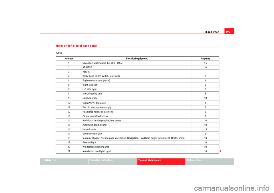
Fuses on left side of dash panelFuses
Number Electrical equipment Amperes
1 Secondary water pump 1.8 20 VT (T16) 15
2A BS/E S P 10
3 Vacant
4 Brake light, clutch switch, relay coils 5
5 Engine control unit (petrol) 5
6 Right side light 5
7 Left side light 5
8 Mirror heating unit 5
9 Lambda probe 10
10 Signal“S”
a). Radio unit 5
11 Electric mirror power supply 5
12 Headlamp height adjustment 5
13 Oil pressure/level sensor 5
14 Additional heating engine/fuel pump 10
15 Automatic gearbox unit 10
16 Heated seats 15
17 Engine control unit 5
18 Instrument panel /Heating and ventilation, Navigation, Headlamp height adjustment, Electric mirror 10
19 Reverse light 10
20 Windscreen washer pump 10
21 Main beam headlight, right 10
cordoba_ingles Seite 199 Freitag, 7. Oktober 2005 6:00 18
Page 202 of 255
If and when
200
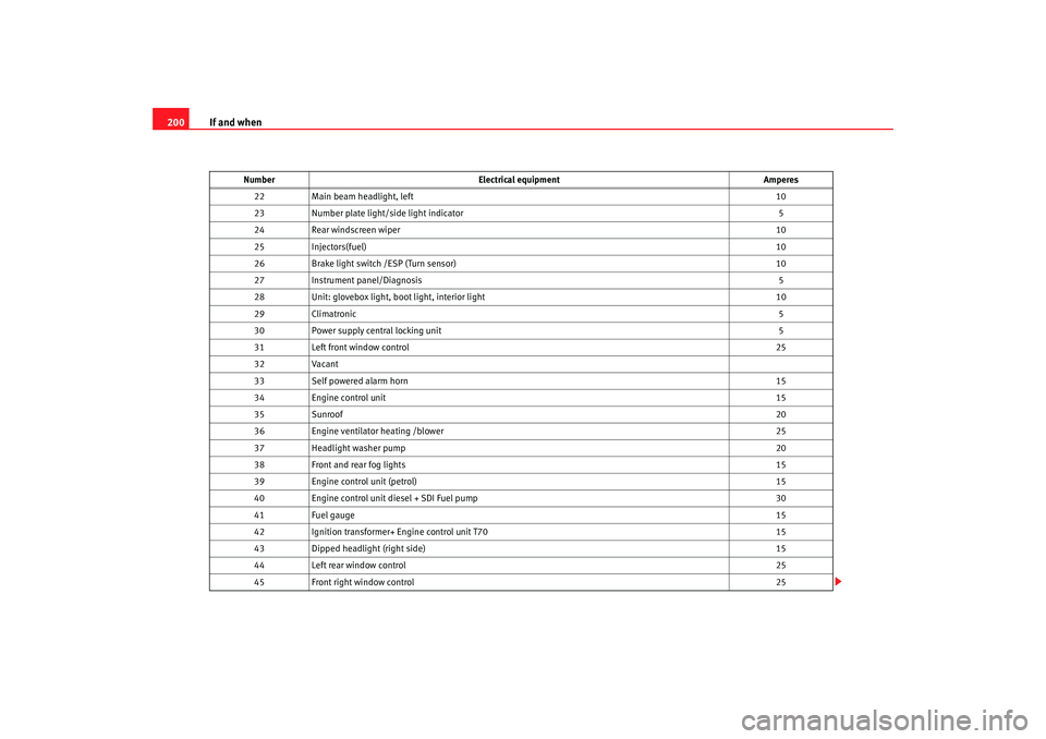
22 Main beam headlight, left 10
23 Number plate light/si de light indicator 5
24 Rear windscreen wiper 10
25 Injectors(fuel) 10
26 Brake light switch /ESP (Turn sensor) 10
27 Instrument panel/Diagnosis 5
28 Unit: glovebox light, boot light, interior light 10
29 Climatronic 5
30 Power supply central locking unit 5
31 Left front window control 25
32 Vacant
33 Self powered alarm horn 15
34 Engine control unit 15
35 Sunroof 20
36 Engine ventilator heating /blower 25
37 Headlight washer pump 20
38 Front and rear fog lights 15
39 Engine control unit (petrol) 15
40 Engine control unit diesel + SDI Fuel pump 30
41 Fuel gauge 15
42 Ignition transformer+ Engine control unit T70 15
43 Dipped headlight (right side) 15
44 Left rear window control 25
45 Front right window control 25
Number
Electrical equipment Amperes
cordoba_ingles Seite 200 Freitag, 7. Oktober 2005 6:00 18
Page 203 of 255
If and when201
Safety First
Operating instructions
Tips and Maintenance
Te c h n i c a l D a t a
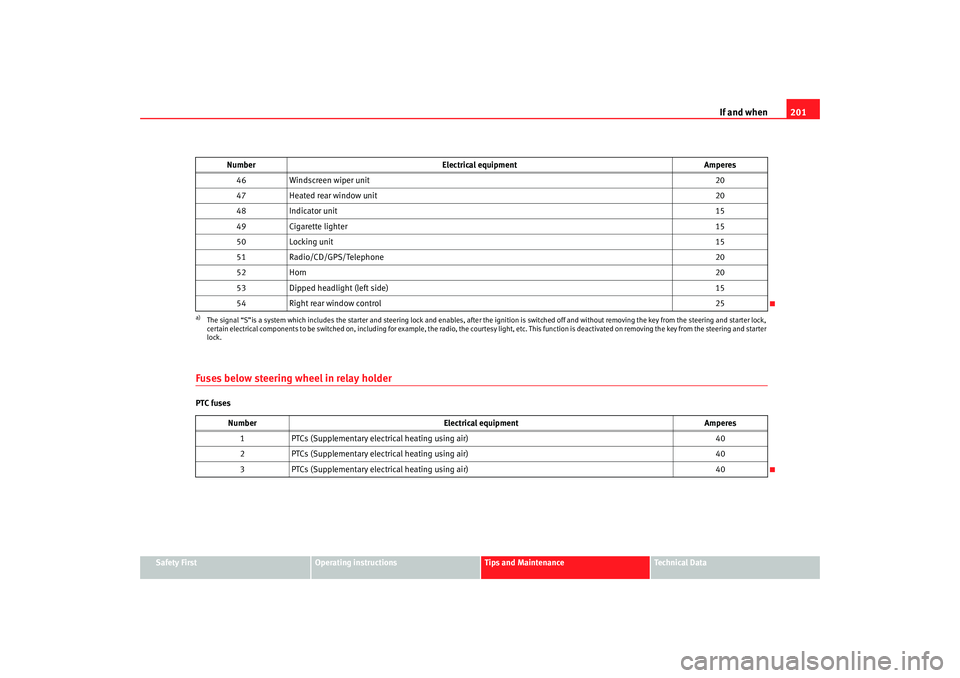
Fuses below steering wheel in relay holderPTC fuses 46
Windscreen wiper unit 20
47 Heated rear window unit 20
48 Indicator unit 15
49 Cigarette lighter 15
50 Locking unit 15
51 Radio/CD/GPS/Telephone 20
52 Horn 20
53 Dipped headlight (left side) 15
54 Right rear window control 25a)The signal “S”is a system which includes the starter and steering lock and enables, after the ignition is switched off and with out removing the key from the steering and starter lock,
certain electrical components to be switched on, including for example, the radio, the courtesy light, etc. This function is de activated on removing the key from the steering and starter
lock.
Number Electrical equipment Amperes
1 PTCs (Supplementary electrical heating using air) 40
2 PTCs (Supplementary electrical heating using air) 40
3 PTCs (Supplementary electrical heating using air) 40
Number
Electrical equipment Amperes
cordoba_ingles Seite 201 Freitag, 7. Oktober 2005 6:00 18
Page 204 of 255
If and when
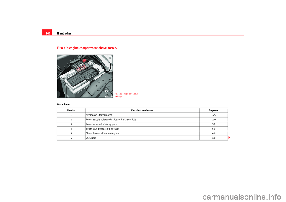
202Fuses in engine compartment above batteryMetal fuses
Fig. 137 Fuse box above
battery
Number Electrical equipment Amperes
1 Alternator/Starter motor 175
2 Power supply voltage distributor inside vehicle 110
3 Power assisted steering pump 50
4 Spark plug preheating (diesel) 50
5 Electroblower clima heater/fan 40
6 A BS u nit 40
cordoba_ingles Seite 202 Freitag, 7. Oktober 2005 6:00 18
Page 205 of 255
If and when203
Safety First
Operating instructions
Tips and Maintenance
Te c h n i c a l D a t a
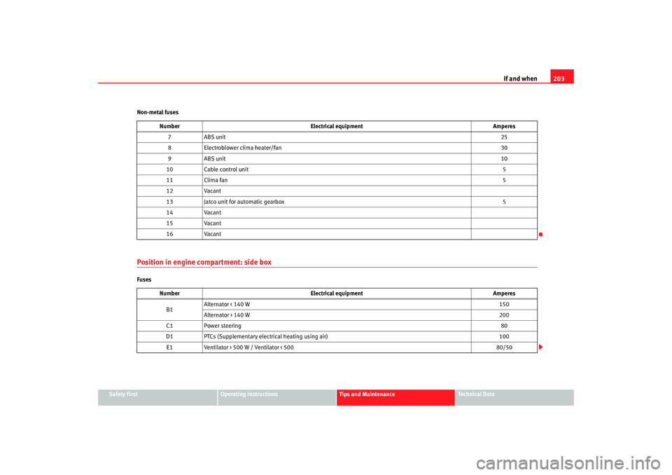
Non-metal fuses
Position in engine compartment: side boxFuses
Number
Electrical equipment Amperes
7A BS u nit 25
8 Electroblower clima heater/fan 30
9A BS u nit 10
10 Cable control unit 5
11 Clima fan 5
12 Vacant
13 Jatco unit for automatic gearbox 5
14 Vacant
15 Vacant
16 Vacant
Number Electrical equipment Amperes
B1 Alternator < 140 W
150
Alternator > 140 W 200
C1 Power steering 80
D1 PTCs (Supplementary electrical heating using air) 100
E1 Ventilator > 500 W / Ventilator < 500 80/50
cordoba_ingles Seite 203 Freitag, 7. Oktober 2005 6:00 18
Page 206 of 255
If and when
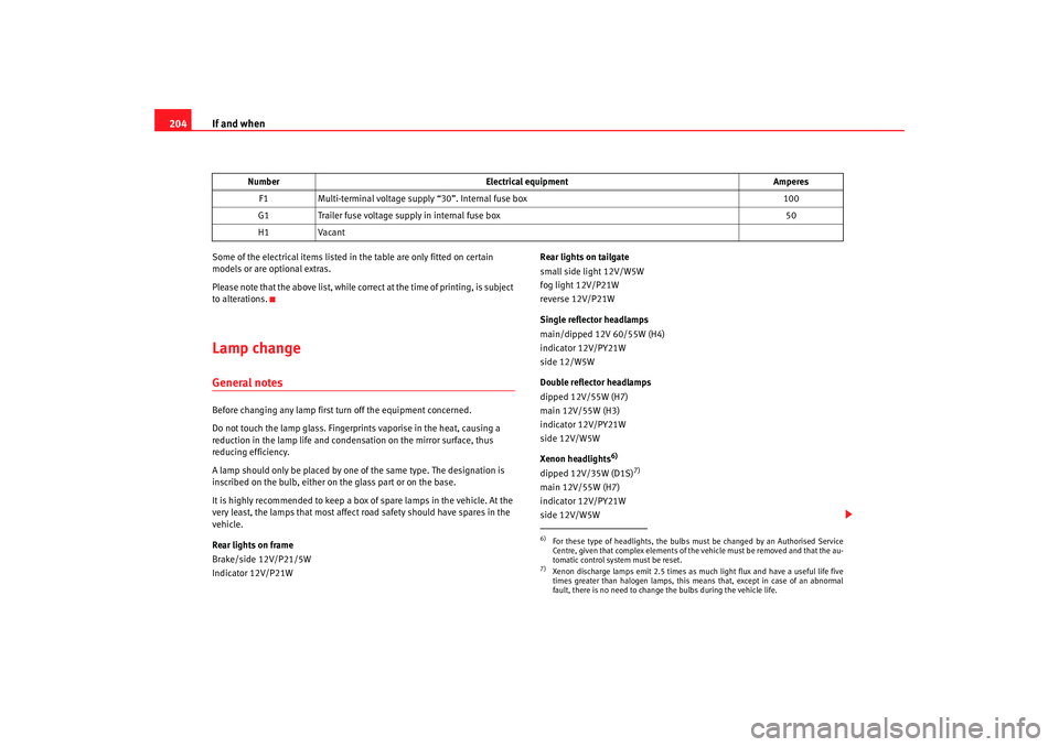
204Some of the electrical items listed in the table are only fitted on certain
models or are optional extras.
Please note that the above list, while corr ect at the time of printing, is subject
to alterations.Lamp changeGeneral notesBefore changing any lamp first turn off the equipment concerned.
Do not touch the lamp glass. Fingerprints vaporise in the heat, causing a
reduction in the lamp life and conden sation on the mirror surface, thus
reducing efficiency.
A lamp should only be placed by one of the same type. The designation is
inscribed on the bulb, either on the glass part or on the base.
It is highly recommended to keep a box of spare lamps in the vehicle. At the
very least, the lamps that most affect road safety should have spares in the
vehicle.
Rear lights on frame
Brake/side 12V/P21/5W
Indicator 12V/P21W Rear lights on tailgate
small side light 12V/W5W
fog light 12V/P21W
reverse 12V/P21W
Single reflector headlamps
main/dipped 12V 60/55W (H4)
indicator 12V/PY21W
side 12/W5W
Double reflector headlamps
dipped 12V/55W (H7)
main 12V/55W (H3)
indicator 12V/PY21W
side 12V/W5W
Xenon headlights
6)
dipped 12V/35W (D1S)
7)
main 12V/55W (H7)
indicator 12V/PY21W
side 12V/W5W
F1
Multi-terminal voltage supply “30”. Internal fuse box 100
G1 Trailer fuse voltage supply in internal fuse box 50
H1 Vacant
Number
Electrical equipment Amperes6)For these type of headlights, the bulbs must be changed by an Authorised Service
Centre, given that complex elements of the vehicle must be removed and that the au-
tomatic control system must be reset.7)Xenon discharge lamps emit 2.5 times as much light flux and have a useful life five
times greater than halogen lamps, this means that, except in case of an abnormal
fault, there is no need to change the bulbs during the vehicle life.
cordoba_ingles Seite 204 Freitag, 7. Oktober 2005 6:00 18
Page 207 of 255
If and when205
Safety First
Operating instructions
Tips and Maintenance
Te c h n i c a l D a t a
Fog lights*
Fog lights 12V/55W (H3)
Registration plate light
Registration plate light - C5W
Caution
•
The halogen lamps (H3, H7, H4...) are pressurised and might explode on
changing them.
•
Therefore protective gloves and glasses should be worn when changing a
halogen lamp.Note
•
Due to the difficulty in accessing the lamps, these must be changed by an
Authorised Service Centre. However, we shall explain how to change these
lamps, except for the xenon lights*.
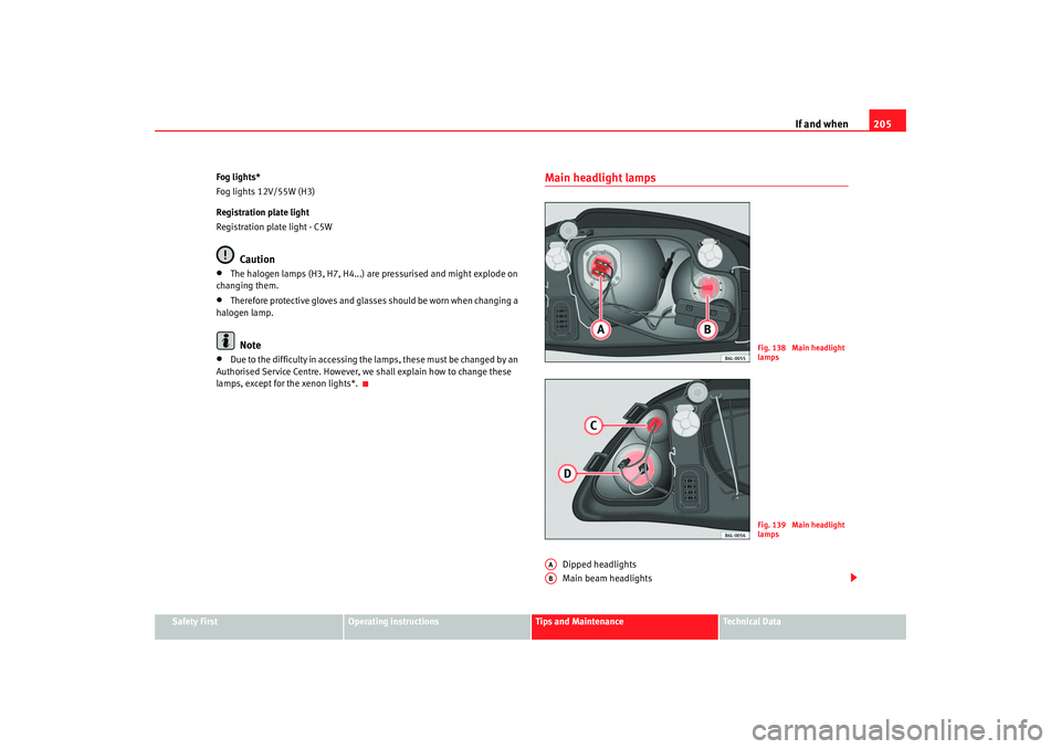
Main headlight lamps
Dipped headlights
Main beam headlights
Fig. 138 Main headlight
lampsFig. 139 Main headlight
lamps
AAAB
cordoba_ingles Seite 205 Freitag, 7. Oktober 2005 6:00 18
Page 208 of 255
If and when
206
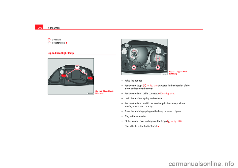
Side lights
Indicator lights
Dipped headlight lamp
–Raise the bonnet.
– Remove the loops ⇒fig. 140 outwards in the direction of the
arrow and remove the cover.
– Rem ove the lamp cable connector ⇒ fig. 141.
– Undo the retainer spring and remove.
– Remove the lamp and fit the new lamp in the same position, making sure it sits correctly.
– Press the retaining spring on the lamp base and clip on.
– Plug in the connector.
– Fit the plastic cover and replace the loops ⇒fig. 140.
– Check the headlight adjustment
ACAD
Fig. 140 Dipped head-
light lamp
Fig. 141 Dipped head-
light lamp
A2
AA
A2
cordoba_ingles Seite 206 Freitag, 7. Oktober 2005 6:00 18
Page 209 of 255
If and when207
Safety First
Operating instructions
Tips and Maintenance
Te c h n i c a l D a t a
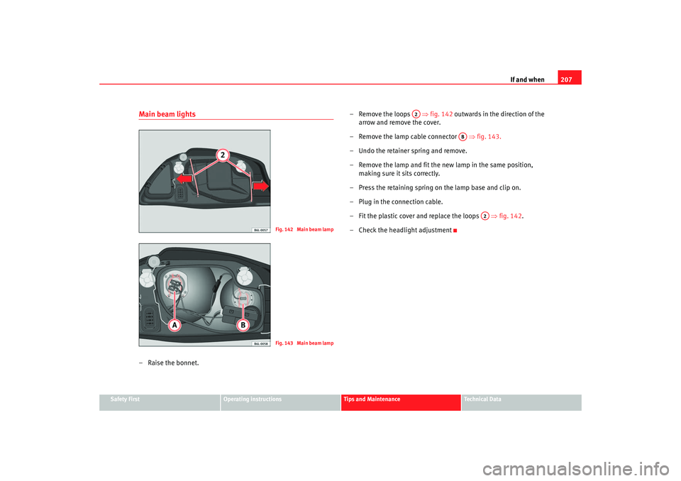
Main beam lights–Raise the bonnet. – Remove the loops
⇒fig. 142 outwards in the direction of the
arrow and remove the cover.
– Remove the lamp cable connector ⇒ fig. 143.
– Undo the retainer spring and remove.
– Remove the lamp and fit the new lamp in the same position, making sure it sits correctly.
– Press the retaining spring on the lamp base and clip on.
– Plug in the connection cable.
– Fit the plastic cover and replace the loops ⇒fig. 142.
– Check the headlight adjustment
Fig. 142 Main beam lampFig. 143 Main beam lamp
A2
AB
A2
cordoba_ingles Seite 207 Freitag, 7. Oktober 2005 6:00 18
Page 210 of 255
If and when
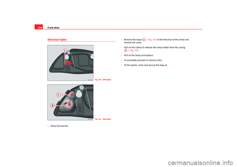
208Side beam lights– Raise the bonnet. – Remove the loops
⇒fig. 144 in the direction of the arrow and
remove the cover.
– Pull on the cables to release the lamp holder from the casing ⇒fig. 145.
–Pull on the lamp and replace.
– To assemble proceed in reverse order.
– Fit the plastic cover and secure the loop.
Fig. 144 Side lightsFig. 145 Side lights
A1
AC
cordoba_ingles Seite 208 Freitag, 7. Oktober 2005 6:00 18