clock Seat Cordoba 2006 Owner's Manual
[x] Cancel search | Manufacturer: SEAT, Model Year: 2006, Model line: Cordoba, Model: Seat Cordoba 2006Pages: 255, PDF Size: 7.57 MB
Page 12 of 255
Safe driving
10
– Always fasten your seat belt correctly ⇒page 17.
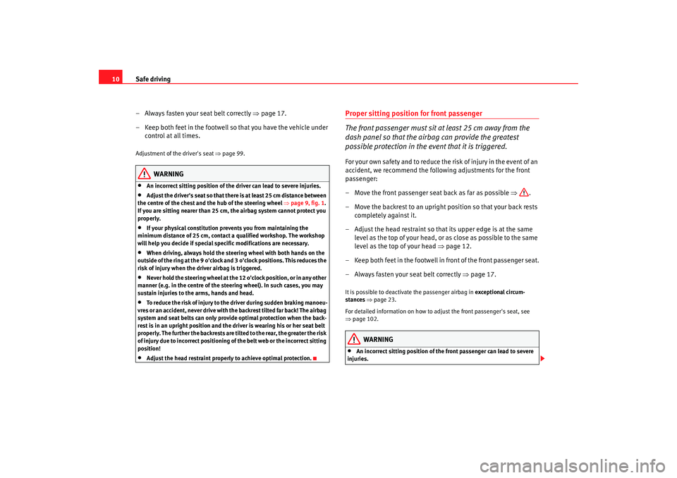
– Keep both feet in the footwell so that you have the vehicle under control at all times.Adjustment of the driver's seat ⇒page 99.
WARNING
•
An incorrect sitting position of the driver can lead to severe injuries.
•
Adjust the driver's seat so that the re is at least 25 cm distance between
the centre of the chest and the hub of the steering wheel ⇒page 9, fig. 1 .
If you are sitting nearer than 25 cm, the airbag system cannot protect you
properly.
•
If your physical constitution prevents you from maintaining the
minimum distance of 25 cm, contact a qualified workshop. The workshop
will help you decide if special specific modifications are necessary.
•
When driving, always hold the steer ing wheel with both hands on the
outside of the ring at the 9 o'clock and 3 o'clock positions. This reduces the
risk of injury when the driver airbag is triggered.
•
Never hold the steering wheel at the 12 o'clock position, or in any other
manner (e.g. in the centre of the stee ring wheel). In such cases, you may
sustain injuries to the arms, hands and head.
•
To reduce the risk of injury to the driver during sudden braking manoeu-
vres or an accident, never drive with the backrest tilted far back! The airbag
system and seat belts can only provide optimal protection when the back-
rest is in an upright position and the dr iver is wearing his or her seat belt
properly. The further the backrests are ti lted to the rear, the greater the risk
of injury due to incorrect positioning of the belt web or the incorrect sitting
position!
•
Adjust the head restraint properly to achieve optimal protection.
Proper sitting position for front passenger
The front passenger must sit at least 25 cm away from the
dash panel so that the airbag can provide the greatest
possible protection in the event that it is triggered.For your own safety and to reduce the risk of injur y in the event of an
accident, we recommend the following adjustments for the front
passenger:
– Move the front passenger seat back as far as possible ⇒.
– Move the backrest to an upright position so that your back rests completely against it.
– Adjust the head restraint so that its upper edge is at the same level as the top of your head, or as close as possible to the same
level as the top of your head ⇒page 12.
– Keep both feet in the footwell in front of the front passenger seat.
– Always fasten your seat belt correctly ⇒page 17.It is possible to deactivate the passenger airbag in exceptional circum-
stances ⇒page 23.
For detailed information on how to adjust the front passenger's seat, see
⇒ page 102.
WARNING
•
An incorrect sitting position of the front passenger can lead to severe
injuries.
cordoba_ingles Seite 10 Freitag, 7. Oktober 2005 6:00 18
Page 54 of 255
Cockpit
52InstrumentsInstrument overview
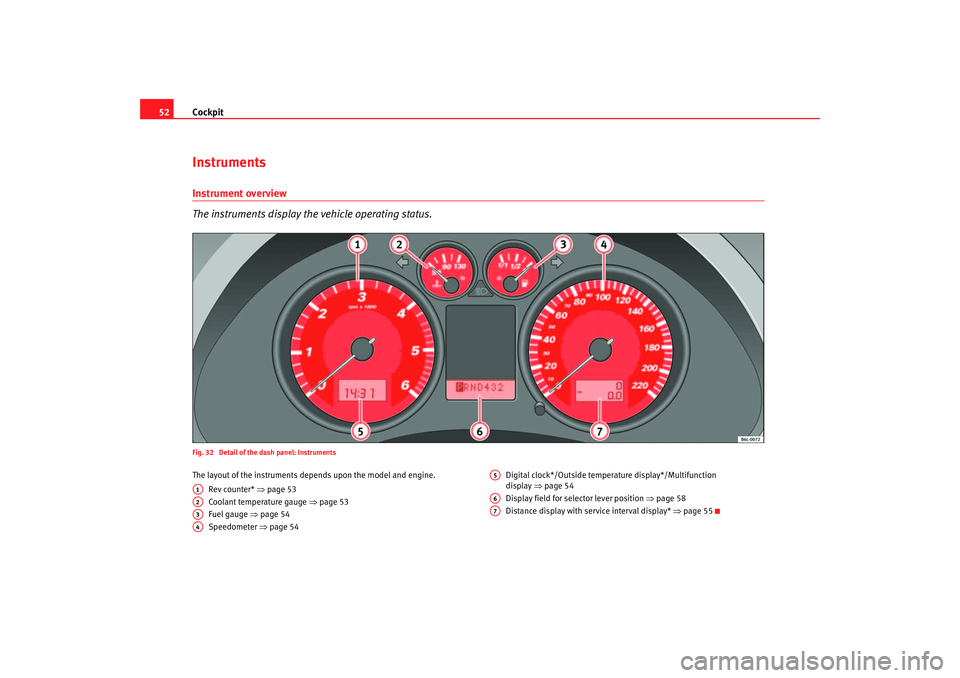
The instruments display the vehicle operating status.Fig. 32 Detail of the dash panel: InstrumentsThe layout of the instruments depends upon the model and engine.
Rev counter* ⇒ page 53
Coolant temperature gauge ⇒page 53
Fuel gauge ⇒ page 54
Speedometer ⇒page 54 Digital clock*/Outside temperature display*/Multifunction
d
ispla y ⇒ pa
ge 54
Display field for selector lever position ⇒page 58
Distance display with service interval display* ⇒page 55
A1A2A3A4
A5A6A7
cordoba_ingles Seite 52 Freitag, 7. Oktober 2005 6:00 18
Page 56 of 255
Cockpit
54
WARNING
When working in the engine compartment, always bear in mind the safety
wa rnings ⇒ page 169.
Caution
Accessories in front of the air inlet reduce the cooling effect of the coolant. At
high outside temperatures and high engine loads, there is a risk of the
engine overheating.Fuel gauge
and reserve indicator
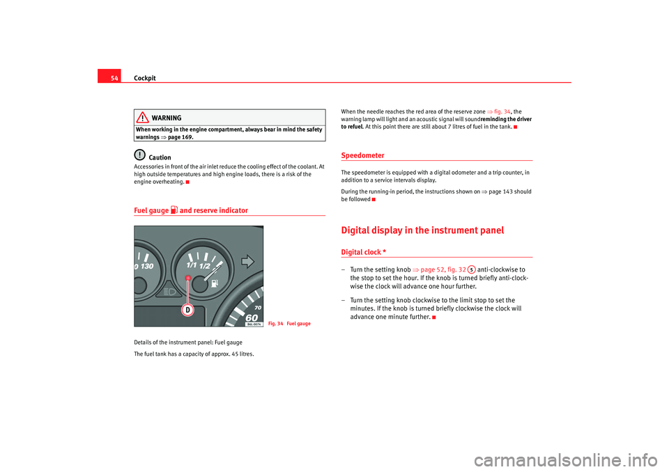
Details of the instrument panel: Fuel gauge
The fuel tank has a capacity of approx. 45 litres. When the needle reaches the red area of the reserve zone
⇒fig. 34 , the
warning lamp will light and an acoustic signal will sound reminding the driver
to refuel. At this point there are still about 7 litres of fuel in the tank.
SpeedometerThe speedometer is equipped with a digital odometer and a trip counter, in
addition to a service intervals display.
During the running-in period, the instructions shown on ⇒page 143 should
be followedDigital display in the instrument panelDigital clock *– Turn the setting knob ⇒page 52, fig. 32 anti-clockwise to
the stop to set the hour. If the kn ob is turned briefly anti-clock-
wise the clock will advance one hour further.
– Turn the setting knob clockwise to the limit stop to set the minutes. If the knob is turned briefly clockwise the clock will
advance one minute further.
Fig. 34 Fuel gauge
A5
cordoba_ingles Seite 54 Freitag, 7. Oktober 2005 6:00 18
Page 57 of 255
Cockpit55
Safety First
Operating instructions
Tips and Maintenance
Te c h n i c a l D a t a
Ambient temperature display*
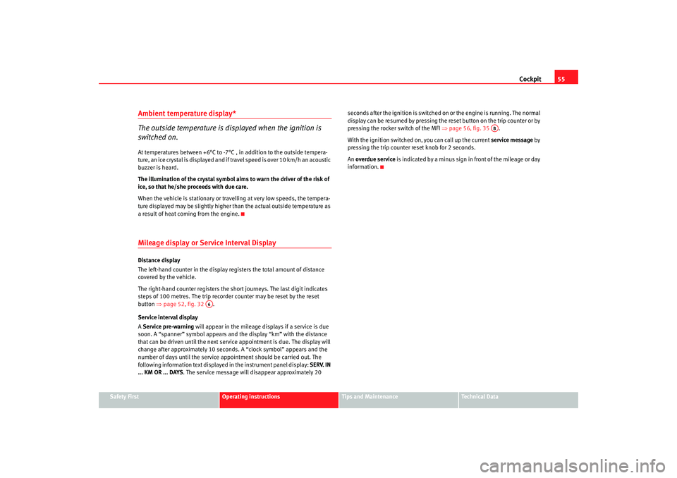
The outside temperature is displayed when the ignition is
switched on.At temperatures be t
ween +6°C to -7 °C
, in addition to the outside tempe ra-
ture, an ice crystal is displayed and if travel speed is over 10 km/h an acoustic
buzzer is heard.
The illumination of the crystal symbol ai ms to warn the driver of the risk of
ice, so that he/she proceeds with due care.
When the vehicle is stationary or travelling at very low speeds, the tempera-
ture displayed may be slightly higher than the actual outside temperature as
a result of heat coming from the engine.
Mileage display or Service Interval DisplayDistance display
The left-hand counter in the display registers the total amount of distance
covered by the vehicle.
The right-hand counter registers the sh ort journeys. The last digit indicates
steps of 100 metres. The trip recorder counter may be reset by the reset
button ⇒page 52, fig. 32 .
Service interval display
A Service pre-warning will appear in the mileage displays if a service is due
soon. A “spanner” symbol appears and the display “km” with the distance
that can be driven until the next service appointment is due. The display will
change after approximately 10 seconds. A “clock symbol” appears and the
number of days until the service appointment should be carried out. The
following information text displayed in the instrument panel display: SERV. IN
... KM OR ... DAYS . The service message will disappear approximately 20 seconds after the igni
tion is switched on or the engine is running. The normal
display can be resumed by pressing the reset button on the trip counter or by
pressing the rocker switch of the MFI ⇒page 56, fig. 35 .
With the ignition switched on, you can call up the current service message by
pressing the trip counter reset knob for 2 seconds.
An overdue service is indicated by a minus sign in front of the mileage or day
information.
A6
AB
cordoba_ingles Seite 55 Freitag, 7. Oktober 2005 6:00 18
Page 59 of 255

Cockpit57
Safety First
Operating instructions
Tips and Maintenance
Te c h n i c a l D a t a
Displays in the multi-function display (MFD)* You can switch between the following di splays in the multi-function display
(MFD) by operating the rocker switch ⇒ fig. 37 on the windscreen wiper
lever. Memory displays
•
Time
•
Journey duration
•
Average speed
•
Distance
•
Distance to empty (the distance you can travel with the remaining fuel)
•
Average fuel consumption
•
Current fuel consumption
Time
The time is also displayed when the ignition is switched off. The clock can be
set with the right-hand rotating button below the rev counter “digital clock”.
min - Journey duration
The display shows the amount of time which has elapsed since the ignition
was switched on.
The maximum display value in both memories is 99 hours and 59 minutes.
The memory will automatically be deleted once this value has been reached.
Ø mph - Average speed
The average speed will be shown after a distance of approximately 100
metres has been travelled. Dashes will appear in the display until that time.
The display will be updated every 5 seconds whilst the vehicle is in motion.
km - Distance travelled
The display shows the distance travelled since the ignition was switched on.
The maximum display value in both me mories is 9999 miles. The memory will
automatically be deleted once this value has been reached.
km - Fuel range
The fuel range is calculated using the fi gures for tank content and current fuel
consumption. It shows how far the vehicle can travel using the same condi-
tions as a reference.
Fig. 37 Windscreen wiper
and washer lever: Button
A and rocker switch BFig. 38 Digital screen on
the instrument panel:
outside temperature
display
AB
cordoba_ingles Seite 57 Freitag, 7. Oktober 2005 6:00 18
Page 76 of 255
Opening and closing
74Childproof locks
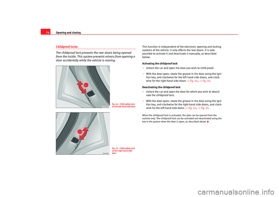
The childproof lock prevents the rear doors being opened
from the inside. This system prevents minors from opening a
door accidentally while the vehicle is moving.
This function is independent of the electronic opening and locking
systems of the vehicle. It only affects the rear doors. It is only
possible to activate it and deactivate it manually, as described
below:
Activating the childproof lock
– Unlock the car and open the door you wish to child-proof.
– With the door open, rotate the groove in the door using the igni-
tion key, anti-clockwise for the left hand side doors, and clock-
wise for the right hand side doors ⇒ fig. 44, ⇒ fig. 45.
Deactivating the childproof lock
– Unlock the car and open the door for which you wish to deacti- vate the childproof lock.
– With the door open, rotate the groove in the door using the igni- tion key, anti-clockwise for the right-hand side doors, and clock-
wise for the left-hand side door s ⇒ fig. 44, ⇒ fig. 45.When the childproof lock is activate d, the door can be opened from the
outside only. The childproof lock can be activated and deactivated using the
key in the groove when the door is open, as described above.
Fig. 44 Child safety lock
on the left hand side doorFig. 45 Child safety lock
on the right hand side
door
cordoba_ingles Seite 74 Freitag, 7. Oktober 2005 6:00 18
Page 115 of 255
Air conditioning113
Safety First
Operating instructions
Tips and Maintenance
Te c h n i c a l D a t a
•
In air recirculation mode, no air enters the vehicle interior from outside.
The windows can quickly fog over if the heating is switched off. Therefore,
you should never leave the air recirculation mode switched on for longer
periods, as this increases the risk of an accident.Note
•
Please observe the general notes ⇒page 120.
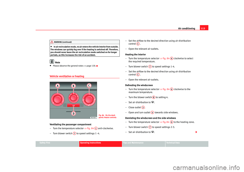
Vehicle ventilation or heatingVentilating the passenger compartment
– Turn the temperature selector ⇒ fig. 84 anti-clockwise.
– Turn blower switch to speed settings 1 -4. – Set the airflow to the desired direction using air distribution
control .
– Open the relevant air outlets.
Heating the interior
– Turn the temperature selector ⇒ fig. 84 clockwise to select
the required temperature.
– Turn blower switch to speed settings 1-4.
– Set the airflow to the desired direction using air distribution control .
– Open the relevant air outlets.
Defrosting the windscreen
– Turn the temperature selector ⇒ fig. 84 clockwise to the
maximum temperature.
– Turn the blower switch to setting 4.
– Set air distribution to
.
–Close outlet .
– Open and turn ou tlet towards side w indows.
De mi
sting the windscreen and the side windows
– Turn the temperature selector ⇒ fig. 84 to the heating zone.
– Turn blower swit ch to
speed settings 2-3.
– Set a
ir distribution to
.
WARNING (continued)
Fig. 84 On the dash
panel: Heater controls
A1
A7
AC
AA
A7
AC
AA
AB
A3
A4
AA
A7
cordoba_ingles Seite 113 Freitag, 7. Oktober 2005 6:00 18
Page 125 of 255
Driving123
Safety First
Operating instructions
Tips and Maintenance
Te c h n i c a l D a t a
•
Adjust the driver seat or steering wheel so that there is a distance of at
least 25 cm between the steering wheel and your breast bone ⇒page 122,
fig. 90 . If you fail to observe the minimum distance, the airbag will not
protect you. Risk of fatal injury.
•
If your physical constitution prevents you from maintaining the
minimum distance of 25 cm, contact an Authorised Service Centre. The
Authorised Service Centre will help you decide if special specific modifica-
tions are necessary.
•
If you adjust the steering wheel so th at it points towards your face, the
driver airbag will not protect you prop erly in the event of an accident. Make
sure that the steering wheel points towards your chest.
•
When driving, always hold the steering wheel with both hands on the
outside of the ring at the 9 o'clock and 3 o'clock positions. Never hold the
steering wheel at the 12 o'clock position, or in any other manner (e.g. in
the centre of the steering wheel, or on the inside of the rim). In such cases,
you could receive severe injuries to the arms, hands and head.
SafetyElectronic stabilisation programme (ESP)*
ESP helps make driving safer in certain situations.The Electronic Stabilisation Program (ESP ) contains the electronic differential
lock (EDL) and the traction control system (TCS). The ESP function works in
conjunction with the ABS. Both warning la mps will light up if the ESP or ABS
systems are faulty.
The ESP is started automatically when the engine is started.
In general, the ESP should always be on, but in specific circumstances where
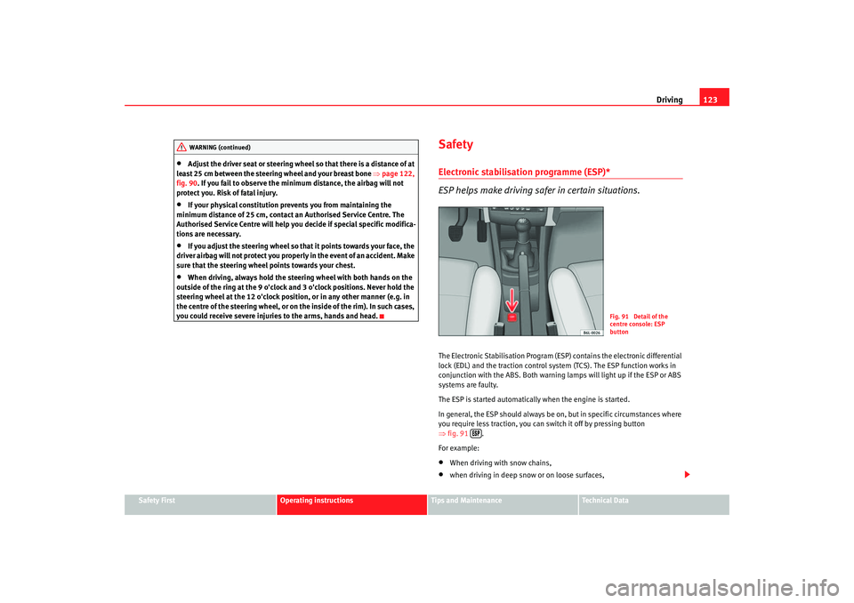
you require less traction, you can switch it off by pressing button
⇒ fig. 91 .
For example:•
When driving with snow chains,
•
when driving in deep snow or on loose surfaces,
WARNING (continued)
Fig. 91 Detail of the
centre console: ESP
button
cordoba_ingles Seite 123 Freitag, 7. Oktober 2005 6:00 18
Page 168 of 255
Checking and refilling levels
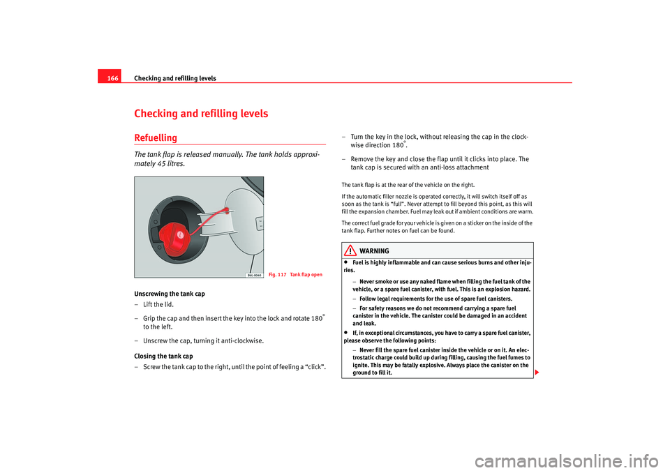
166Checking and refilling levelsRefuellingThe tank flap is released manually. The tank holds approxi-
mately 45 litres.Unscrewing the tank cap
–Lift the lid.
– Grip the cap and then insert the key into the lock and rotate 180
°
to the left.
– Unscrew the cap, turning it anti-clockwise.
Closing the tank cap
– Screw the tank cap to the right, until the point of feeling a “click”. – Turn the key in the lock, without releasing the cap in the clock-
wise direction 180
°.
– Remove the key and close the flap until it clicks into place. The tank cap is secured with an anti-loss attachment
The tank flap is at the rear of the vehicle on the right.
If the automatic filler nozzle is operated correctly, it will switch itself off as
soon as the tank is “full”. Never attempt to fill beyond this point, as this will
fill the expansion chamber. Fuel may leak out if ambient conditions are warm.
The correct fuel grade for your vehicle is given on a sticker on the inside of the
tank flap. Further notes on fuel can be found.
WARNING
•
Fuel is highly inflammable and can cause serious burns and other inju-
ries.
−Never smoke or use any naked flame when filling the fuel tank of the
vehicle, or a spare fuel canister, with fuel. This is an explosion hazard.
− Follow legal requirements for the use of spare fuel canisters.
− For safety reasons we do not recommend carrying a spare fuel
canister in the vehicle. The canister could be damaged in an accident
and leak.
•
If, in exceptional circumstances, you have to carry a spare fuel canister,
please observe the following points:
−Never fill the spare fuel canister inside the vehicle or on it. An elec-
trostatic charge could build up during filling, causing the fuel fumes to
ignite. This may be fatally explosive. Always place the canister on the
ground to fill it.
Fig. 117 Tank flap open
cordoba_ingles Seite 166 Freitag, 7. Oktober 2005 6:00 18
Page 248 of 255
Index
246CCar care
Exterior . . . . . . . . . . . . . . . . . . . . . . . . . . . . . 154
Car care products . . . . . . . . . . . . . . . . . . . . . . . 153
Car phone . . . . . . . . . . . . . . . . . . . . . . . . . . . . . 163
Car washes . . . . . . . . . . . . . . . . . . . . . . . . . . . . 154
Catalytic converter . . . . . . . . . . . . . . . . . . . . . . 144
Central locking . . . . . . . . . . . . . . . . . . . . . . . . . . 70 Automatic speed dependent locking and un-locking system* . . . . . . . . . . . . . . . . . . . . . 72
Emergency unlocking system . . . . . . . . . . . . 72
Locking system for invo luntary unlocking . . 72
Selective unlocking system* . . . . . . . . . . . . 71
Unlocking system* . . . . . . . . . . . . . . . . . . . . 72
Central locking button Central locking . . . . . . . . . . . . . . . . . . . . . . . 72
unlocking . . . . . . . . . . . . . . . . . . . . . . . . . . . . 72
Cetane number . . . . . . . . . . . . . . . . . . . . . . . . . 168
Change lamps dipped headlight lamp . . . . . . . . . . . . . . . . 206
Changing gear See Manual gearbox . . . . . . . . . . . . . . . . . . 128
Changing lamps interior light and reading light . . . . . . . . . . 213
changing lamps rearlights on frame . . . . . . . . . . . . . . . . . . . 212
rearlights on tailgate . . . . . . . . . . . . . . . . . 211
Changing the lamps glovebox light* . . . . . . . . . . . . . . . . . . . . . . 213
indicator lights . . . . . . . . . . . . . . . . . . . . . . 209 main beam lights . . . . . . . . . . . . . . . . . . . . 207
Main headlight lamps . . . . . . . . . . . . . . . . . 205
number plate light . . . . . . . . . . . . . . . . . . . 213
side beam lights . . . . . . . . . . . . . . . . . . . . . 208
Side indicator lights . . . .
. . . . . . . . . . . . . . 211
Changing windscreen wiper blades . . . . . . . . . 180
Chassis number . . . . . . . . . . . . . . . . . . . . . . . . 220
Checking . . . . . . . . . . . . . . . . . . . . . . . . . . . . . . 184
Checking battery electrolyte level . . . . . . . . . . 184
Checking engine oil level . . . . . . . . . . . . . . . . . 174
Child safety . . . . . . . . . . . . . . . . . . . . . . . . . . . . . 43
Child seat . . . . . . . . . . . . . . . . . . . . . . . . . . . . . . . 45 Categorisation in groups . . . . . . . . . . . . . . . 45
Group 1 . . . . . . . . . . . . . . . . . . . . . . . . . . . . . 46
Group 2 . . . . . . . . . . . . . . . . . . . . . . . . . . . . . 46
Group 3 . . . . . . . . . . . . . . . . . . . . . . . . . . . . . 46
Groups 0 and 0+ . . . . . . . . . . . . . . . . . . . . . . 45
ISOFIX system . . . . . . . . . . . . . . . . . . . . . . . . 48
Safety notes . . . . . . . . . . . . . . . . . . . . . . . . . . 44
Securing . . . . . . . . . . . . . . . . . . . . . . . . . . . . . 47
Child seats on the front passenger seat . . . . . . . . . . . . . 29
Cigarette lighter . . . . . . . . . . . . . . . . . . . . . . . . 108
Cleaning alloy wheels . . . . . . . . . . . . . . . . . . . . 158
Cleaning and caring for your vehicle . . . . . . . . 153
Cleaning chrome . . . . . . . . . . . . . . . . . . . . . . . . 157
Cleaning cloth seat covers . . . . . . . . . . . . . . . . 160
Cleaning dash panel . . . . . . . . . . . . . . . . . . . . . 159
Cleaning engine compartment . . . . . . . . . . . . . 159
Cleaning fabric trim . . . . . . . . . . . . . . . . . . . . . . 160 Cleaning leather . . . . . . . . . . . . . . . . . . . . . . . . 160
Cleaning plastic parts . . . . . . . . . . . . . . . . . . . . 159
Cleaning seat belts . . . . . . . . . . . . . . . . . . . . . . 161
Cleaning steel wheels . . . . . . . . . . . . . . . . . . . . 157
Cleaning windows . . . . . . . . . . . . . . . . . . . . . . . 156
Cleaning wooden trim . . . . . . . . . . . . . . . . . . . . 160
Climatronic
automatic mode . . . . . . . . . . . . . . . . . . . . . 119
controls . . . . . . . . . . . . . . . . . . . . . . . . . . . . 118
General notes . . . . . . . . . . . . . . . . . . . . . . . 120
manual mode . . . . . . . . . . . . . . . . . . . . . . . 119
Clock . . . . . . . . . . . . . . . . . . . . . . . . . . . . . . . . . . 54
Cockpit . . . . . . . . . . . . . . . . . . . . . . . . . . . . . . . . . 51
Control Light switches . . . . . . . . . . . . . . . . . . . . . . . . 88
Control lamps . . . . . . . . . . . . . . . . . . . . . . . . . . . 60
Control lighting . . . . . . . . . . . . . . . . . . . . . . . . . . 51
Controls Electric windows . . . . . . . . . . . . . . . . . . . . . . 83
Convenience closing Sliding/tilting roof . . . . . . . . . . . . . . . . . . . . 87
Windows . . . . . . . . . . . . . . . . . . . . . . . . . . . . 85
Convenience opening Windows . . . . . . . . . . . . . . . . . . . . . . . . . . . . 85
Coolant . . . . . . . . . . . . . . . . . . . . . . . . . . . . . . . 177
Coolant Level . . . . . . . . . . . . . . . . . . . . . . . . . . . 177
Coolant level warning light . . . . . . . . . . . . . . . . . . . . . . . . . 64
Coolant Loss . . . . . . . . . . . . . . . . . . . . . . . . . . . 177
cordoba_ingles Seite 246 Freitag, 7. Oktober 2005 6:00 18