brake light Seat Cordoba 2008 Owner's Guide
[x] Cancel search | Manufacturer: SEAT, Model Year: 2008, Model line: Cordoba, Model: Seat Cordoba 2008Pages: 258, PDF Size: 7.87 MB
Page 189 of 258
Checking and refilling levels187
Safety First
Operating instructions
Tips and Maintenance
Te c h n i c a l D a t a
Brake fluidChecking the brake fluid level
The brake fluid is checked at the intervals given in the service
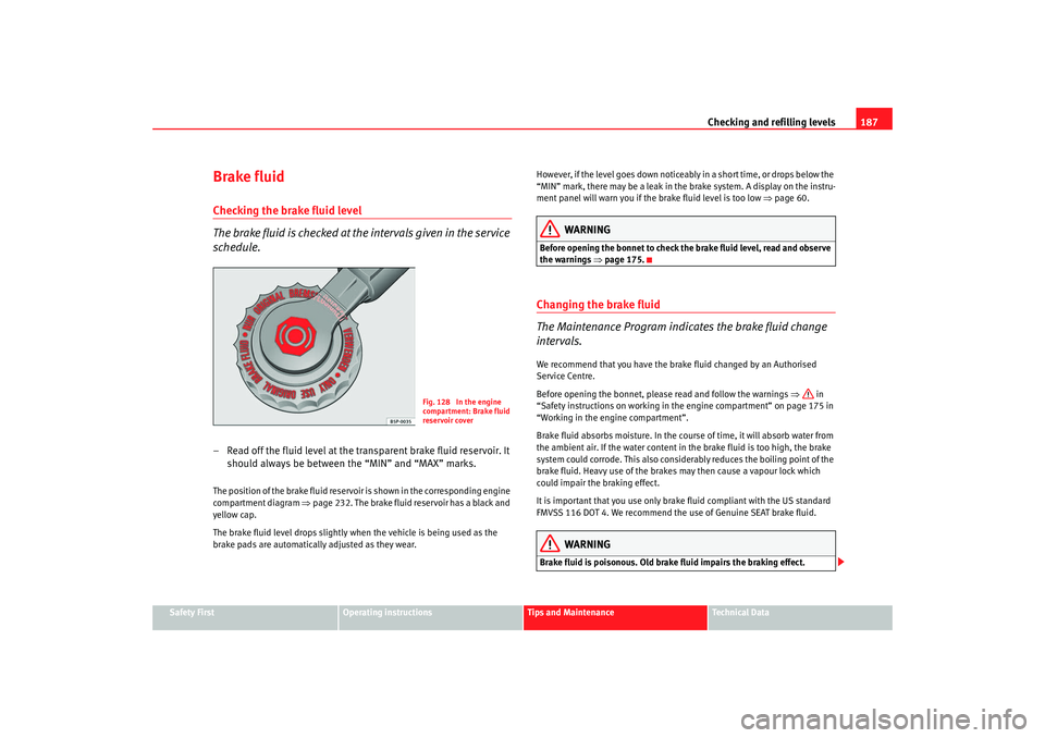
schedule.– Read off the fluid level at the transparent brake fluid reservoir. It
should always be between the “MIN” and “MAX” marks.The position of the brake fluid reservoir is shown in the corresponding engine
compartment diagram ⇒page 232. The brake fluid reservoir has a black and
yellow cap.
The brake fluid level drops slightly when the vehicle is being used as the
brake pads are automatically adjusted as they wear. However, if the level goes down noticeably in a short time, or drops below the
“MIN” mark, there may be a leak in the brake system. A display on the instru-
ment panel will warn you if the brake fluid level is too low
⇒page 60.
WARNING
Before opening the bonnet to check the brake fluid level, read and observe
the warnings ⇒ page 175.Changing the brake fluid
The Maintenance Program indicates the brake fluid change
intervals.We recommend that you have the brake fluid changed by an Authorised
Service Centre.
Before opening the bonnet, please read and follow the warnings ⇒ in
“Safety instructions on working in the engine compartment” on page 175 in
“Working in the engine compartment”.
Brake fluid absorbs moisture. In the course of time, it will absorb water from
the ambient air. If the water content in the brake fluid is too high, the brake
system could corrode. This also considerably reduces the boiling point of the
brake fluid. Heavy use of the brakes may then cause a vapour lock which
could impair the braking effect.
It is important that you use only brake fluid compliant with the US standard
FMVSS 116 DOT 4. We recommend the use of Genuine SEAT brake fluid.
WARNING
Brake fluid is poisonous. Old brake fluid impairs the braking effect.
Fig. 128 In the engine
compartment: Brake fluid
reservoir cover
COR_ING_0707 Seite 187 Mittwoch, 1. August 2007 6:25 18
Page 190 of 258
Checking and refilling levels
188•
Before opening the bonnet to check the brake fluid level, read and
observe the warnings ⇒ page 175.
•
Brake fluid should be stored in the closed original container in a safe
place out of reach of children. There is a toxic risk.
•
Complete the brake fluid change according to the Maintenance
Program. Heavy use of the brakes may cause a vapour lock if the brake fluid
is left in the system for too long. This would seriously affect the efficiency
of the brakes and the safety of the vehicle. This may cause an accident.Caution
Brake fluid could damage the paintwork. Wipe off any brake fluid from the
paintwork immediately.
For the sake of the environment
Brake fluid must be drained and disposed of in the proper manner observing
environmental regulations.
BatteryWarnings on handling the battery
WARNING
Always be aware of the danger of injury and chemical burns as well as the
risk of accident or fire when work ing on the battery and the electrical
system:•
Wear eye protection. Protect your eyes, skin and clothing from acid and
particles containing lead.
•
Battery acid is very corrosive and caustic. Wear protective gloves and
eye protection. Do not tilt the batter ies. This could spill acid through the
vents. Rinse battery acid from eyes immediately for several minutes with
clear water. Then seek medical care immediately. Neutralize any acid
splashes on the skin or clothing with a soapy solution, and rinse off with
plenty of water. If acid is swallowed by mistake, consult a doctor immedi-
ately.
•
Fires, sparks, naked lights and smoking are prohibited. When handling
cables and electrical equipment, avoid causing sparks and electrostatic
WARNING (continued)
Wear eye protection
Battery acid is very corrosive and caustic. Wear protec-
tive gloves and eye protection!
Fires, sparks, naked lights and smoking are prohibited!
A highly explosive mixture of gases is released when the
battery is under charge.
Keep children away from acid and batteries!
COR_ING_0707 Seite 188 Mittwoch, 1. August 2007 6:25 18
Page 199 of 258
If and when197
Safety First
Operating instructions
Tips and Maintenance
Te c h n i c a l D a t a
Snow chains
For technical reasons, snow chains must not
be used on the compact tempo-
rary spare wheel.
If you should have a puncture on one of the front wheels when using snow
chains, fit the compact temporary spare in place of one of the rear wheels.
You can then attach the snow chains to the wheel taken from the rear and use
this wheel to replace the punctured front wheel.
WARNING
•
The tyre pressures must be checked and corrected as soon as possible.
•
Do not drive faster than 80 km/h. Higher speeds can cause an accident.
•
Avoid heavy acceleration, hard braking and fast cornering, risk of acci-
dent.
•
Never use two or more compact spare tyres at the same time, risk of
accident.
•
No other type of tyre (normal summer or winter tyre) may be fitted on
the compact temporary spare wheel rim.
Tyre repair kit*
The tyre repair kit (for vehicles not including a spare wheel) is
stored under the floor panel in the luggage compartment.Your vehicle is equipped with the Tyre Mobility System “Tyre repair kit”.
The tyre repair kit consists of a contai ner with sealing compound to repair the
puncture and a compressor to generate the required tyre pressure. The kit will
reliably seal punctures up to a size of about 4 mm caused by the penetration
of a foreign body into the tyre.
Note
•
Seek professional assistance if the repair of a tyre puncture is not
possible with the sealing compound.
Wheel changePreparation work
What you must do before changing a wheel.– If you have a flat tyre or puncture, park the vehicle as far away from the flow of traffic as possible. Choose a location that is as
level as possible.
– All passengers should leave the vehicle. They should wait in a
safe area (for instance behind the roadside crash barrier).
– Switch off the engine. Switch on the hazard warning lights.
–Apply the handbrake firmly.
– Engage the first gear , or put the selector lever to position P for
those vehicles with an automatic gearbox.
– If you are towing a trailer, unhitch it from your vehicle.
– Take the vehicle tools and the spare wheel out of the luggage
compartment.
COR_ING_0707 Seite 197 Mittwoch, 1. August 2007 6:25 18
Page 206 of 258
If and when
204
NoteSeek professional assistance if the repair of a tyre puncture is not possible
with the sealing compound.Preparation work
Certain steps must be taken before repairing a tyre.– If you have a flat tyre or puncture, park the vehicle as far away from the flow of traffic as possible.
–Apply the handbrake firmly.
– Engage the first gear, of put the selector lever to position P.
– All passengers should leave the vehicle. They should wait in a
safe area (for instance behind the roadside crash barrier).
– Check whether a repair is possible using the Tyre Mobility System “General information and safety notes.”
– Unscrew inflation cap from the affected wheel.
– Take the tyre repair kit out of the luggage compartment.
WARNING
Put the hazard warning lights on and pl ace the warning triangle in position.
This is for your own safety and also warns other road users.
Caution
Take special care if you have to repair a tyre on a gradient.
Note
Please observe legal requirements when doing so.Tyre repair
The following sections describe the procedures for repairing
a tyre.Using the sealing compound
– The instructions on the container give detailed information on how to use the sealing compound.
Inflating the tyre.
– Remove the air compressor and hose from the container.
– Screw the retaining nut onto the valve.
– Plug the compressor cable into a 12 volt socket.
– Turn on compressor and monitor the pressure shown on the pres- sure gauge.
Completing the repair
– Remove the compressor hose from the valve.
– Fit the valve cap.
– Unplug the compressor from the socket.
– Return all tools to their proper storing location.
COR_ING_0707 Seite 204 Mittwoch, 1. August 2007 6:25 18
Page 209 of 258

If and when207
Safety First
Operating instructions
Tips and Maintenance
Te c h n i c a l D a t a
Fuses on left side of dash panelFuses
Number Consumer Amperes
1 Secondary water pump 1.8 20 VT (T16) 15
2A BS/E S P 10
3 Vacant
4 Brake light, clutch switch, relay coils 5
5 Engine control unit (petrol) 5
6 Right side light 5
7 Left side light 5
8 Mirror heating unit 5
9 Lambda probe 10
10 Signal“S”
a). Radio unit 5
11 Electric mirror power supply 5
12 Headlamp height adjustment 5
13 Oil pressure/level sensor 5
14 Additional heating engine/fuel pump 10
15 Automatic gearbox unit 10
16 Heated seats 15
17 Engine control unit 5
18 Instrument panel /Heating and ventilation, Navigation, Headlamp height adjustment, Electric mirror 10
19 Reversing light 10
20 Windscreen washer pump 10
21 Main beam headlight, right 10
COR_ING_0707 Seite 207 Mittwoch, 1. August 2007 6:25 18
Page 210 of 258

If and when
208
22 Main beam headlight, left 10
23 Number plate light/si de light indicator 5
24 Rear windscreen wiper 10
25 Injectors(fuel) 10
26 Brake light switch /ESP (Turn sensor) 10
27 Instrument panel/Diagnosis 5
28 Switchboard: glovebox light, boot light, interior light 10
29 Climatronic 5
30 Power supply central locking unit 5
31 Left front window control 25
32 Vacant
33 Self powered alarm horn 15
34 Engine control unit 15
35 Sunroof 20
36 Engine ventilator heating /blower 25
37 Headlight washer pump 20
38 Front and rear fog lights 15
39 Engine control unit (petrol) 15
40 Engine control unit diesel + SDI Fuel pump 30
41 Fuel gauge 15
42 Ignition transformer+ Engine control unit T70 15
43 Dipped headlight (right side) 15
44 Left rear window control 25
45 Front right window control 25
Number
Consumer Amperes
COR_ING_0707 Seite 208 Mittwoch, 1. August 2007 6:25 18
Page 213 of 258

If and when211
Safety First
Operating instructions
Tips and Maintenance
Te c h n i c a l D a t a
Bulb changeGeneral notesBefore changing any bulb, first turn off the equipment concerned.
Do not touch the bulb glass. Fingerprints vaporise in the heat, causing a
reduction in the bulb life and condensation on the mirror surface, thus
reducing efficiency.
A bulb should only be replaced by one of the same type. The type is inscribed
on the bulb, either on the glass part or on the base.
It is highly recommended to keep a box of spare bulbs in the vehicle. At the
very least, the bulbs that most affect road safety should have spares in the
vehicle.
Rear lights on frame
Brake/position 12V/P21/5W
Turn signals 12V/P21W Rear lights on tailgate
small position light 12V/W5W
antifog lamp 12V/P21W
reverse lamp 12V/P21W
Single reflector headlamps*
full beam/dipped 12V 60/55W (H4)
turn signals 12V/PY21W
position lights 12/W5W
Double reflector headlamps
dipped beam 12V/55W (H7)
roadway 12V/55W (H3)
turn signals 12V/PY21W
position lights 12V/W5W
Xenon headlights
7)
Dipped beam 12V/35W (D1S)
8)
roadway 12V/55W (H7)
10
Cable control unit 5
11 Clima fan 5
12 Vacant
13 Jatco unit for automatic gearbox 5
14 Vacant
15 Vacant
16 Vacant
Number
Consumer Amperes
COR_ING_0707 Seite 211 Mittwoch, 1. August 2007 6:25 18
Page 221 of 258
If and when219
Safety First
Operating instructions
Tips and Maintenance
Te c h n i c a l D a t a
– Remove plastic cover ⇒page 218, fig. 153 , insert finger in
opening and pull in the direction of the arrow.
–Press the tabs ⇒ page 218, fig. 154 of the lamp holder and
remove lampholder.
– Turn bigger lamp 1/4 turn to left. For the small lamp, rotate and extract the lamp holder and pull on the lamp.
– Remove lamp and replace.
– Fit the bigger lamp, pressing inwards and turn 1/4 turn to the right. Place the smaller lamp in casing and press.
– Carefully fit the lampholder in the casing and press until a “clic” is heard.
– Next replace the cover and press down.
NoteMake sure that when assembling all seals and rubbers are correctly fitted.
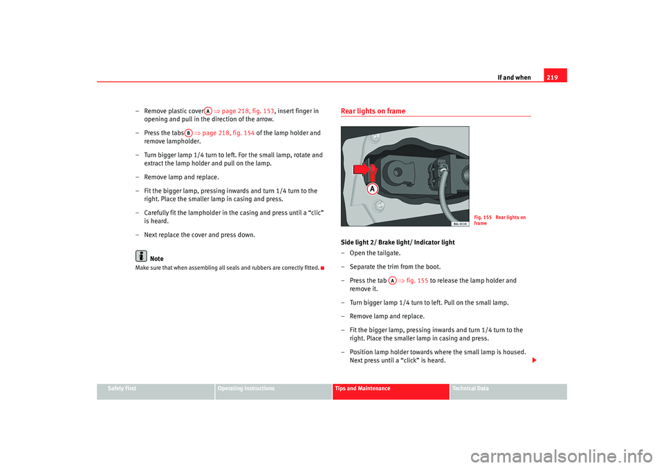
Rear lights on frameSide light 2/ Brake light/ Indicator light
–Open the tailgate.
– Separate the trim from the boot.
– Press the tab ⇒fig. 155 to release the lamp holder and
remove it.
– Turn bigger lamp 1/4 turn to left. Pull on the small lamp.
– Remove lamp and replace.
– Fit the bigger lamp, pressing inwards and turn 1/4 turn to the right. Place the smaller lamp in casing and press.
– Position lamp holder towards where the small lamp is housed. Next pre ss u
ntil a “cli ck” is heard.
AA
AB
Fig. 155 Rear lights on
frame
AA
COR_ING_0707 Seite 219 Mittwoch, 1. August 2007 6:25 18
Page 222 of 258
If and when
220
NoteMake sure that when assembling all seals and rubbers are correctly fitted.Number plate light– Release transparent lamp cover by levering the tab with the flat part of a screwdriver.
– Remove the defective lamp from the lamp holder, holding it in the centre, press to one side and fit new lamp.
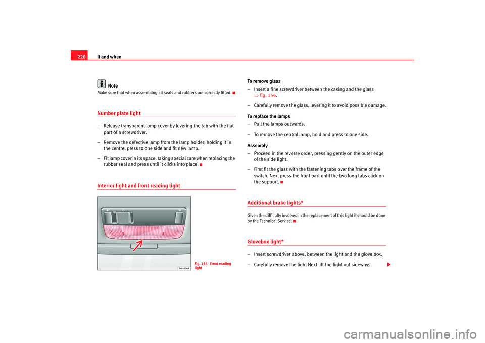
– Fit lamp cover in its space, taking special care when replacing the rubber seal and press until it clicks into place.Interior light and front reading light
To r e m o v e g l a s s
– Insert a fine screwdriver between the casing and the glass ⇒fig. 156.
– Carefully remove the glass, levering it to avoid possible damage.
To replace the lamps
– Pull the lamps outwards.
– To remove the central lamp, hold and press to one side.
Assembly
– Proceed in the reverse order, pressing gently on the outer edge of the side light.
– First fit the glass with the fastening tabs over the frame of the switch. Next press the front part until the two long tabs click on
the support.Additional brake lights*Given the difficulty involved in the replacement of this light it should be done
by the Technical Service.Glovebox light*– Insert screwdriver above, between the light and the glove box.
– Carefully remove the light Next lift the light out sideways.
Fig. 156 Front reading
light
COR_ING_0707 Seite 220 Mittwoch, 1. August 2007 6:25 18
Page 225 of 258

If and when223
Safety First
Operating instructions
Tips and Maintenance
Te c h n i c a l D a t a
WARNING
•
Please note the safety warnings referring to working in the engine
compartment ⇒page 175, “Working in the engine compartment”.
•
The battery providing assistance must have the same voltage as the flat
battery (12V) and approximately the same capacity (see imprint on
battery). Failure to comply could result in an explosion.
•
Never use jump leads when one of the batteries is frozen. Danger of
explosion! Even after the battery has thawed, battery acid could leak and
cause chemical burns. If a battery freezes, it should be replaced.
•
Keep sparks, flames and lighted cigarettes away from batteries, danger
of explosion. Failure to comply could result in an explosion.
•
Observe the instructions provided by the manufacturer of the jump
leads.
•
Do not connect the negative cable from the other vehicle directly to the
negative terminal of the flat battery. The gas emitted from the battery could
be ignited by sparks. Danger of explosion.
•
Do not attach the negative cable from the other vehicle to parts of the
fuel system or to the brake line.
•
The non-insulated parts of the battery clamps must not be allowed to
touch. The jump lead attached to the positive battery terminal must not
touch metal parts of the vehicle, this can cause a short circuit.
•
Position the leads in such a way that they cannot come into contact
with any moving parts in the engine compartment.
•
Do not bend over the batteries. This could result in chemical burns.Note
The vehicles must not touch each other, otherwise electricity could flow as
soon as the positive terminals are connected.
COR_ING_0707 Seite 223 Mittwoch, 1. August 2007 6:25 18