clock Seat Exeo 2010 Owner's manual
[x] Cancel search | Manufacturer: SEAT, Model Year: 2010, Model line: Exeo, Model: Seat Exeo 2010Pages: 319, PDF Size: 9.64 MB
Page 13 of 319
Safe driving11
Safety First
Operating Instructions
Practical Tips
Technical Specifications
– Fasten your seat belt securely ⇒page 18.
– Keep both feet in the footwell so that you have the vehicle under control at all times.Adjustment of the driver seat ⇒page 134.
WARNING
•An incorrect sitting position of the driver can lead to severe injuries.•Adjust the driver seat so that there is at least 25 cm distance between
the centre of the chest and the centre of the steering wheel ⇒page 10,
fig. 1 . If you are sitting closer than 25 cm, the airbag system cannot protect
you properly.•If your physical constitution prevents you from maintaining the
minimum distance of 25 cm, contact a specialised workshop. The work-
shop will help you decide if special specific modifications are necessary.•When driving, always hold the steering wheel with both hands on the
outside of the ring at the 9 o’clock and 3 o’clock positions. This reduces the
risk of injury when the driver airbag is triggered.•Never hold the steering wheel at the 12 o’clock position, or in any other
manner (e.g. in the centre of the steering wheel). In such cases, if the
airbag is triggered, you may sustain injuries to the arms, hands and head.•To reduce the risk of injury to the driver during sudden braking manoeu-
vres or an accident, never drive with the backrest tilted far back! The airbag
system and seat belts can only provide optimal protection when the back-
rest is in an upright position and the driver is wearing his or her seat belt
properly. The further the backrests are tilted to the rear, the greater the risk
of injury due to incorrect positioning of the belt web or to the incorrect
sitting position!•Adjust the head restraint properly to achieve optimal protection.
Proper sitting position for front passenger
The front passenger must sit at least 25 cm away from the
dash panel so that the airbag can provide the greatest
possible protection in the event that it is triggered.For your own safety and to reduce the risk of injury in the event of an
accident, we recommend the following adjustments for the front
passenger:
– Move the front passenger seat back as far as possible ⇒.
– Move the backrest to an upright position so that your backrests completely against it.
– Adjust the head restraint so that its upper edge is at the same level as the top of your head, or as close as possible to the same
level as the top of your head ⇒ page 13.
– Keep both feet in the footwell in front of the front passenger seat.
– Fasten your seat belt securely ⇒page 18.It is possible to deactivate the passenger airbag in exceptional circum-
stances ⇒ page 23.
Adjusting the front passenger seat ⇒page 134.
WARNING
•An incorrect sitting position of the front passenger can lead to severe
injuries.•Adjust the front passenger seat so that there is at least 25 cm between
your chest and the dash panel. If you are sitting closer than 25 cm, the
airbag system cannot protect you properly.
exeo_EN.book Seite 11 Montag, 30. August 2010 4:45 16
Page 61 of 319
Cockpit59
Safety First
Operating Instructions
Practical Tips
Technical Specifications
InstrumentsInstrument panel overview
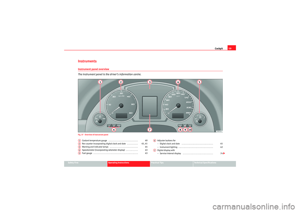
The instrument panel is the driver’s information centre.Fig. 37 Overview of instrument panel
Coolant temperature gauge . . . . . . . . . . . . . . . . . . . . . . . . . . .
Rev counter incorporating digital clock and date . . . . . . . . . .
Warning and indicator lamps . . . . . . . . . . . . . . . . . . . . . . . . . .
Speedometer (incorporating odometer display) . . . . . . . . . . .
Fuel gauge . . . . . . . . . . . . . . . . . . . . . . . . . . . . . . . . . . . . . . . . . Adjuster buttons for
−
Digital clock and date . . . . . . . . . . . . . . . . . . . . . . . . . . . . .
− Instrument lighting . . . . . . . . . . . . . . . . . . . . . . . . . . . . . . . .
Digital display with
− Service interval display . . . . . . . . . . . . . . . . . . . . . . . . . . . .
A1
60
A2
61, 61
A3
65
A4
63
A5
63
A6
61
62
A7
74
exeo_EN.book Seite 59 Montag, 30. August 2010 4:45 16
Page 63 of 319
Cockpit61
Safety First
Operating Instructions
Practical Tips
Technical Specifications
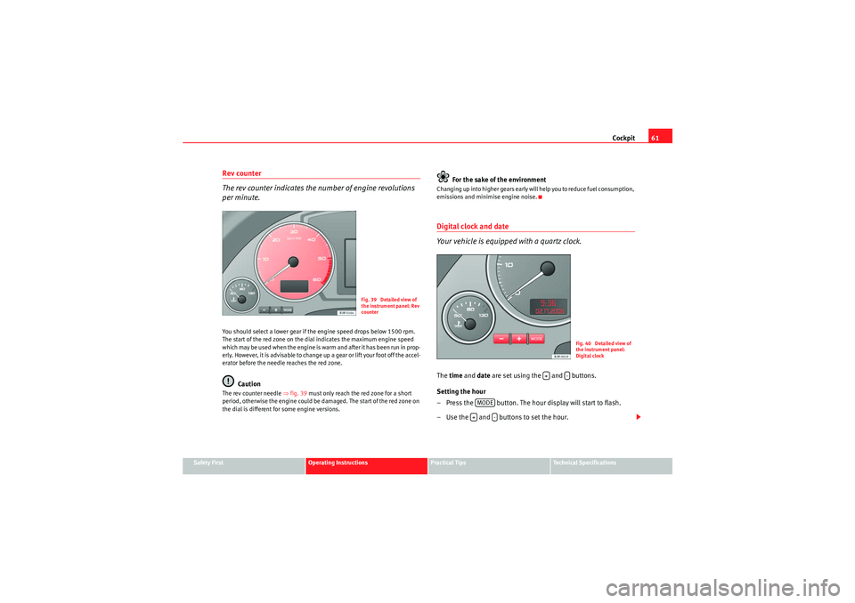
Rev counter
The rev counter indicates the number of engine revolutions
per minute.You should select a lower gear if the engine speed drops below 1500 rpm.
The start of the red zone on the dial indicates the maximum engine speed
w hich may b e us ed wh en the e ngin e is war m a nd af te r it has b e e n r un i n p rop -
erly. However, it is advisable to change up a gear or lift your foot off the accel-
erator before the needle reaches the red zone.
Caution
The rev counter needle ⇒fig. 39 must only reach the red zone for a short
period, otherwise the engine could be damaged. The start of the red zone on
the dial is different for some engine versions.
For the sake of the environment
C h a n g i ng u p i n t o h i g h e r ge a r s e a r l y wi ll h e l p yo u t o r e d u ce f u e l co ns u m p t i o n ,
emissions and minimise engine noise.Digital clock and date
Your vehicle is equipped with a quartz clock.The time and date are set using the and buttons.
Setting the hour
– Press the button. The hour display will start to flash.
– Use the and buttons to set the hour.
Fig. 39 Detailed view of
the instrument panel: Rev
counter
Fig. 40 Detailed view of
the instrument panel:
Digital clock
+
-
MODE+
-
exeo_EN.book Seite 61 Montag, 30. August 2010 4:45 16
Page 64 of 319
Cockpit
62
Setting the minutes
– Keep pressing the button until the minutes display flashes.
– Use the and buttons to set the minutes.
Setting the date
– Keep pressing the button until the date display (day) flashes.
– Use the and buttons to set the day.
– Keep pressing the button until the month display flashes.
– Use the and buttons to set the month.
– Keep pressing the button until the year display flashes.
– Use the and buttons to set the year.
Deactivating the date display
– Keep pressing the button until the complete date display flashes.
– Use the button to disable the date display.
Activating the date display
– Keep pressing the button until the complete date display flashes.
– Use the button to enable the date display.When the display stops flashing, this means the setting you are performing
is completed and the time and date have been successfully stored. When the ignition is switched off, the odometer and the digital clock with
date display can be switched on for a few seconds by pressing the CHECK
button
⇒page 59, fig. 37 .
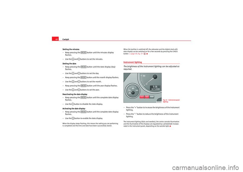
Instrument lighting
The brightness of the instrument lighting can be adjusted as
required.– Press the "+" button to increase the brightness of the instrument
lighting.
– Press the "-" button to reduce the brightness of the instrument lighting.The instrument lighting (dials and needles), the centre console illumination
and the illumination of the displays are regulated by a photodiode incorpo-
rated in the instrument panel, depending on the outside light.
MODE
+
-MODE
+
-MODE
+
-MODE
+
-MODE
-
MODE
+
A8
Fig. 41 Instrument panel
lighting
exeo_EN.book Seite 62 Montag, 30. August 2010 4:45 16
Page 66 of 319
Cockpit
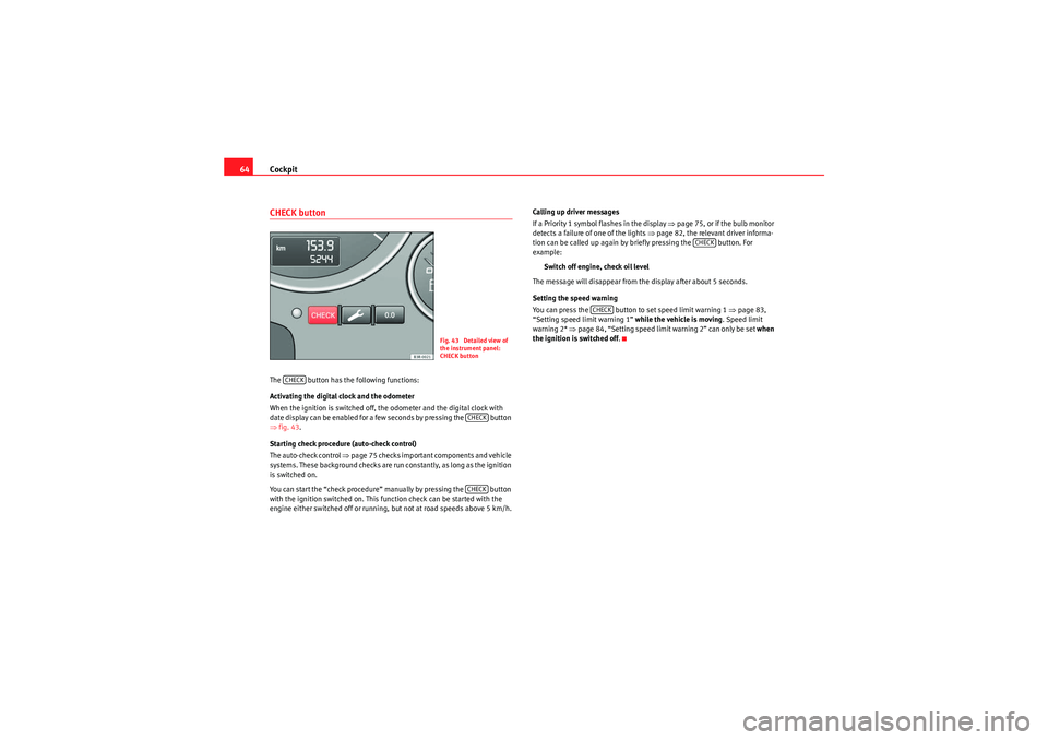
64CHECK buttonThe button has the following functions:
Activating the digital clock and the odometer
When the ignition is switched off, the odometer and the digital clock with
date display can be enabled for a few seconds by pressing the button
⇒ fig. 43 .
Starting check procedure (auto-check control)
The auto-check control ⇒page 75 checks important components and vehicle
systems. These background checks are run constantly, as long as the ignition
is switched on.
You can start the “check procedure” manually by pressing the button
with the ignition switched on. This function check can be started with the
engine either switched off or running, but not at road speeds above 5 km/h. Calling up driver messages
If a Priority 1 symbol flashes in the display
⇒page 75, or if the bulb monitor
detects a failure of one of the lights ⇒page 82, the relevant driver informa-
tion can be called up again by briefly pressing the button. For
example:
Switch off engine, check oil level
The message will disappear from the display after about 5 seconds.
Setting the speed warning
You can press the button to set speed limit warning 1 ⇒page 83,
“Setting speed limit warning 1” while the vehicle is moving. Speed limit
warning 2* ⇒ page 84, “Setting speed limit warning 2” can only be set when
the ignition is switched off .
Fig. 43 Detailed view of
the instrument panel:
CHECK button
CHECK
CHECKCHECK
CHECK
CHECK
exeo_EN.book Seite 64 Montag, 30. August 2010 4:45 16
Page 86 of 319
Cockpit
84
Clearing the speed limit
– Drive the vehicle at a minimum of 5 km/h.
– Press the CHECK button for at least two seconds.The speed warning symbol
lights up briefly in the display when the button
is released to confirm that the selected speed has been stored. The speed
limit that has been selected remains st ored until another speed is selected
with a brief push of the button, or until the memory is cleared with a long
push of the button.
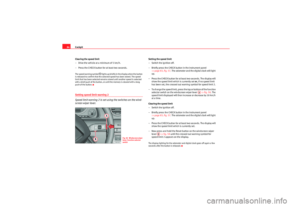
Setting speed limit warning 2
Speed limit warning 2 is set using the switches on the wind-
screen wiper lever.
Setting the speed limit
– Switch the ignition off.
– Briefly press the CHECK button in the instrument panel ⇒page 83, fig. 57 . The odometer and the digital clock will light
up.
– Press the CHECK button for at least two seconds. The display will show the speed limit which is currently set or, if no speed limit
has been set, the cr ossed out warning symbol for speed limit 2.
– To change the speed limit, press the top or bottom of the function selector switch on the windscreen wiper lever ⇒fig. 58 . The
speed limit displayed will then in crease or decrease by 10 km/h
at a time.
Clearing the speed limit
– Switch the ignition off.
– Briefly press the CHECK button in the instrument panel ⇒page 83, fig. 57 . The odometer and the digital clock will light
up.
– Press the CHECK button for at least two seconds. The display will show the speed limit which is currently set.
– Now press and hold the Reset button on the windscreen wiper lever ⇒fig. 58 until the crossed out warning symbol for
speed limit 2 appears on the display.The display lighting for the odometer and digital clock goes off again a few
seconds after the button is released.
Fig. 58 Windscreen wiper
lever: Function selector
switch
AA
AB
exeo_EN.book Seite 84 Montag, 30. August 2010 4:45 16
Page 88 of 319
Cockpit
86Driving time warning
After 2 hours of continuous driving, the display automatically switches over
to the driving time display of 2:00 . At the same time the driving time display
starts flashing. This is to remind the driver to take a break.
The driving time warning can be switched off by briefly pressing the function
selector switch or the button ⇒fig. 60 .
If you continue driving or take a break for less than 10 minutes, the driving
time warning will switch on once again when the total driving time is 4:00
hours, 6:00 h o u r s , e t c . H o w e v e r, i f yo u ta ke a b r e a k f o r m o r e t ha n 1 0 m i n u te s ,
the driving time warning clock will be erased.
Distance covered
This display shows the distance you have covered since the memory was last
cancelled. The longest possible distance which can be recorded is
9999.9 km.
Note
•The displays for fuel consumption (average and instantaneous), distance
to empty and speed are shown in metric units.•The information in the memory is lost if the battery is disconnected.
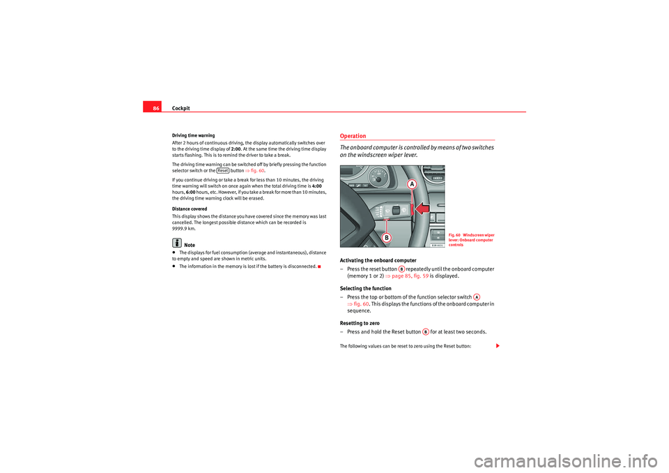
Operation
The onboard computer is controlled by means of two switches
on the windscreen wiper lever.Activating the onboard computer
– Press the reset button repeatedly until the onboard computer (memory 1 or 2) ⇒ page 85, fig. 59 is displayed.
Selecting the function
– Press the top or bottom of the function selector switch ⇒fig. 60 . This displays the functions of the onboard computer in
sequence.
Resetting to zero
– Press and hold the Reset button for at least two seconds.The following values can be reset to zero using the Reset button:
Reset
Fig. 60 Windscreen wiper
lever: Onboard computer
controls
AB
AA
AB
exeo_EN.book Seite 86 Montag, 30. August 2010 4:45 16
Page 90 of 319
Cockpit
88Some of your vehicle’s functions can be adjusted, activated and controlled by
menus . With the aid of the menus you can then also select the information
you wish to see displayed on the DIS display. This is only possible when the
ignition is on. The menu is enabled using the button on the wind-
screen wiper lever ⇒ page 87, fig. 61.
The main menu lists the different display types (or basic commands):
Programming
Check
Menu off
Help
The main menu options have the following submenus:
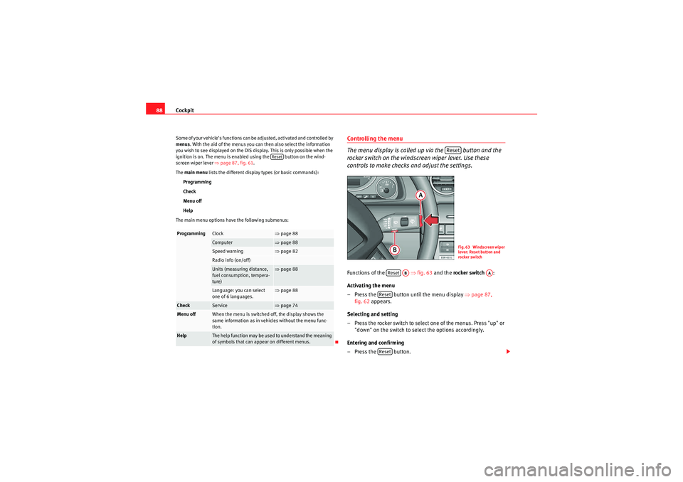
Controlling the menu
The menu display is called up via the button and the
rocker switch on the windscreen wiper lever. Use these
controls to make checks and adjust the settings.Functions of the ⇒fig. 63 and the rocker switch :
Activating the menu
– Press the button until the menu display ⇒page 87,
fig. 62 appears.
Selecting and setting
– Press the rocker switch to select one of the menus. Press "up" or "down" on the switch to select the options accordingly.
Entering and confirming
–Press the button.
Programming
Clock
⇒ page 88
Computer
⇒page 88
Speed warning
⇒page 82
Radio info (on/off)Units (measuring distance,
fuel consumption, tempera-
ture)
⇒page 88
Language: you can select
one of 6 languages.
⇒page 88
Check
Service
⇒page 74
Menu off
When the menu is switched off, the display shows the
same information as in vehicles without the menu func-
tion.
Help
The help function may be used to understand the meaning
of symbols that can appear on different menus.
Reset
Reset
Fig. 63 Windscreen wiper
lever: Reset button and
rocker switch
Reset
AB
AA
ResetReset
exeo_EN.book Seite 88 Montag, 30. August 2010 4:45 16
Page 222 of 319
Checking and refilling levels
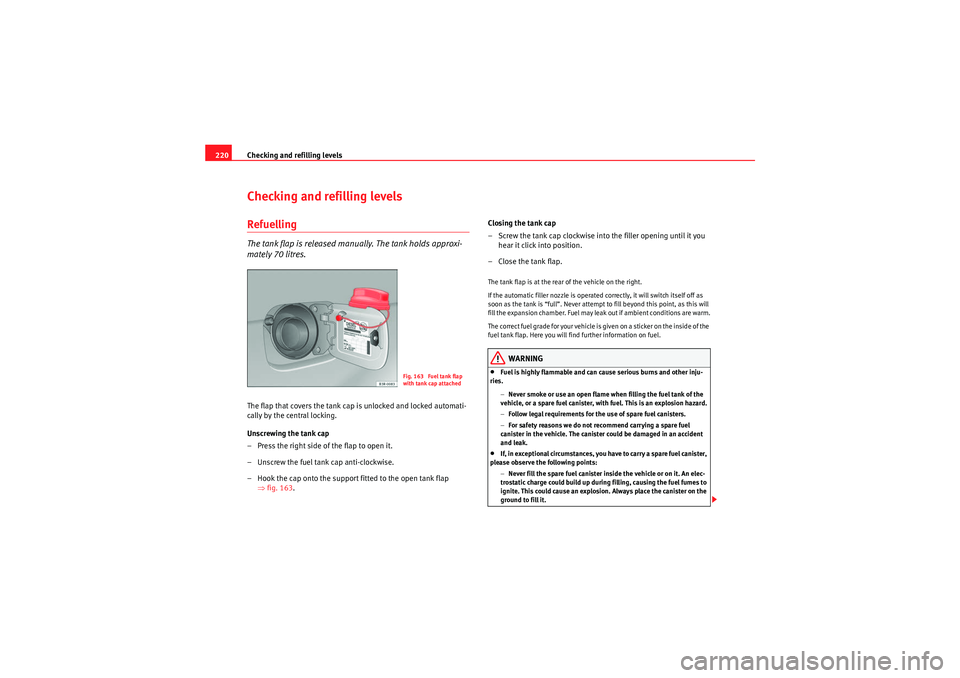
220Checking and refilling levelsRefuellingThe tank flap is released manually. The tank holds approxi-
mately 70 litres.The flap that covers the tank cap is unlocked and locked automati-
cally by the central locking.
Unscrewing the tank cap
– Press the right side of the flap to open it.
– Unscrew the fuel tank cap anti-clockwise.
– Hook the cap onto the support fitted to the open tank flap
⇒fig. 163 . Closing the tank cap
– Screw the tank cap clockwise into the filler opening until it you
hear it click into position.
– Close the tank flap.
The tank flap is at the rear of the vehicle on the right.
If the automatic filler nozzle is operated correctly, it will switch itself off as
soon as the tank is “full”. Never attempt to fill beyond this point, as this will
fill the expansion chamber. Fuel may leak out if ambient conditions are warm.
T he co rr ec t fu el g rad e fo r you r v eh icle is giv en on a sti cker o n th e i nsid e of the
fuel tank flap. Here you will find further information on fuel.
WARNING
•Fuel is highly flammable and can cause serious burns and other inju-
ries.
−Never smoke or use an open flame when filling the fuel tank of the
vehicle, or a spare fuel canister, with fuel. This is an explosion hazard.
− Follow legal requirements for the use of spare fuel canisters.
− For safety reasons we do not recommend carrying a spare fuel
canister in the vehicle. The canister could be damaged in an accident
and leak.•If, in exceptional circumstances, you have to carry a spare fuel canister,
please observe the following points:
−Never fill the spare fuel canister inside the vehicle or on it. An elec-
trostatic charge could build up during filling, causing the fuel fumes to
ignite. This could cause an explosion. Always place the canister on the
ground to fill it.
Fig. 163 Fuel tank flap
with tank cap attached
exeo_EN.book Seite 220 Montag, 30. August 2010 4:45 16
Page 231 of 319

Checking and refilling levels229
Safety First
Operating Instructions
Practical Tips
Technical Specifications
tion. The damage caused by the use of these antifreezes may lead to a loss of
coolant fluid, causing serious damage to the engine.
•G12++ antifreeze can be mixed only with antifreeze additives G11, G12
and G12+.Checking the coolant level
The coolant level can be checked visually.– Switch the ignition off.
– Check the coolant level on coolant fluid expansion tank ⇒fig. 168 . When the engine is cold, it should be between the
“min” and “max” marks. When the engine is hot, it may be
slightly above the “max” mark.Its location is shown in the corresponding general overview of the engine
compartment. The coolant level should be checked with the engine switched off.
The coolant level is monitored by a warning lamp on the instrument panel
display
⇒page 78. However, we recommend that it should be checked occa-
sionally.
Coolant fluid loss
Any loss of coolant fluid normally indicates a leak in the cooling system. In
this case the cooling system should be inspected by a qualified workshop
without delay. It is not sufficient merely to top up the coolant fluid.
If there are no leaks in the system, a loss of coolant fluid can only occur if the
coolant boils and is forced out of the system as a result of overheating.
Caution
Radiator sealants must not be added to the coolant fluid. Such additives
could seriously impair the function of the cooling system.To p p i n g u p t h e c o o l a n t f l u i d
Be careful when topping up with coolant fluid.– Switch the engine off.
– Wait for the engine to cool down.
– Cover the cap on the expansion tank ⇒fig. 168 with a cloth, and
carefully unscrew the cap anti-clockwise ⇒.
– Add coolant fluid.
– Screw on the cap tightly.
Fig. 168 Engine compart-
ment: Coolant fluid
deposit
exeo_EN.book Seite 229 Montag, 30. August 2010 4:45 16