ignition Seat Exeo 2010 Owner's Guide
[x] Cancel search | Manufacturer: SEAT, Model Year: 2010, Model line: Exeo, Model: Seat Exeo 2010Pages: 319, PDF Size: 9.64 MB
Page 76 of 319
Cockpit
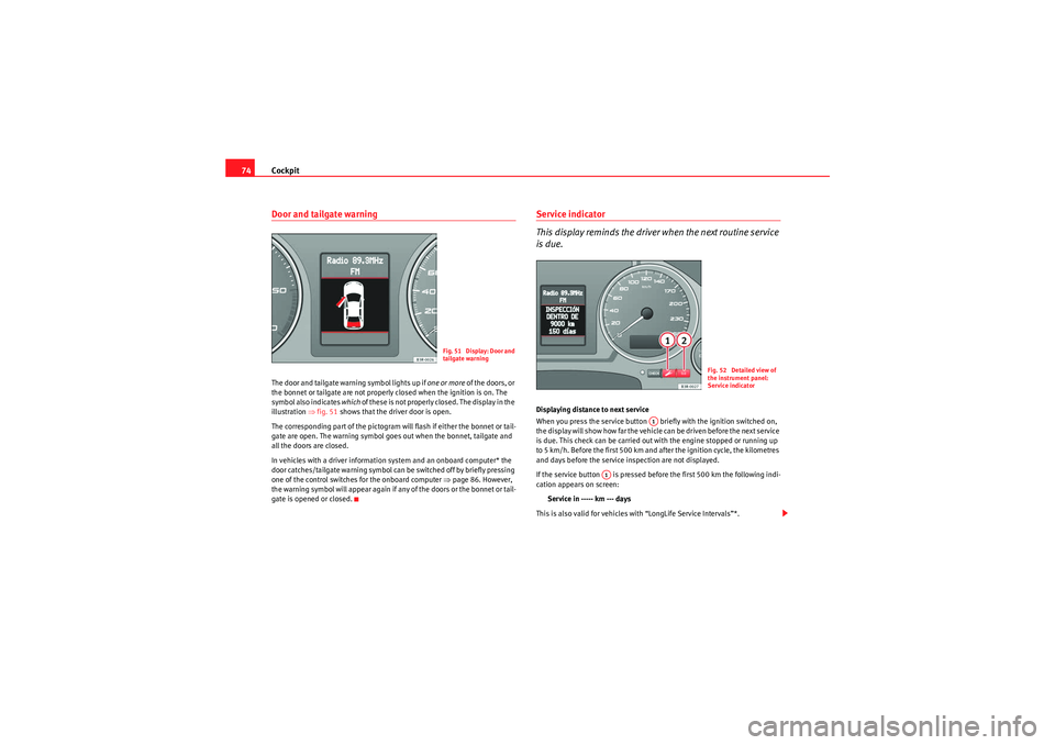
74Door and tailgate warningThe door and tailgate warning symbol lights up if one or more of the doors, or
the bonnet or tailgate are not properly closed when the ignition is on. The
symbol also indicates which of these is not properly closed. The display in the
illustration ⇒fig. 51 shows that the driver door is open.
The corresponding part of the pictogram will flash if either the bonnet or tail-
gate are open. The warning symbol goes out when the bonnet, tailgate and
all the doors are closed.
In vehicles with a driver information system and an onboard computer* the
door catches/tailgate warning symbol can be switched off by briefly pressing
one of the control switches for the onboard computer ⇒page 86. However,
the warning symbol will appear again if any of the doors or the bonnet or tail-
gate is opened or closed.
Service indicator
This display reminds the driver when the next routine service
is due.Displaying distance to next service
When you press the service button briefly with the ignition switched on,
the display will show how far the vehicle can be driven before the next service
is due. This check can be carried out with the engine stopped or running up
to 5 km/h. Before the first 500 km and after the ignition cycle, the kilometres
and days before the service inspection are not displayed.
If the service button is pressed before the first 500 km the following indi-
cation appears on screen:
Service in ----- km --- days
This is also valid for vehicles with “LongLife Service Intervals”*.
Fig. 51 Display: Door and
tailgate warning
Fig. 52 Detailed view of
the instrument panel:
Service indicator
A1
A1
exeo_EN.book Seite 74 Montag, 30. August 2010 4:45 16
Page 77 of 319

Cockpit75
Safety First
Operating Instructions
Practical Tips
Technical Specifications
Service reminder
The instrument panel controls the distance travelled every day. It calculates
the average of these distances travelled and activates the service reminder
sufficiently in advance.
The display reverts back to the standard display after about 5 seconds. The
remaining distance to the next service is updated every time the ignition is
switched on, until the service becomes due.
Service due
When a service is due,
SERVICE! will appear in the display immediately after
you switch on the ignition. The display reverts back to the standard display
after about 5 seconds.
Resetting the display
The display is reset by the workshop after the service has been carried out.
The service interval will be set to a LongLife Service (flexible service interval)
or Inspection Service (fixed service interval), depending on which engine oil
is used. It is only possible to reset the display via the instrument panel when
a n o i l cha n ge i s p e r f o r m e d ; i n t h is cas e t h e d is p l a y ca n o n l y b e r e s e t t o a f i xe d
service interval of 15,000 km. Proceed as follows:
•Switch the ignition off.•Press the service button ⇒page 74, fig. 52 and hold while switching
on the ignition. The display will show one of these messages: Service in -----
km or Service!•Now press and hold the reset button until the display shows Service
in ----- km --- days or Service!
The display switches out of the reset mode if you do not press the reset button
within 5 seconds.Caution
The system cannot calculate the figures for the service interval display if the
battery is disconnected from the vehicle, so no service reminder can be displayed during this time. Please remember that it is essential to service the
vehicle within the established time limits to prevent its deterioration and to
extend its useful life (particularly that of the engine). The period between two
services must never be longer than the time specified in the Maintenance
Programme, even if you only cover a low mileage during this time.
Note
•Do not reset the service indicator between services, otherwise the display
will be incorrect.•The information in the service indicator remains intact if the battery is
disconnected.•The distance to the next service cannot be called up if the system has
detected a Priority 1 fault (red symbol).Auto-check systemIntroductionThe auto-check system checks important components and vehicle systems.
These background checks are run constantly, as long as the ignition is
switched on.
A message is displayed on the instrument panel if a fault should occur or if
any maintenance or repairs are urgently required. This is accompanied by an
audible warning signal. Depending on the priority of the fault, a red or yellow
warning symbol lights up on the display.
The red symbol indicates danger, whereas the yellow one represents a
warning . Additional messages for the driver may be shown with the red or
yellow symbols.
A1
A2
exeo_EN.book Seite 75 Montag, 30. August 2010 4:45 16
Page 85 of 319
Cockpit83
Safety First
Operating Instructions
Practical Tips
Technical Specifications
e xcee d ed by a b out 10 k m / h. A war ni ng s y m b ol will als o a ppear in t he display
⇒
fig. 56 .
The speed warning function has two different warning speeds, which operate
independently and serve slightly different purposes:
Speed limit warning 1
With speed limit warning 1, the maximum speed can be changed while
driving. The speed limit that has been set remains stored until the ignition is
switched off, or until it is changed or cleared.
The warning symbol
for speed limit warning 1 ⇒page 82, fig. 56 will
appear in the display if you exceed the pre-set speed. It goes out again if the
speed is reduced below the set speed limit.
The symbol also goes out if the speed is increased to more than about
40 km/h above the set speed for at least 10 seconds. However, this does not
cancel the speed limit that was originally set.
Setting speed limit warning 1 ⇒page 83.
Speed limit warning 2
With speed limit warning 2, the speed limit can only be changed or cleared
when the ignition is switched off. You are recommended to store this speed
limit warning if you always wish to be reminded of a particular speed limit.
This could be when driving in countries with general speed limits, or if a
particular speed should not be exceeded when winter tyres are fitted etc.
The speed limit warning symbol
for speed warning 2 will appear in the
display if you exceed the pre-set speed. Unlike speed limit warning 1, the
warning symbol only goes out once the road speed has dropped below the
set value again.
Setting speed limit warning 2 ⇒page 84.
Note
Please bear in mind that, even with the speed warning function, it is still
important to keep a eye on the vehicle’s speed with the speedometer and to
observe the legal speed limits.Setting speed limit warning 1
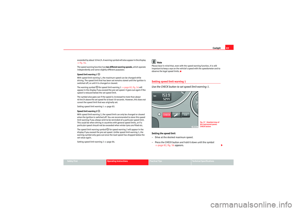
Use the CHECK button to set speed limit warning 1.Setting the speed limit
– Drive at the desired maximum speed.
– Press the CHECK button and hold it down until the symbol
⇒page 82, fig. 56 appears.
Fig. 57 Detailed view of
the instrument panel:
CHECK button
exeo_EN.book Seite 83 Montag, 30. August 2010 4:45 16
Page 86 of 319
Cockpit
84
Clearing the speed limit
– Drive the vehicle at a minimum of 5 km/h.
– Press the CHECK button for at least two seconds.The speed warning symbol
lights up briefly in the display when the button
is released to confirm that the selected speed has been stored. The speed
limit that has been selected remains st ored until another speed is selected
with a brief push of the button, or until the memory is cleared with a long
push of the button.
Setting speed limit warning 2
Speed limit warning 2 is set using the switches on the wind-
screen wiper lever.
Setting the speed limit
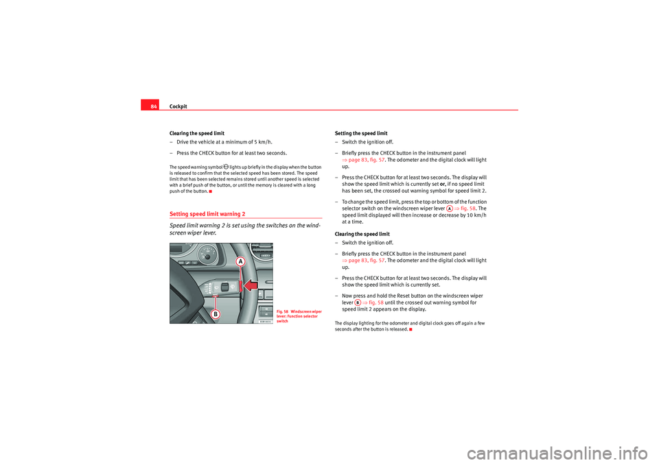
– Switch the ignition off.
– Briefly press the CHECK button in the instrument panel ⇒page 83, fig. 57 . The odometer and the digital clock will light
up.
– Press the CHECK button for at least two seconds. The display will show the speed limit which is currently set or, if no speed limit
has been set, the cr ossed out warning symbol for speed limit 2.
– To change the speed limit, press the top or bottom of the function selector switch on the windscreen wiper lever ⇒fig. 58 . The
speed limit displayed will then in crease or decrease by 10 km/h
at a time.
Clearing the speed limit
– Switch the ignition off.
– Briefly press the CHECK button in the instrument panel ⇒page 83, fig. 57 . The odometer and the digital clock will light
up.
– Press the CHECK button for at least two seconds. The display will show the speed limit which is currently set.
– Now press and hold the Reset button on the windscreen wiper lever ⇒fig. 58 until the crossed out warning symbol for
speed limit 2 appears on the display.The display lighting for the odometer and digital clock goes off again a few
seconds after the button is released.
Fig. 58 Windscreen wiper
lever: Function selector
switch
AA
AB
exeo_EN.book Seite 84 Montag, 30. August 2010 4:45 16
Page 87 of 319
Cockpit85
Safety First
Operating Instructions
Practical Tips
Technical Specifications
Onboard computerIntroduction
The onboard computer provides you with useful information
during a journey, including average and current fuel
consumption, average speed, distance to empty, driving time
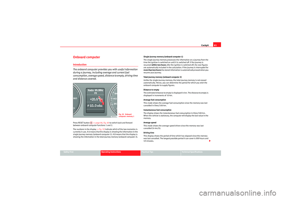
and distance covered.Press RESET button ⇒page 86, fig. 60 to switch back and forward
between onboard computer functions 1 and 2.
The numbers in the display ⇒ fig. 59 indicate which of the two memories is
currently in use. A 1 means that the display is showing the information in the
single journey memory (onboard computer 1). A 2 means that the display is
showing the information in the total journey memory (onboard computer 2). Single-journey memory (onboard computer 1)
The single-journey memory processes the information on a journey from the
time the ignition is switched on until it is switched off. If the journey is
resumed
within two hours after the ignition is switched off, the new figures
are automatically included in the calculation. If the journey is interrupted for
more than two hours t h e s t o r e d i n f o r m a t i o n i s a u t o m a t i ca l l y e r a s e d w h e n y o u
resume your journey.
Total-journey memory (onboard computer 2)
Unlike the single-journey memory, the total-journey memory is not erased
automatically. Hence, you can determine the period for which you wish the
onboard computer to supply figures.
Distance to empty
The estimated distance to empty is displayed in km. The distance to empty is
displayed in increments of 10 km.
Average fuel consumption
This mode shows the average fuel consumption since the memory was last
cancelled in litres/100 km.
Instantaneous fuel consumption
The display shows the instantaneous fuel consumption in litres/100 km.
When the vehicle is stationary, the computer will display the last value in the
memory.
Average speed
This mode shows the average speed driven since the memory was last
cancelled (in km/h).
Driving time
This display shows the period of time which has elapsed since the memory
was last cancelled. The longest possible period it can cover is 999 hours and
59 minutes.
Fig. 59 Onboard
computer: memory 1
AB
exeo_EN.book Seite 85 Montag, 30. August 2010 4:45 16
Page 89 of 319
Cockpit87
Safety First
Operating Instructions
Practical Tips
Technical Specifications
•Journey duration•Distance covered•Average fuel consumption•Average speed
The onboard computer can only be operated when the ignition is switched on.
When the ignition is switched on, the display shows the function that was last
selected.
A s we ll as t h e f i g u r e s f r o m t h e o n b o a r d co m p u te r ( 1 o r 2 ) , t h e d is p la y ca n a l s o
show information from the navigation system*. Press the Reset button
briefly to switch back and forward between these displays.Note
•If you keep the Reset button pressed for longer than two seconds, it will
reset the currently displayed figure to zero (for instance average fuel
consumption).•Faults detected by the auto-check control will be displayed even if the
display is off.•The information in the memory is lost if the battery is disconnected.
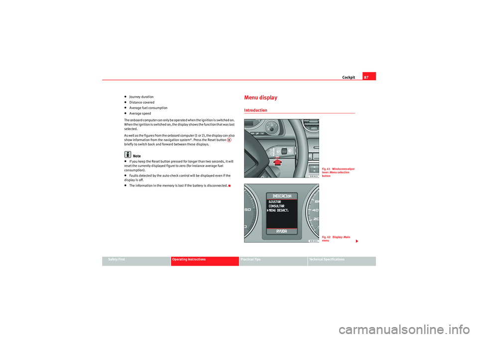
Menu displayIntroduction
AB
Fig. 61 Windscreen wiper
lever: Menu selection
buttonFig. 62 Display: Main
menu
exeo_EN.book Seite 87 Montag, 30. August 2010 4:45 16
Page 90 of 319
Cockpit
88Some of your vehicle’s functions can be adjusted, activated and controlled by
menus . With the aid of the menus you can then also select the information
you wish to see displayed on the DIS display. This is only possible when the
ignition is on. The menu is enabled using the button on the wind-
screen wiper lever ⇒ page 87, fig. 61.
The main menu lists the different display types (or basic commands):
Programming
Check
Menu off
Help
The main menu options have the following submenus:
Controlling the menu
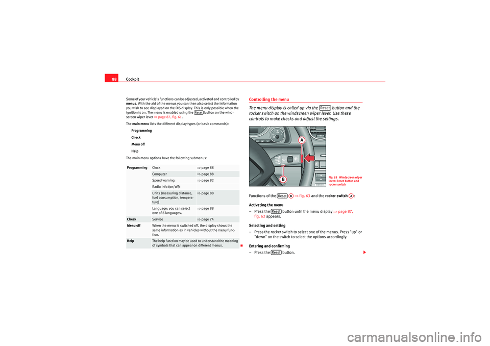
The menu display is called up via the button and the
rocker switch on the windscreen wiper lever. Use these
controls to make checks and adjust the settings.Functions of the ⇒fig. 63 and the rocker switch :
Activating the menu
– Press the button until the menu display ⇒page 87,
fig. 62 appears.
Selecting and setting
– Press the rocker switch to select one of the menus. Press "up" or "down" on the switch to select the options accordingly.
Entering and confirming
–Press the button.
Programming
Clock
⇒ page 88
Computer
⇒page 88
Speed warning
⇒page 82
Radio info (on/off)Units (measuring distance,
fuel consumption, tempera-
ture)
⇒page 88
Language: you can select
one of 6 languages.
⇒page 88
Check
Service
⇒page 74
Menu off
When the menu is switched off, the display shows the
same information as in vehicles without the menu func-
tion.
Help
The help function may be used to understand the meaning
of symbols that can appear on different menus.
Reset
Reset
Fig. 63 Windscreen wiper
lever: Reset button and
rocker switch
Reset
AB
AA
ResetReset
exeo_EN.book Seite 88 Montag, 30. August 2010 4:45 16
Page 99 of 319

Unlocking and locking97
Safety First
Operating Instructions
Practical Tips
Technical Specifications
WARNING
•Always take the key with you when leaving the vehicle, even if you only
intend to be gone for a short time. This is particularly important if there are
children in the vehicle, as they might otherwise be able to start the engine
or use power-operated equipment (e.g. the electric windows), which could
cause injuries.•Wait for the vehicle to come to a standstill before removing the ignition
key from the lock! Otherwise, the steering lock could engage suddenly,
causing an accident.
Indicator light on the remote control key
The condition of the battery in the remote control key is moni-
tored by the indicator light.
Condition of the key battery
The indicator light ⇒fig. 68 (arrow) flashes when one of the buttons is
pressed. If the indicator light does not light up or flash, this means that the
battery is exhausted and must be replaced.
Replacing the batteries ⇒page 97.Replacing the key batteryWe recommend you have the batteries changed in a qualified work-
shop. If you decide to change the used battery yourself, follow the
steps below:
– Carefully prise apart the key ⇒fig. 69 and the cover
using a coin.
– Remove the cover in the direction of the arrow.
Fig. 68 LED on the remote
control key
Fig. 69 Master key:
Opening the cover
AA
AB
exeo_EN.book Seite 97 Montag, 30. August 2010 4:45 16
Page 100 of 319

Unlocking and locking
98
– Remove the used battery from the cover.
– Insert the new battery. Make sure that the “+” symbol on the battery is facing downwards. The co rrect polarity is indicated on
the cover.
– After inserting the battery, align the cover and key and press the two parts together.
For the sake of the environmentUsed batteries must be disposed of at an appropriate waste facility or
through an authorised service, given that their components can affect the
environment.
Note
•The system must be re-synchronised after each battery replacement to be
able to lock and unlock the vehicle using the remote control ⇒page 106.•The new battery must be of the same type as the original.Electronic immobiliser
The electronic immobiliser is designed to prevent unauthor-
ised persons from starting up the vehicle.There is an electronic chip inside the key which automatically deactivates the
immobiliser when the key is inserted into the ignition lock. The electronic
immobiliser is enabled automatically when the ignition key is removed from
the ignition lock after coming to a stop.
If an uncoded key is used, the message SAFE will appear in the trip recorder
display.
Note
•The engine can only be started using an original SEAT key with the correct
code.•It may not be possible to start the engine with the key if there is another
ignition key from a different make of vehicle on the same key tab.Central lockingDescription
The central locking system enables you to lock and unlock all
the doors, the tailgate and the tank flap together.The central locking system on your vehicle locks and unlocks all the doors
and the tank flap simultaneously. The tailgate is unlocked when the vehicle
is opened. However, the handle must be used to open it. The vehicle can be
locked and unlocked using the remote control ⇒ page 104 or by turning the
key in the lock in the driver door.
The windows can also be centrally opened or closed using the central locking
system ⇒page 110. The sunroof* can be closed but not opened using the
central locking system.
The central locking system is combined with an anti-theft security system. If
the vehicle is locked with the key from the outside, the interior opening levers
stop working, which prevents unauthorised persons from entering the
vehicle.
Should the central locking system fail to work, you can activate all the locks
individually.
exeo_EN.book Seite 98 Montag, 30. August 2010 4:45 16
Page 101 of 319
Unlocking and locking99
Safety First
Operating Instructions
Practical Tips
Technical Specifications
Automatic locking function (Auto Lock)*
The
Auto Lock* function automatically locks all doors and the tailgate when
the vehicle exceeds a speed of about 15 km/h.
The vehicle is unlocked again automatically when the ignition key is
removed. Alternatively, the driver can also unlock the vehicle using the
central locking switch
or by opening one of the doors.
WARNING
Do not leave anyone (especially children) in the vehicle if it is locked from
the outside and the anti-theft security system is enabled, as the doors and
windows cannot then be opened from the inside. Locked doors could delay
assistance in an emergency, potentially putting lives at risk.
Note
•Should the central locking system fail to work, you can still lock and
unlock the driver door and the tailgate using the key. Locking the doors
manually if central locking fails to work ⇒page 102.•The anti-theft mechanism and the anti-theft alarm* cannot be enabled if
the central locking is not working.•Never leave any valuable items in the vehicle unattended. Even a locked
vehicle is not a safe.
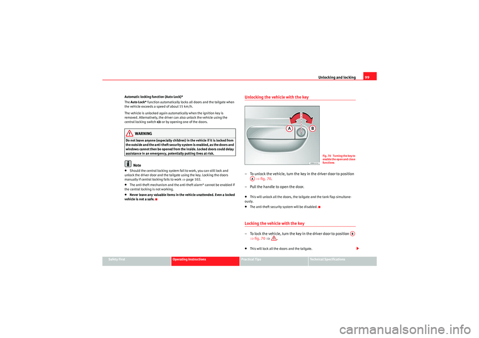
Unlocking the vehicle with the key– To unlock the vehicle, turn the key in the driver door to position ⇒ fig. 70 .
– Pull the handle to open the door.•This will unlock all the doors, the tailgate and the tank flap simultane-
ously.•The anti-theft security system will be disabled.Locking the vehicle with the key– To lock the vehicle, turn the key in the driver door to position ⇒fig. 70 ⇒ .•This will lock all the doors and the tailgate.
Fig. 70 Turning the key to
enable the open and close
functions
AA
AB
exeo_EN.book Seite 99 Montag, 30. August 2010 4:45 16