key Seat Exeo 2010 Owner's Guide
[x] Cancel search | Manufacturer: SEAT, Model Year: 2010, Model line: Exeo, Model: Seat Exeo 2010Pages: 319, PDF Size: 9.64 MB
Page 166 of 319

Air conditioning
164Each of the three buttons has a specific function. The numbers relate to the
air outlets ⇒page 163, fig. 132.
Air directed to windows
This setting directs all the air to outlets 1 and 2. Unlike in setting , the
volume of air delivery remains the same.
Air to the driver/front passenger
All the air comes from outlets 3 and 4 in the dash panel and from the rear of
the centre console.
Air to the footwells
Most of the air emerges from outlets 5 and the outlets under the front seats.
Some of the air will also be issued from outlets 3 and 4.
Note
In all of the above air distribution settings, a small amount of air will still
come from the other outlets.Economical use of the air conditioner
Economical use of the air conditioner will help save fuel.Engine power is reduced and fuel consumption increases when the
air conditioner is in co oling mode. To ensure that the system is only
switched on when it is really necessary, please note the following
points:
– Select ECON mode if you wish to save fuel.
– S e le c t ECO N m o d e i f yo u d e ci d e t o o p e n t h e w i n d o w s o r su n r o o f * while driving. – If the vehicle has heated up after standing in the sun, open the
windows and doors for a short time to cool the vehicle.
For the sake of the environment
By saving fuel you also reduce the amount of pollutants emitted from your
vehicle.Key settings
When the ignition is switched on, the air conditioner settings
assigned to the key are selected automatically.The air conditioner settings selected are automatically stored and assigned
to the key in use. When the vehicle is started, the air conditioner automati-
cally selects the settings assigned to the key. Hence, every driver automati-
cally obtains his/her preferred settings without having to select them manu-
ally.
Note
Should another driver use the key and enter other settings, the previous
settings will be deleted.
�<
exeo_EN.book Seite 164 Montag, 30. August 2010 4:45 16
Page 169 of 319
Driving167
Safety First
Operating Instructions
Practical Tips
Technical Specifications
The Electronic Stability Programme (ESP) contains the electronic differential
lock (EDL) and the traction control system (TCS). The ESP function works
together with the ABS. If a fault in the ABS occurs, both warning lamps light
up, but if the ESP fails, only the ESP warning lamp lights up.
The ESP is started automatically when the engine is started.
The ESP switch deactivates both TCS and ESP functions. The ESP, in spite of
being deactivated, will always self-connect when necessary if brakes are
being used.
The TCS can be deactivated when in cases where wheel sliding is desirable.
For example:
•When driving with snow chains,•when driving in deep snow or on loose surfaces,•when rocking the vehicle backwards and forwards to free it from mud, for
example.
Next, the button should be pressed to reactivate the TCS.
When does the warning lamp switch on or flash?•On switching the ignition on, it lights up for about two seconds to carry
out a function control.•The warning lamp will start flashing when the vehicle is moving if the ESP
or the TCS is activated.•It will light up continuously if there is a malfunction in the ESP.WARNING
•The Electronic Stability Programme (ESP) cannot defy the laws of
physics. This should be kept in mind, particularly on slippery and wet
roads and when towing a trailer.•Always adapt your driving style to suit the condition of the roads and
the traffic situation. Do not let the extra safety afforded by ESP tempt you
into taking any risks when driving, as this can cause accidents.
•Please refer to the corresponding warning notes on ESP in ⇒page 185,
“Intelligent technology”.
Ignition lockIgnition key positions
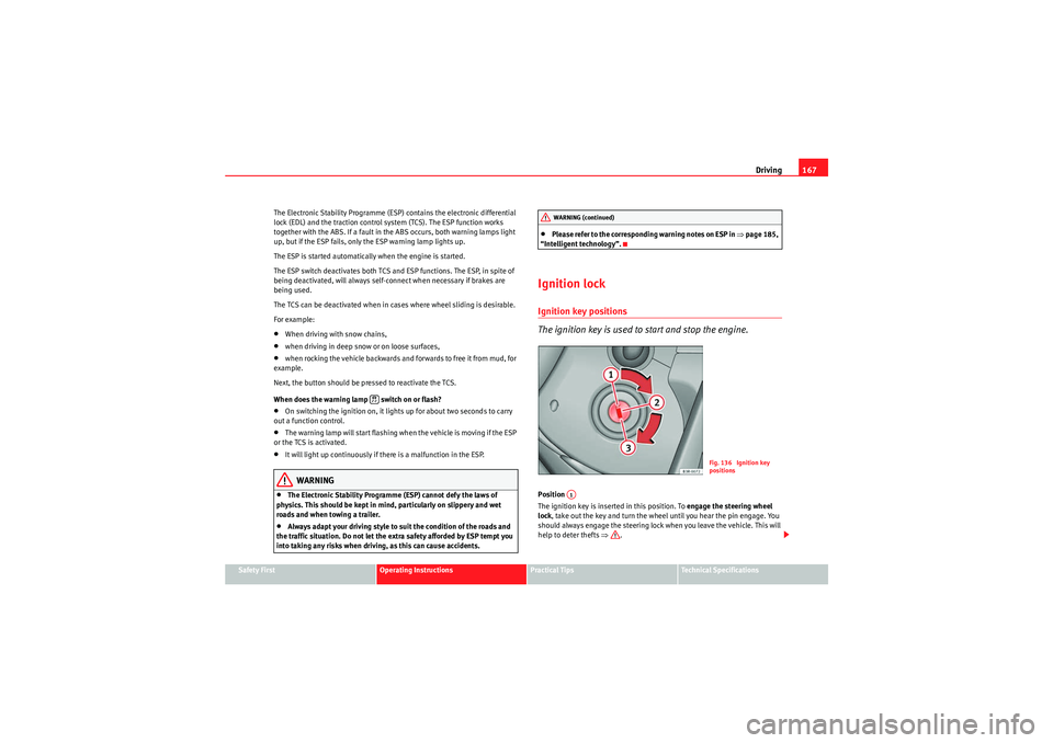
The ignition key is used to start and stop the engine.Position
The ignition key is inserted in this position. To engage the steering wheel
lock , take out the key and turn the wheel until you hear the pin engage. You
should always engage the steering lock when you leave the vehicle. This will
help to deter thefts ⇒.
WARNING (continued)
Fig. 136 Ignition key
positions
A1
exeo_EN.book Seite 167 Montag, 30. August 2010 4:45 16
Page 170 of 319
Driving
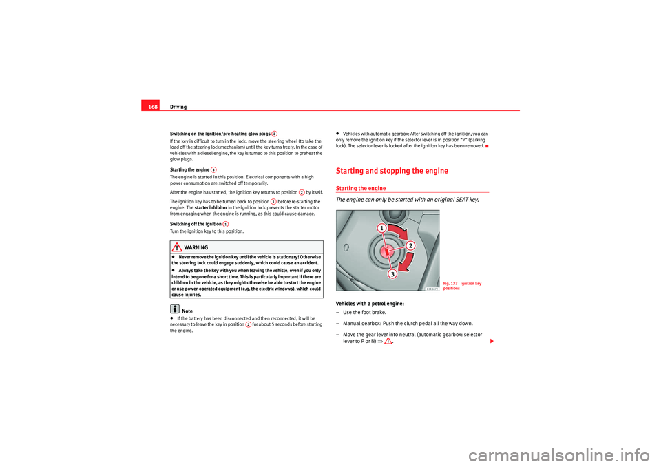
168Switching on the ignition/pre-heating glow plugs
If the key is difficult to turn in the lock, move the steering wheel (to take the
load off the steering lock mechanism) until the key turns freely. In the case of
vehicles with a diesel engine, the key is turned to this position to preheat the
glow plugs.
Starting the engine
The engine is started in this position. Electrical components with a high
power consumption are switched off temporarily.
After the engine has started, the ignition key returns to position by itself.
The ignition key has to be turned back to position before re-starting the
engine. The starter inhibitor in the ignition lock prevents the starter motor
from engaging when the engine is running, as this could cause damage.
Switching off the ignition
Turn the ignition key to this position.
WARNING
•Never remove the ignition key until the vehicle is stationary! Otherwise
the steering lock could engage suddenly, which could cause an accident.•Always take the key with you when leaving the vehicle, even if you only
intend to be gone for a short time. This is particularly important if there are
children in the vehicle, as they might otherwise be able to start the engine
or use power-operated equipment (e.g. the electric windows), which could
cause injuries.Note
•If the battery has been disconnected and then reconnected, it will be
necessary to leave the key in position for about 5 seconds before starting
the engine.
•Vehicles with automatic gearbox: After switching off the ignition, you can
only remove the ignition key if the selector lever is in position “P” (parking
lock). The selector lever is locked after the ignition key has been removed.Starting and stopping the engineStarting the engine
The engine can only be started with an original SEAT key.Vehicles with a petrol engine:
– Use the foot brake.
– Manual gearbox: Push the clutch pedal all the way down.
– Move the gear lever into neutral (automatic gearbox: selector lever to P or N) ⇒.
A2
A3
A2
A1
A1
A2
Fig. 137 Ignition key
positions
exeo_EN.book Seite 168 Montag, 30. August 2010 4:45 16
Page 171 of 319
Driving169
Safety First
Operating Instructions
Practical Tips
Technical Specifications
– Turn the ignition key to position without pressing the acceler-
ator.
– Release the ignition key as soon as the engine starts (the starter motor must not be allowed to run on with the engine).
Vehicles with a diesel engine:
– Use the foot brake.
– Manual gearbox: Push the clutch pedal all the way down.
– Move the gear lever into neutral (automatic gearbox: selector lever to P or N) ⇒.
– Turn the ignition key to position . The pre-heating indicator light
�D comes on while the glow plugs are preheating.
– When the indicator light
�D goes out, turn the ignition key to
position . Do not press the accelerator.
– Release the ignition key as soon as the engine starts (the starter motor must not be allowed to run on with the engine).
When starting a very cold engine, it may be a little noisy for the first few
seconds until oil pressure has built up in the hydraulic valve compensators.
This is quite normal, and no cause for concern.
If the engine fails to start straight away, stop after 10 seconds and try again
after about half a minute.
Glow plug system*
To assist starting at low temperatures, diesel engines are equipped with a
glow plug preheating system. The preheating time depends on the coolant
temperature and the outside temperature. Start the engine as soon as the
glow plug indicator light
�D goes out. When the engine is warm or at outside temperatures above +8°C, the glow
plug indicator light will only come on for about one second. This means that
the engine can be started
immediately.
If the engine will not start...
•⇒ page 284•⇒page 287•⇒page 220, “Refuelling”WARNING
Never run the engine in confined spaces, as the exhaust gases are
poisonous.
Caution
Avoid high engine speeds, full throttle and extreme load conditions until the
engine has reached its normal operating temperature, otherwise this can
damage the engine.
For the sake of the environment
Do not warm up the engine by running the engine with the vehicle stationary.
Start immediately. This will help avoid unnecessary exhaust emissions.Stopping the engine– Turn the ignition key to position ⇒page 168, fig. 137 .
WARNING
•Never switch the engine off until the vehicle is stationary.
A3A2
A3
A1
exeo_EN.book Seite 169 Montag, 30. August 2010 4:45 16
Page 183 of 319

Driving181
Safety First
Operating Instructions
Practical Tips
Technical Specifications
Selector lever lock
The selector lever lock prevents gears from being engaged
inadvertently, so that the vehicle is not set in motion uninten-
tionally.The selector lever lock is released as follows:
– Switch the ignition on.
–Press the brake pedal and at the same time press in the interlock
button.Automatic selector lever lock
With the ignition turned on, the selector lever is locked in the positions P and
N. To remove it from these positions, press on the brake. The following
message appears in the instrument panel as a reminder for the driver when
the selector lever is in position P or N:
WHEN STATIONARY APPLY FOOTBRAKE WHILE SELECTING GEAR The selector lever lock only works if the vehicle is stationary or driving at
speeds up to 5 km/h. At higher speeds the selector lever lock in the N posi-
tion is disengaged automatically.
The selector lever lock is not engaged if the selector lever is moved quickly
through position N (e.g. when shifting from R to D). This makes it possible, for
instance, to “rock” the vehicle backwards and forwards if it is stuck in snow
or mud. The selector lever lock engages automatically if the brake pedal is not
depressed and the lever is in position N for more than about a second.
Interlock button
The interlock button on the selector lever handle prevents the driver from
inadvertently engaging particular gears. Press the button in to disengage the
selector lever lock. The selector lever
positions in which the interlock button
has to be pressed are shown in the illustration, highlighted in colour
⇒ fig. 145 .
Safety interlock for ignition key
Once the ignition has been turned off, the key may be removed only if the gear
selector is in position P. While the key is not in the ignition, the selector lever
is locked in position P.
Kick-down feature
The kickdown feature is designed to give maximum accelera-
tion.Vehicles with multitronic
® gearbox
When the accelerator pedal is pressed right down past the point of resistance
at full throttle, the gearbox will select a lower gear ratio, depending on road
speed and engine speed. While you keep the accelerator depressed the
engine speed is automatically controlled to give your vehicle maximum accel-
eration.
Fig. 145 Selector lever
lock functions
exeo_EN.book Seite 181 Montag, 30. August 2010 4:45 16
Page 201 of 319

Trailer towing199
Safety First
Operating Instructions
Practical Tips
Technical Specifications
Where possible, operate the trailer with the maximum permitted
drawbar
load on the ball joint of the towing bracket, but do not exceed the specified
limit.
Tyre pressure
Check the tyre pressures on your vehicle, and adjust for “full load” conditions
(refer to the sticker listing the tyre pressures on the door pillar). It may also be
necessary to adjust the tyre pressures on the trailer according to the recom-
mendations of the trailer manufacturer.
Exterior mirrors
Check whether you can see enough of the road behind the trailer with the
standard mirrors. If this is not the case you should have additional mirrors
fitted. The two exterior mirrors should be fitted on folding arms. Adjust the
mirrors to give sufficient rear vision.
Headlights
Before starting a journey, check the headlight beam settings with the trailer
hitched up. If necessary, alter the height of the headlight beams by means of
the headlight range control. See ⇒page 119.
Power supply
When you remove the ignition key, the power supply to the trailer is inter-
rupted.
Removable ball joint coupling
Vehicles with a factory-fitted towing bracket are equipped with a removable
ball joint coupling. This is stored in the spare wheel well in the luggage
compartment together with the necessary fitting instructions.
Note
If you frequently tow, we recommend you also have the vehicle serviced
between services.
Notes on towing
Towing a trailer involves additional attention by the driver.Weight distribution
The weight distribution of a loaded trailer with an unladen vehicle is very
unfavourable. However, if this cannot be avoided, drive extra slow to allow for
the unbalanced weight distribution.
Speed
The stability of the vehicle and trailer is reduced with increasing speed. There-
fore, it is advisable not to drive at the maximum permissible speed in unfa-
vourable road, weather or wind condit ions. This especially applies when
driving downhill.
You should always reduce speed immediately if the trailer shows the slightest
sign of swaying . Never try to stabilise the trailer by accelerating.
Anticipate hazards and brake in good time. If towing a trailer with an inertia
brake , first brake gently and then harder. This will prevent brake tapping by
the trailer wheels when they lock. Select a low gear in due course before
going down a steep downhill. This enables you to use the engine braking to
slow down the vehicle.
Swaying and pitching can be reduced by stabiliser aids. We recommend
having stabiliser aids installed when towing trailers with a high trailer weight.
They can be purchased and installed at a Technical Service.
Reheating
When climbing long hills in hot weather with the engine running fast in low
gear, you should keep an eye on the coolant temperature gauge ⇒page 60.
Reduce speed immediately if the needle moves to the right end of the scale.
If the temperature warning lamp
�v in the instrument panel should start
flashing, stop the vehicle and let the engine cool down by running it at idling
speed for a few minutes.
exeo_EN.book Seite 199 Montag, 30. August 2010 4:45 16
Page 206 of 319
Trailer towing
204
Setting the spring mechanism to the ready position (if required)
– Insert the key ⇒page 203, fig. 155 in the lock on the knob
and turn it towards the red marking.
– Pull out the knob in direction , hold and turn in direction
until the locking pin engages and the release pin moves
out visibly ⇒.
Inserting the ball joint
– With the spring mechanism in the ready position, insert the ball joint into the mounting fixture and push it upwards ⇒page 203,
fig. 156 in the direction indicated (arrow) ⇒. It should lock
into position automatically. You should now clearly hear it click
into place.
– Lock the ball joint by turning the key to the green marking.
– Remove the key.Cont ⇒page 204, “Fitting the ball joint (step 4)”.
WARNING
•If it is not possible to set the spring mechanism to the ready position as
described above, do not use the ball joint. Please contact a qualified work-
shop.•To avoid injury, keep your hands away from the knob or cover piece
when inserting the ball joint in the mounting fixture. Otherwise, you could
be injured.
Fitting the ball joint (step 4)
A1
AA
AB
A2
A3
Fig. 157 Removable
towing bracket: Safety
checkFig. 158 Rear bumper:
Pulling down the power
socket
exeo_EN.book Seite 204 Montag, 30. August 2010 4:45 16
Page 207 of 319
Trailer towing205
Safety First
Operating Instructions
Practical Tips
Technical Specifications
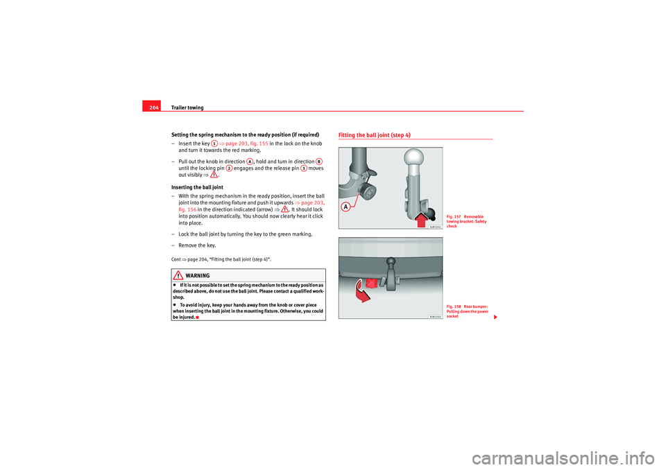
Safety check
– Check that the green marking ⇒page 204, fig. 157 on the
knob is inside the black zone marked on the ball joint.
– Check that the knob is directly against the ball joint, so that there is no gap between the knob and the ball joint -arrow-.
– Check that the ball joint is locked and the key is removed so that the knob cannot be pulled out ⇒.
– Check that the ball joint fits tightly in the mounting fixture (try moving it about to check).
To w i n g s o c k e t
– To plug in the electrical connection for the trailer, pull down the socket below the bumper ⇒page 204, fig. 158 .If the safety check is not satisfactory, the ball joint must be fitted again prop-
erly.
WARNING
To avoid accidents, the ball joint must meet all the safety requirements
listed in the safety check. The towing bracket must not be used if any one
of these requirements is not met. If this is the case, you should contact a
qualified workshop.
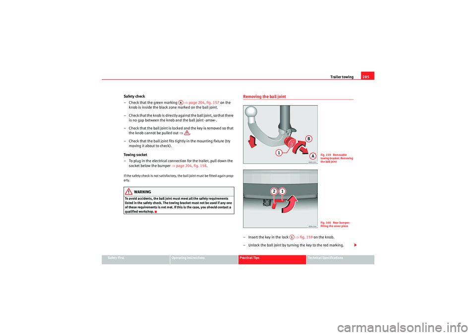
Removing the ball joint– Insert the key in the lock ⇒fig. 159 on the knob.
– Unlock the ball joint by turning the key to the red marking.
AA
Fig. 159 Removable
towing bracket: Removing
the ball jointFig. 160 Rear bumper:
fitting the cover piece
A1
exeo_EN.book Seite 205 Montag, 30. August 2010 4:45 16
Page 211 of 319
Vehicle maintenance and cleaning209
Safety First
Operating Instructions
Practical Tips
Technical Specifications
Vehicle maintenance and cleaningGeneral notesRegular washing and care help maintain the value of your
vehicle.Vehicle maintenance
Regular care and washing help to maintain the value of the vehicle. This may
also be one of the requirements for acknowledging warranty claims in the
event of bodywork corrosion or paint defects.
The best way to protect your vehicle against the harmful effects of the envi-
ronment is through correct maintenance and frequent washing. The longer
substances such as insect remains, bird droppings, resinous tree sap, road
dirt, industrial deposits, tar, soot or road salt and other aggressive materials
remain on the vehicle, the more damage they do to the paintwork. High
temperatures (for instance in strong sunlight) further intensify the corrosive
effect.
After winter, a period when salt is put on the roads, it is impor tant to have the
underside of the vehicle washed thoroughly.
Products for vehicle maintenance
Car care products are available in your Authorised Service Centre. Keep the
product instructions until you have used them up.
WARNING
•Car care products can be toxic. Because of this, they must always be
kept closed in their original container. Keep them out of the reach of chil-
dren. Failure to comply could result in poisoning.•Always read and observe the instructions and warnings on the package
before using vehicle care products. Im proper use could cause health prob- lems or damage the vehicle. The use of certain products may produce
noxious vapours; they should be used in well ventilated areas.
•Never use fuel, turpentine, engine oil, nail varnish remover or other
volatile fluids. These are toxic and highly flammable. Risk of fire and explo-
sion.•Before washing your vehicle, or carrying out any maintenance, switch
the engine off, apply the handbrake firmly and remove the key from the
ignition.Caution
Never attempt to remove dirt, mud or dust if the surface of the vehicle is dry.
Never use a dry cloth or sponge for cleaning purposes. This could damage the
paintwork or the windows of your vehicle. Soak dirt, mud or dust with plenty
of water.
For the sake of the environment
•When purchasing products for your vehicle maintenance, select the ones
which are not harmful to the environment.•The waste from car care products should not be disposed of with ordinar y
household waste. Observe the disposal information on the package.WARNING (continued)
exeo_EN.book Seite 209 Montag, 30. August 2010 4:45 16
Page 217 of 319
Vehicle maintenance and cleaning215
Safety First
Operating Instructions
Practical Tips
Technical Specifications
Cleaning the engine compartment
Take special care when cleaning the engine compartment.Anti-corrosion treatment
The engine compartment and the surface of the power unit are given anti-
corrosion treatment at the factory.
Good corrosion protection is particularly important in winter when the vehicle
is frequently driven on salted roads. To prevent the salt corroding the vehicle,
the entire engine compartment should be thoroughly cleaned before and
after winter.
Yo u r A u t h o r i s e d S e r v i ce Ce n t re has got the necessary equipment to provide
the correct cleaning and preserving products. For this reason, we recommend
having this work performed by them.
The anti-corrosion protection is usually removed if the engine compartment
is cleaned with grease removing solutions, or if you have the engine cleaned.
On commissioning this work, ensure that all surfaces, seams, joints and
components in the engine compartment are given anti-corrosion treatment.
WARNING
•When working in the engine compartment, always observe the safety
warnings ⇒page 224.•Before opening the bonnet, switch the engine off, apply the handbrake
firmly and always remove the key from the ignition.•Allow the engine to cool before you clean the engine compartment.•Do not clean the vehicle underbody, wheel arches or wheel trims
without protecting your hands and arms. You may cut yourself on sharp-
edged metal parts. Failure to comply could result in injury.•Moisture, ice and salt on the brakes may affect braking efficiency. Risk
of accident. Directly after washing, avoid sudden and sharp braking.
•Never touch the radiator fan. It is temperature-controlled and could
start automatically, even when the key is removed from the ignition!For the sake of the environment
Fuel, grease and oil deposits could be removed when the engine is washed.
The polluted water must be cleaned in an oil separator. For this reason,
engine washing should be carried out only by a qualified workshop or a petrol
station.Vehicle interior maintenancePlastic parts and dash panel cleaning– Use a clean, damp cloth to clean plastic parts and the dash panel.
– If this does not provide satisfactory results, use a special solvent-free plastic cleaning product.
WARNING
Never clean the dash panel and the airbag module surface with cleaners
containing solvents. Solvents cause the surface to become porous. If the
airbag triggered, plastic parts could become detached and cause injuries.
Caution
Cleaning products which contain solvents will damage the material.
WARNING (continued)
exeo_EN.book Seite 215 Montag, 30. August 2010 4:45 16