reset Seat Exeo 2011 Owner's manual
[x] Cancel search | Manufacturer: SEAT, Model Year: 2011, Model line: Exeo, Model: Seat Exeo 2011Pages: 313, PDF Size: 5.02 MB
Page 62 of 313
60Cockpit
CHECK button . . . . . . . . . . . . . . . . . . . . . . . . . . . . . . . . . . . . . . . . . . . . . 64
Call-up button for service indicator . . . . . . . . . . . . . . . . . . . . . . . . .74
Reset button for trip recorder . . . . . . . . . . . . . . . . . . . . . . . . . . . . . . 63
Coolant temperature gauge
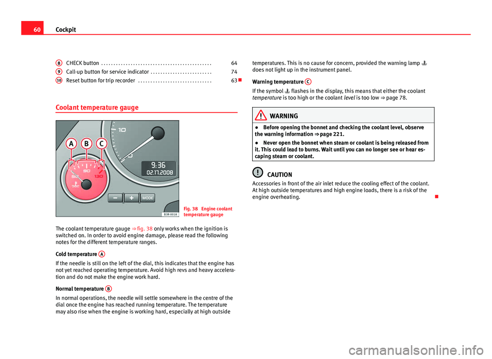
Fig. 38 Engine coolant
temperature gauge
The coolant temperature gauge ⇒ fig. 38 only works when the ignition is
switched on. In order to avoid engine damage, please read the following
notes for the different temperature ranges.
Cold temperature A
If the needle is still on the left of the dial, this indicates that the engine has
not yet reached operating temperature. Avoid high revs and heavy accelera-
tion and do not make the engine work hard.
Normal temperature B
In normal operations, the needle will settle somewhere in the centre of the
dial once the engine has reached running temperature. The temperature
may also rise when the engine is working hard, especially at high outside8
910
temperatures. This is no cause for concern, provided the warning lamp
does not light up in the instrument panel.
Warning temperature C
If the symbol
flashes in the display, this means that either the coolant
temperature is too high or the coolant level is too low ⇒ page 78.
WARNING
● Before opening the bonnet and checking the coolant level, observe
the warning information ⇒ page 221.
● Never open the bonnet when steam or coolant is being released from
it. This could lead to burns. Wait until you can no longer see or hear es-
caping steam or coolant.
CAUTION
Accessories in front of the air inlet reduce the cooling effect of the coolant.
At high outside temperatures and high engine loads, there is a risk of the
engine overheating.
Page 65 of 313

63
Cockpit
Speedometer with odometer
The speedometer indicates the speed of the vehicle and the
distance travelled.
Fig. 42 Detailed view of
the instrument panel:
Odometer
The distance is normally stated in kilometres (km). On some models, how-
ever, the odometer will show “miles”.
Lower odometer
The lower odometer records the vehicle's total mileage.
Upper odometer (trip recorder)
The upper odometer shows the distance that has been travelled since the
trip recorder was last reset. It is used to measure short trips. The last digit of
the trip recorder indicates distances of 100 metres or tenths of a mile. The
upper odometer can be reset to zero by pressing the reset button ⇒ fig. 42.
Fault display
If there is a fault in the instrument panel, the letters DEF will appear perma-
nently in the trip recorder display. Please have the fault repaired as soon as
possible. Electronic immobiliser
The vehicle key data is consulted when the ignition is switched on.
If an uncoded key is used, the message
SAFE will appear in the trip recorder
display. The vehicle can no longer be started if that happens.
Fuel reserve
The display only works when the ignition is switched on.
When the needle reaches the reserve zone, the symbol lights up in the
instrument panel display ⇒ page 80. At this point there are still about 8 to
10 litres of fuel left in the tank. This is your reminder to fill up soon.
You can consult the tank capacity of your vehicle in the ⇒ page 299, Di-
mensions and capacities section.
CAUTION
Never run the tank completely dry. If there is an irregular fuel supply, misfir-
ing can occur. This means that fuel could reach the exhaust system without
burning. This may lead to the catalytic converter reheating and being dam-
aged.
Safety FirstOperating InstructionsPractical TipsTechnical Specifications
Page 77 of 313
75
Cockpit
Service reminder
The instrument panel controls the distance travelled every day. It calculates
the average of these distances travelled and activates the service reminder
sufficiently in advance.
The display reverts back to the standard display after about 5 seconds. The
remaining distance to the next service is updated every time the ignition is
switched on, until the service becomes due.
Service due
When a service is due, SERVICE! will appear in the display immediately after
you switch on the ignition. The display reverts back to the standard display
after about 5 seconds.
Resetting the display
The display is reset by the workshop after the service has been carried out.
The service interval will be set to a LongLife Service (flexible service inter-
val) or Inspection Service (fixed service interval), depending on which en-
gine oil is used. It is only possible to reset the display via the instrument
panel when an oil change is performed; in this case the display can only be
reset to a fixed service interval of 15 000 km. Proceed as follows:
● Switch the ignition off.
● Press the service button ⇒ fig. 52 1
and hold while switching on the
ignition. The display will show one of these messages: Service in ----- km or
Service!
● Now press and hold the reset button 2
until the display shows
Service
in ----- km --- days or Service!
The display switches out of the reset mode if you do not press the reset but-
ton within 5 seconds.
CAUTION
The system cannot calculate the figures for the service interval display if the
battery is disconnected from the vehicle, so no service reminder can be dis-
played during this time. Please remember that it is essential to service the
vehicle within the established time limits to prevent its deterioration and to
extend its useful life (particularly that of the engine). The period between
two services must never be longer than the time specified in the Mainte-
nance Programme, even if you only cover a low mileage during this time.
Note
● Do not reset the service indicator between services, otherwise the dis-
play will be incorrect.
● The information in the service indicator remains intact if the battery is
disconnected.
● The distance to the next service cannot be called up if the system has
detected a Priority 1 fault (red symbol).
Auto-check system Introduction
The auto-check system checks important components and vehicle systems.
These background checks are run constantly, as long as the ignition is
switched on.
A message is displayed on the instrument panel if a fault should occur or if
any maintenance or repairs are urgently required. This is accompanied by
an audible warning signal. Depending on the priority of the fault, a red or
yellow warning symbol lights up on the display.
Safety FirstOperating InstructionsPractical TipsTechnical Specifications
Page 86 of 313
84Cockpit
–Press the CHECK button for at least two seconds.
The speed warning symbol lights up briefly in the display when the but-
ton is released to confirm that the selected speed has been stored. The
speed limit that has been selected remains stored until another speed is se-
lected with a brief push of the button, or until the memory is cleared with a
long push of the button.
Setting speed limit warning 2
Speed limit warning 2 is set using the switches on the wind-
screen wiper lever.
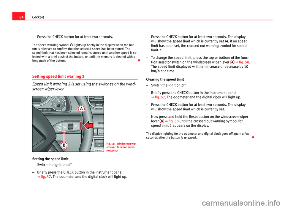
Fig. 58 Windscreen wip-
er lever: Function selec-
tor switch
Setting the speed limit
– Switch the ignition off.
– Briefly press the CHECK button in the instrument panel
⇒ fig. 57. The odometer and the digital clock will light up. –
Press the CHECK button for at least two seconds. The display
will show the speed limit which is currently set or, if no speed
limit has been set, the crossed out warning symbol for speed
limit 2.
– To change the speed limit, press the top or bottom of the func-
tion selector switch on the windscreen wiper lever A
⇒ fig. 58.
The speed limit displayed will then increase or decrease by 10
km/h at a time.
Clearing the speed limit
– Switch the ignition off.
– Briefly press the CHECK button in the instrument panel
⇒ fig. 57. The odometer and the digital clock will light up.
– Press the CHECK button for at least two seconds. The display
will show the speed limit which is currently set.
– Now press and hold the Reset button on the windscreen wiper
lever B
⇒ fig. 58 until the crossed out warning symbol for
speed limit 2 appears on the display.
The display lighting for the odometer and digital clock goes off again a few
seconds after the button is released.
Page 87 of 313

85
Cockpit
Onboard computer Introduction
The onboard computer provides you with useful information
during a journey, including average and current fuel con-
sumption, average speed, distance to empty, driving time
and distance covered.
Fig. 59 Onboard com-
puter: memory 1
Press RESET button B
⇒ fig. 60 to switch back and forward between on-
board computer functions 1 and 2.
The numbers in the display ⇒ fig. 59 indicate which of the two memories is
currently in use. A 1 means that the display is showing the information in
the single journey memory (onboard computer 1). A 2 means that the dis-
play is showing the information in the total journey memory (onboard com-
puter 2). Single-journey memory (onboard computer 1)
The single-journey memory processes the information on a journey from the
time the ignition is switched on until it is switched off. If the journey is re-
sumed within two hours after the ignition is switched off, the new figures
are automatically included in the calculation. If the journey is interrupted for
more than two hours the stored information is automatically erased when
you resume your journey.
Total-journey memory (onboard computer 2)
Unlike the single-journey memory, the total-journey memory is not erased
automatically. Hence, you can determine the period for which you wish the
onboard computer to supply figures.
Distance to empty
The estimated distance to empty is displayed in km. The distance to empty
is displayed in increments of 10 km.
Average fuel consumption
This mode shows the average fuel consumption since the memory was last
cancelled in litres/100 km.
Instantaneous fuel consumption
The display shows the instantaneous fuel consumption in litres/100 km.
When the vehicle is stationary, the computer will display the last value in
the memory.
Average speed
This mode shows the average speed driven since the memory was last can-
celled (in km/h).
Driving time
This display shows the period of time which has elapsed since the memory
was last cancelled. The longest possible period it can cover is 999 hours
and 59 minutes.
Safety FirstOperating InstructionsPractical TipsTechnical Specifications
Page 88 of 313

86Cockpit
Driving time warning
After 2 hours of continuous driving, the display automatically switches over
to the driving time display of 2:00. At the same time the driving time display
starts flashing. This is to remind the driver to take a break.
The driving time warning can be switched off by briefly pressing the func-
tion selector switch or the Reset
button ⇒ fig. 60.
If you continue driving or take a break for less than 10 minutes, the driving
time warning will switch on once again when the total driving time is 4:00
hours, 6:00 hours, etc. However, if you take a break for more than 10 mi- nutes, the driving time warning clock will be erased.
Distance covered
This display shows the distance you have covered since the memory was
last cancelled. The longest possible distance which can be recorded is
9999.9 km.
Note
● The displays for fuel consumption (average and instantaneous), dis-
tance to empty and speed are shown in metric units.
● The information in the memory is lost if the battery is disconnected. Operation
The onboard computer is controlled by means of two
switches on the windscreen wiper lever.
Fig. 60 Windscreen wip-
er lever: Onboard com-
puter controls
Activating the onboard computer
– Press the reset button B
repeatedly until the onboard comput-
er (memory 1 or 2) ⇒ fig. 59 is displayed.
Selecting the function
– Press the top or bottom of the function selector switch A
⇒ fig. 60. This displays the functions of the onboard computer
in sequence.
Resetting to zero
– Press and hold the Reset button B
for at least two seconds.
The following values can be reset to zero using the Reset button:
Page 89 of 313

87
Cockpit
● Journey duration
● Distance covered
● Average fuel consumption
● Average speed
The onboard computer can only be operated when the ignition is switched
on. When the ignition is switched on, the display shows the function that
was last selected.
As well as the figures from the onboard computer (1 or 2), the display can
also show information from the navigation system*. Press the Reset button B
briefly to switch back and forward between these displays.
Note
● If you keep the Reset button pressed for longer than two seconds, it will
reset the currently displayed figure to zero (for instance average fuel con-
sumption).
● Faults detected by the auto-check control will be displayed even if the
display is off.
● The information in the memory is lost if the battery is disconnected.
Safety FirstOperating InstructionsPractical TipsTechnical Specifications
Page 90 of 313
88Cockpit
Menu display
Introduction
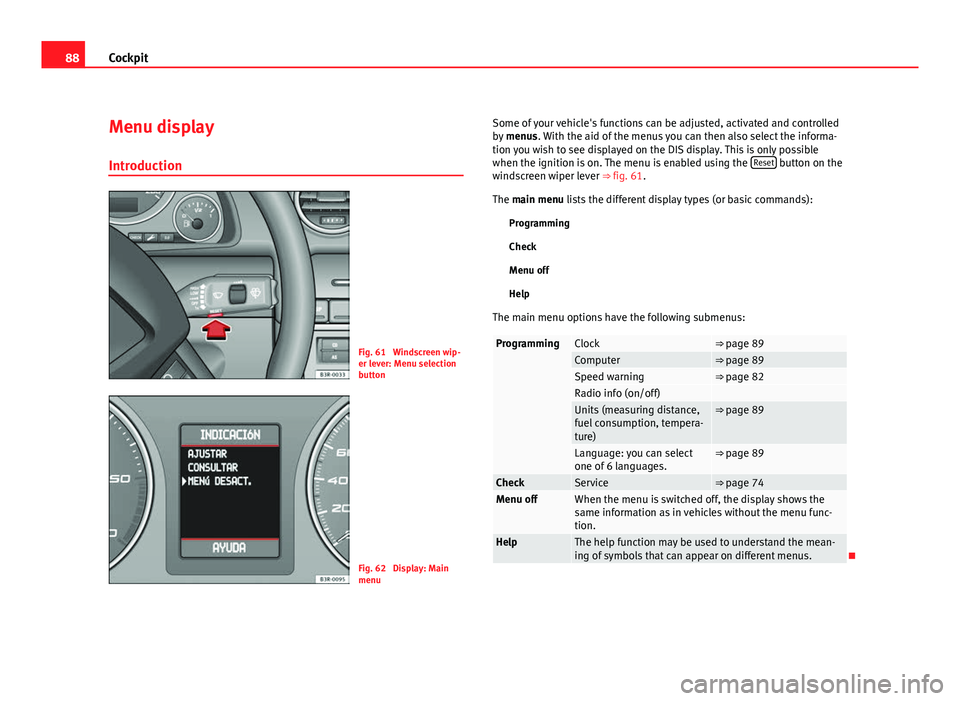
Fig. 61 Windscreen wip-
er lever: Menu selection
button
Fig. 62 Display: Main
menu Some of your vehicle's functions can be adjusted, activated and controlled
by
menus. With the aid of the menus you can then also select the informa-
tion you wish to see displayed on the DIS display. This is only possible
when the ignition is on. The menu is enabled using the Reset
button on the
windscreen wiper lever ⇒ fig. 61.
The main menu lists the different display types (or basic commands):
Programming
Check
Menu off
Help
The main menu options have the following submenus:
ProgrammingClock⇒ page 89Computer⇒ page 89Speed warning⇒ page 82Radio info (on/off) Units (measuring distance,
fuel consumption, tempera-
ture)⇒ page 89
Language: you can select
one of 6 languages.⇒ page 89
CheckService⇒ page 74Menu offWhen the menu is switched off, the display shows the
same information as in vehicles without the menu func-
tion.
HelpThe help function may be used to understand the mean-
ing of symbols that can appear on different menus.
Page 91 of 313
89
Cockpit
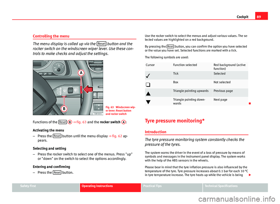
Controlling the menu
The menu display is called up via the Reset button and the
rocker switch on the windscreen wiper lever. Use these con-
trols to make checks and adjust the settings.
Fig. 63 Windscreen wip-
er lever: Reset button
and rocker switch
Functions of the Reset
B ⇒
fig. 63 and the rocker switch A:
Activating the menu
– Press the Reset
button until the menu display
⇒ fig. 62 ap-
pears.
Selecting and setting
– Press the rocker switch to select one of the menus. Press "up"
or "down" on the switch to select the options accordingly.
Entering and confirming
– Press the Reset
button. Use the rocker switch to select the menus and adjust various values. The se-
lected values are highlighted on a red background.
By pressing the
Reset
button, you can confirm the option you have selected
or the value you have set. Selected functions are marked with a tick.
The following symbols are used:
CursorFunction selectedRed background (active
function)
TickSelected
BoxNot selected
Triangle pointing upwardsPrevious page
Triangle pointing down-
wardsNext page
Tyre pressure monitoring* Introduction
The tyre pressure monitoring system constantly checks the
pressure of the tyres.
The system warns the driver in the event of a loss of pressure by means of
symbols and messages in the instrument panel display. The system works
with the help of the ABS sensors in the wheels.
Please bear in mind that the tyre inflation pressure is also influenced by the
temperature of the tyre. Tyre pressure increases about 0.1 bar for each 10 °C
in tyre temperature increase. The tyre heats up while the vehicle is being
Safety FirstOperating InstructionsPractical TipsTechnical Specifications
Page 118 of 313

116Lights and visibility
Automatic headlight switch* (sensor-controlled)
If you set the light switch to “AUTO”, the dipped headlights
will switch on and off automatically according to the ambi-
ent light level.
Fig. 85 Detailed view of
the dash panel: Light
switch
Turning on dipped beam headlights
– Turn the light switch ⇒ fig. 85 to the AUTO position.
Turning off dipped beam headlights
– Turn the light switch to position O.
The symbol on the switch lights up when the switch is in the AUTO position.
The dipped beams, side lights, tail lights and number plate lights come on
together when the headlights are switched on automatically.
When you are using the automatic headlights switch, you can also operate
the main beam headlights, however, please note the following: If you ena-
ble the main beam headlights while using the automatic headlights func- tion during the day (e.g. when driving through a tunnel), but do not disable
them again, only the dipped beam headlights will come on the next time
the lights are automatically switched on. To be able to use the main beam
headlights again, you must first pull the main beam lever back to the "off"
position and then push it forward again to "on".
The side lights, headlights, fog lights and rear fog light can still be switched
on manually in the normal way by using lights switch
⇒ page 115.
The interior mirror is fitted with sensors that measure the ambient light. The
dipped beam headlights will be switched on automatically if the available
light drops below the factory preset value (for instance when driving
through a tunnel, etc.). The headlights switch off again automatically when
the light level increases ⇒
.
WARNING
● The automatic dipped beam headlights are only intended to assist
the driver. Automatic dipped beam headlights do not relieve the driver of
his or her responsibility to control them and turn off or turn on the lights
manually according to weather or lighting conditions. The light sensors
are, for example, unable to detect rain and fog - you should therefore al-
ways switch on the dipped beam headlights manually in these condi-
tions and when driving after dark.
● Observe all relevant legal requirements when using the signalling
and lighting systems described here.
Note
● If automatic headlight switching is activated, when the ignition is turned
off the dipped beam headlights are turned off, and when the key is removed
from the ignition the side lights are turned off.
● If you have to attach any type of sticker on the windscreen, do not do so
in front of the sensors. Doing so could prevent the automatic dipped beam
headlight or anti-dazzle function from working correctly or even from work-
ing at all.