display Seat Exeo 2012 Owner's Guide
[x] Cancel search | Manufacturer: SEAT, Model Year: 2012, Model line: Exeo, Model: Seat Exeo 2012Pages: 317, PDF Size: 5.29 MB
Page 85 of 317
83
Cockpit
Bulb monitor
The bulb monitor checks whether the lights on the vehicle
are working.
If a defective bulb is detected, or if one of the lights has failed for any rea-
son, the bulb monitor symbol will appear in the display together with an
additional message (which goes out after 5 seconds). For instance, if the
rear left turn signal is not working, the display in the instrument panel will
show the following message:
Left rear turn signal
The message disappears after 5 seconds. Press the CHECK button briefly if
you wish to call up the message again.
If the display indicates that one of the lights is not working, this can have a
number of causes:
● Bulb failure ⇒ page 264.
● A blown fuse ⇒ page 262, Changing fuses.
● Faulty electrical wiring.
It is not necessary to have lamps replaced in a specialised workshop, how-
ever the use of Xenon lamps is recommended.
LED lamps
If any of the LED (Light Emitting Diode) functions fail, the complete lamp
should be replaced.
The failure of the lamp is only shown when the LED function goes out com-
pletely. Sometimes, a LED will stop working, without displaying the warning
as the function continues to operate.WARNING
● Bulbs are highly sensitive to pressure. The glass can break when you
touch the bulb, causing injury.
● The high voltage element of gas discharge bulbs* (xenon light) must
be handled correctly. Otherwise, there is a risk of death.
Speed warning* Introduction
The speed warning function can help prevent you exceeding
a particular pre-set maximum speed.
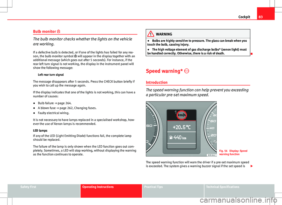
Fig. 56 Display: Speed
warning function
The speed warning function will warn the driver if a pre-set maximum speed
is exceeded. The system gives a warning buzzer signal if the set speed is
Safety FirstOperating InstructionsPractical TipsTechnical Specifications
Page 86 of 317
84Cockpit
exceeded by about 10 km/h. A warning symbol will also appear in the dis-
play ⇒ Fig. 56.
The speed warning function has two different warning speeds, which oper-
ate independently and serve slightly different purposes:
Speed limit warning 1
With speed limit warning 1, the maximum speed can be changed while driv-
ing. The speed limit that has been set remains stored until the ignition is
switched off, or until it is changed or cleared.
The warning symbol for speed limit warning 1 ⇒ Fig. 56 will appear in the
display if you exceed the pre-set speed. It goes out again if the speed is re-
duced below the set speed limit.
The symbol also goes out if the speed is increased to more than about
40 km/h above the set speed for at least 10 seconds. However, this does
not cancel the speed limit that was originally set.
Setting speed limit warning 1 ⇒ page 84.
Speed limit warning 2
With speed limit warning 2, the speed limit can only be changed or cleared
when the ignition is switched off. You are recommended to store this speed
limit warning if you always wish to be reminded of a particular speed limit.
This could be when driving in countries with general speed limits, or if a
particular speed should not be exceeded when winter tyres are fitted etc.
The speed limit warning symbol for speed warning 2 will appear in the
display if you exceed the pre-set speed. Unlike speed limit warning 1, the
warning symbol only goes out once the road speed has dropped below the
set value again.
Setting speed limit warning 2 ⇒ page 85.
Note
Please bear in mind that, even with the speed warning function, it is still im-
portant to keep an eye on the vehicle's speed with the speedometer and to
observe the legal speed limits.
Setting speed limit warning 1
Use the CHECK button to set speed limit warning 1.
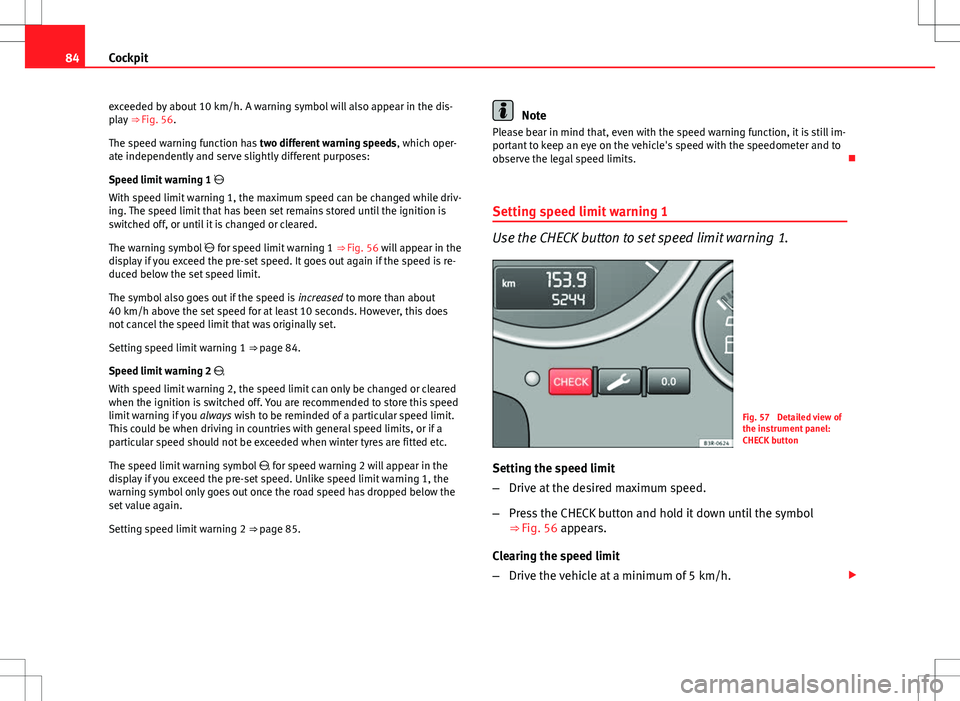
Fig. 57 Detailed view of
the instrument panel:
CHECK button
Setting the speed limit
– Drive at the desired maximum speed.
– Press the CHECK button and hold it down until the symbol
⇒ Fig. 56 appears.
Clearing the speed limit
– Drive the vehicle at a minimum of 5 km/h.
Page 87 of 317
85
Cockpit
– Press the CHECK button for at least two seconds.
The speed warning symbol lights up briefly in the display when the but-
ton is released to confirm that the selected speed has been stored. The
speed limit that has been selected remains stored until another speed is se-
lected with a brief push of the button, or until the memory is cleared with a
long push of the button.
Setting speed limit warning 2
Speed limit warning 2 is set using the switches on the wind-
screen wiper lever.
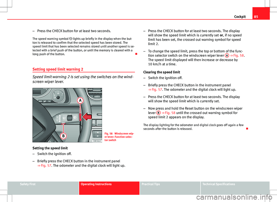
Fig. 58 Windscreen wip-
er lever: Function selec-
tor switch
Setting the speed limit
– Switch the ignition off.
– Briefly press the CHECK button in the instrument panel
⇒ Fig. 57. The odometer and the digital clock will light up. –
Press the CHECK button for at least two seconds. The display
will show the speed limit which is currently set or, if no speed
limit has been set, the crossed out warning symbol for speed
limit 2.
– To change the speed limit, press the top or bottom of the func-
tion selector switch on the windscreen wiper lever A
⇒ Fig. 58.
The speed limit displayed will then increase or decrease by
10 km/h at a time.
Clearing the speed limit
– Switch the ignition off.
– Briefly press the CHECK button in the instrument panel
⇒ Fig. 57. The odometer and the digital clock will light up.
– Press the CHECK button for at least two seconds. The display
will show the speed limit which is currently set.
– Now press and hold the Reset button on the windscreen wiper
lever B
⇒ Fig. 58 until the crossed out warning symbol for
speed limit 2 appears on the display.
The display lighting for the odometer and digital clock goes off again a few
seconds after the button is released.
Safety FirstOperating InstructionsPractical TipsTechnical Specifications
Page 88 of 317
86Cockpit
Onboard computer
Introduction
The onboard computer provides you with useful information
during a journey, including average and current fuel con-
sumption, average speed, distance to empty, driving time
and distance covered.
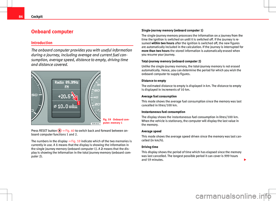
Fig. 59 Onboard com-
puter: memory 1
Press RESET button B
⇒ Fig. 60 to switch back and forward between on-
board computer functions 1 and 2.
The numbers in the display ⇒ Fig. 59 indicate which of the two memories is
currently in use. A 1 means that the display is showing the information in
the single journey memory (onboard computer 1). A 2 means that the dis-
play is showing the information in the total journey memory (onboard com-
puter 2). Single-journey memory (onboard computer 1)
The single-journey memory processes the information on a journey from the
time the ignition is switched on until it is switched off. If the journey is re-
sumed within two hours after the ignition is switched off, the new figures
are automatically included in the calculation. If the journey is interrupted for
more than two hours the stored information is automatically erased when
you resume your journey.
Total-journey memory (onboard computer 2)
Unlike the single-journey memory, the total-journey memory is not erased
automatically. Hence, you can determine the period for which you wish the
onboard computer to supply figures.
Distance to empty
The estimated distance to empty is displayed in km. The distance to empty
is displayed in increments of 10 km.
Average fuel consumption
This mode shows the average fuel consumption since the memory was last
cancelled in litres/100 km.
Instantaneous fuel consumption
The display shows the instantaneous fuel consumption in litres/100 km.
When the vehicle is stationary, the computer will display the last value in
the memory.
Average speed
This mode shows the average speed driven since the memory was last can-
celled (in km/h).
Driving time
This display shows the period of time which has elapsed since the memory
was last cancelled. The longest possible period it can cover is 999 hours
and 59 minutes.
Page 89 of 317
87
Cockpit
Driving time warning
After 2 hours of continuous driving, the display automatically switches over
to the driving time display of 2:00. At the same time the driving time display
starts flashing. This is to remind the driver to take a break.
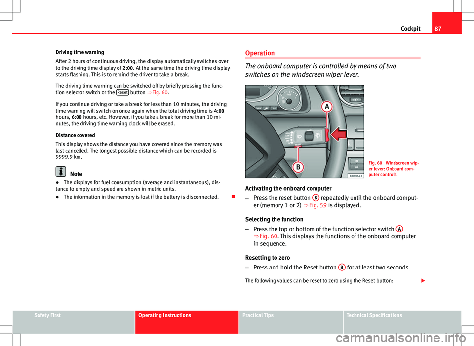
The driving time warning can be switched off by briefly pressing the func-
tion selector switch or the Reset
button ⇒ Fig. 60.
If you continue driving or take a break for less than 10 minutes, the driving
time warning will switch on once again when the total driving time is 4:00
hours, 6:00 hours, etc. However, if you take a break for more than 10 mi-
nutes, the driving time warning clock will be erased.
Distance covered
This display shows the distance you have covered since the memory was
last cancelled. The longest possible distance which can be recorded is
9999.9 km.
Note
● The displays for fuel consumption (average and instantaneous), dis-
tance to empty and speed are shown in metric units.
● The information in the memory is lost if the battery is disconnected. Operation
The onboard computer is controlled by means of two
switches on the windscreen wiper lever.
Fig. 60 Windscreen wip-
er lever: Onboard com-
puter controls
Activating the onboard computer
– Press the reset button B
repeatedly until the onboard comput-
er (memory 1 or 2) ⇒ Fig. 59 is displayed.
Selecting the function
– Press the top or bottom of the function selector switch A
⇒ Fig. 60. This displays the functions of the onboard computer
in sequence.
Resetting to zero
– Press and hold the Reset button B
for at least two seconds.
The following values can be reset to zero using the Reset button:
Safety FirstOperating InstructionsPractical TipsTechnical Specifications
Page 90 of 317
88Cockpit
● Journey duration
● Distance covered
● Average fuel consumption
● Average speed
The onboard computer can only be operated when the ignition is switched
on. When the ignition is switched on, the display shows the function that
was last selected.
As well as the figures from the onboard computer (1 or 2), the display can
also show information from the navigation system*. Press the Reset button B
briefly to switch back and forward between these displays.
Note
● If you keep the Reset button pressed for longer than two seconds, it will
reset the currently displayed figure to zero (for instance average fuel con-
sumption).
● Faults detected by the auto-check control will be displayed even if the
display is off.
● The information in the memory is lost if the battery is disconnected.
Page 91 of 317
89
Cockpit
Menu display
Introduction
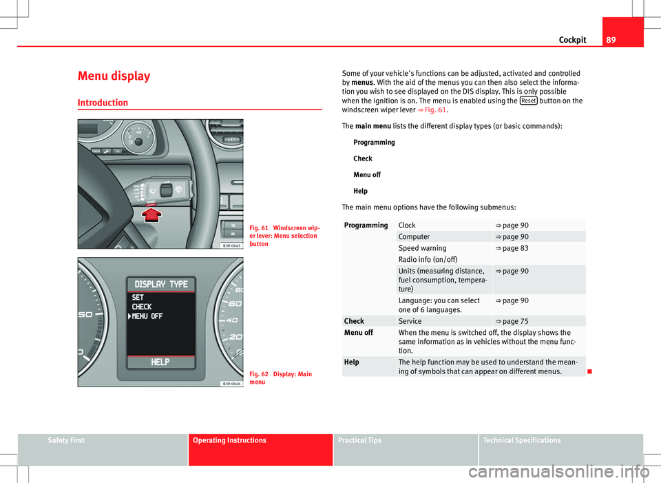
Fig. 61 Windscreen wip-
er lever: Menu selection
button
Fig. 62 Display: Main
menu Some of your vehicle's functions can be adjusted, activated and controlled
by
menus. With the aid of the menus you can then also select the informa-
tion you wish to see displayed on the DIS display. This is only possible
when the ignition is on. The menu is enabled using the Reset
button on the
windscreen wiper lever ⇒ Fig. 61.
The main menu lists the different display types (or basic commands):
Programming
Check
Menu off
Help
The main menu options have the following submenus:
ProgrammingClock⇒ page 90Computer⇒ page 90Speed warning⇒ page 83Radio info (on/off) Units (measuring distance,
fuel consumption, tempera-
ture)⇒ page 90
Language: you can select
one of 6 languages.⇒ page 90
CheckService⇒ page 75Menu offWhen the menu is switched off, the display shows the
same information as in vehicles without the menu func-
tion.
HelpThe help function may be used to understand the mean-
ing of symbols that can appear on different menus.
Safety FirstOperating InstructionsPractical TipsTechnical Specifications
Page 92 of 317
90Cockpit
Controlling the menu
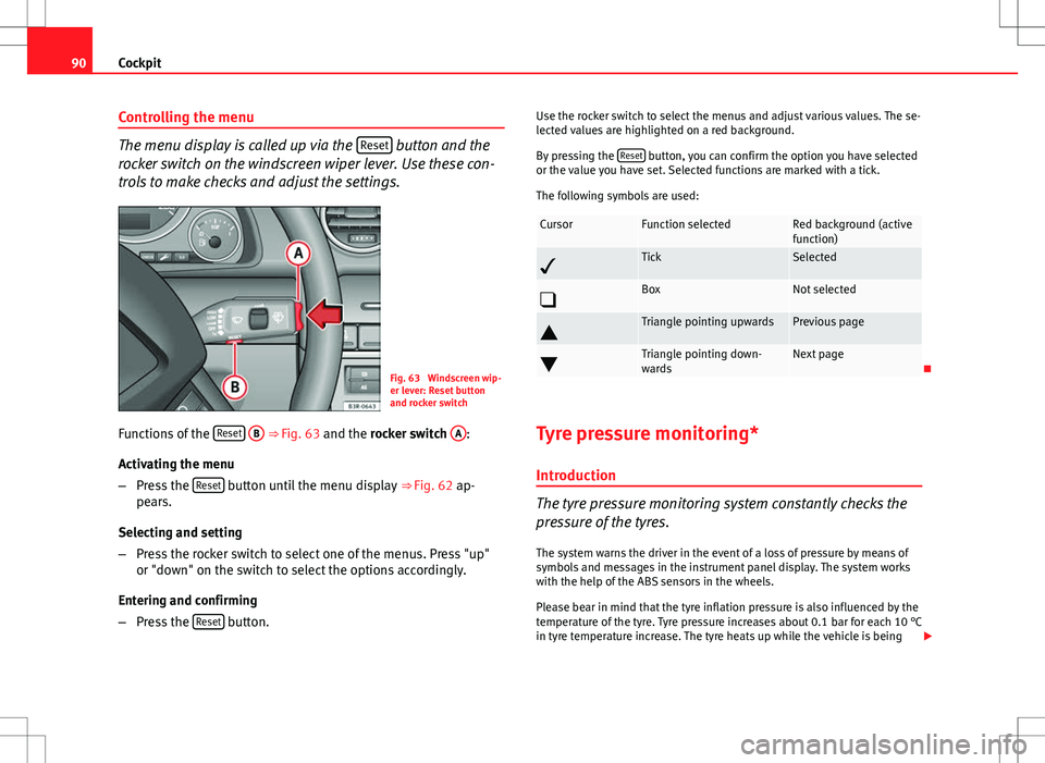
The menu display is called up via the Reset button and the
rocker switch on the windscreen wiper lever. Use these con-
trols to make checks and adjust the settings.
Fig. 63 Windscreen wip-
er lever: Reset button
and rocker switch
Functions of the Reset
B ⇒
Fig. 63 and the rocker switch A:
Activating the menu
– Press the Reset
button until the menu display
⇒ Fig. 62 ap-
pears.
Selecting and setting
– Press the rocker switch to select one of the menus. Press "up"
or "down" on the switch to select the options accordingly.
Entering and confirming
– Press the Reset
button. Use the rocker switch to select the menus and adjust various values. The se-
lected values are highlighted on a red background.
By pressing the
Reset
button, you can confirm the option you have selected
or the value you have set. Selected functions are marked with a tick.
The following symbols are used:
CursorFunction selectedRed background (active
function)
TickSelected
BoxNot selected
Triangle pointing upwardsPrevious page
Triangle pointing down-
wardsNext page
Tyre pressure monitoring* Introduction
The tyre pressure monitoring system constantly checks the
pressure of the tyres.
The system warns the driver in the event of a loss of pressure by means of
symbols and messages in the instrument panel display. The system works
with the help of the ABS sensors in the wheels.
Please bear in mind that the tyre inflation pressure is also influenced by the
temperature of the tyre. Tyre pressure increases about 0.1 bar for each 10 °C
in tyre temperature increase. The tyre heats up while the vehicle is being
Page 93 of 317
91
Cockpit
driven and the tyre pressure will rise accordingly. Therefore, you should only
adjust the tyre pressures when they are cold (i.e. approximately at ambient
temperature).
To ensure that the tyre pressure monitoring system works reliably, you
should check and, if necessary, adjust the tyre pressures at regular intervals
and store the correct pressures (reference values) in the system.
A tyre pressure information label is attached to the inside of the fuel tank
flap.
WARNING
● Never adjust tyre pressure when the tyres are hot. This may damage
or even burst the tyres. Risk of accident!
● An insufficiently inflated tyre flexes a lot more at high speeds and
causes significant heating of the tyre. Under these conditions, the tyre
bead may be released or the tyre may burst. Risk of accident!
For the sake of the environment
Under-inflated tyres lead to increased fuel consumption and tyre wear.
Note
● Responsibility for ensuring that the tyres are correctly inflated remains
with the driver; the system can only provide assistance.
● Pressure can only be adjusted when the tyres are at ambient tempera-
ture. Tyre pressure monitoring display
The tyre pressure should be corrected as soon as possible if
it is too low.
If the symbol appears, the tyre pressure on at least one of the
wheels is too low.
– Stop the vehicle.
– Check the tyre(s).
– Correct the tyre pressure ⇒ page 242.
For more detailed information on the tyre pressure monitoring system,
please refer to ⇒ page 241.
Safety FirstOperating InstructionsPractical TipsTechnical Specifications
Page 94 of 317
92Steering wheel controls
Steering wheel controls
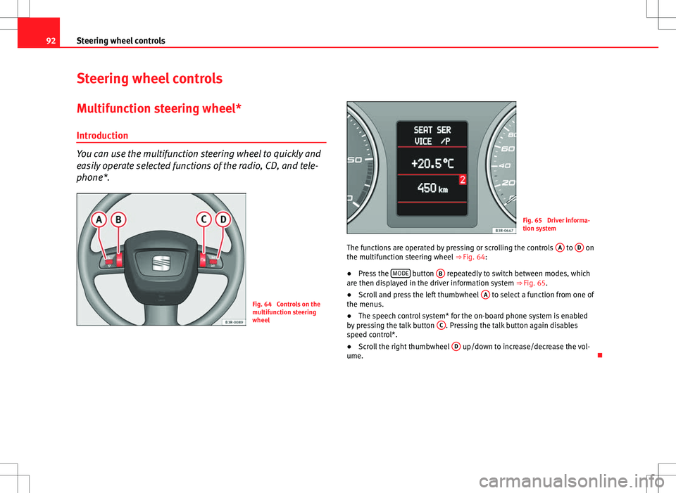
Multifunction steering wheel* Introduction
You can use the multifunction steering wheel to quickly and
easily operate selected functions of the radio, CD, and tele-
phone*.
Fig. 64 Controls on the
multifunction steering
wheel
Fig. 65 Driver informa-
tion system
The functions are operated by pressing or scrolling the controls A
to D on
the multifunction steering wheel ⇒ Fig. 64:
● Press the MODE
button
B repeatedly to switch between modes, which
are then displayed in the driver information system ⇒ Fig. 65.
● Scroll and press the left thumbwheel A
to select a function from one of
the menus.
● The speech control system* for the on-board phone system is enabled
by pressing the talk button C
. Pressing the talk button again disables
speed control*.
● Scroll the right thumbwheel D
up/down to increase/decrease the vol-
ume.