stop start Seat Exeo 2013 User Guide
[x] Cancel search | Manufacturer: SEAT, Model Year: 2013, Model line: Exeo, Model: Seat Exeo 2013Pages: 319, PDF Size: 4.81 MB
Page 82 of 319
80Cockpit
Engine oil level correct
If the symbol flashes and the engine oil level is correct, obtain profes-
sional assistance. Do not drive on! Do not continue to run the engine, even
at idle speed .
Note
The oil pressure warning lamp is not an indicator for the oil level. The oil
level should therefore be checked regularly, preferably every time you fill
the tank.
Yellow symbols
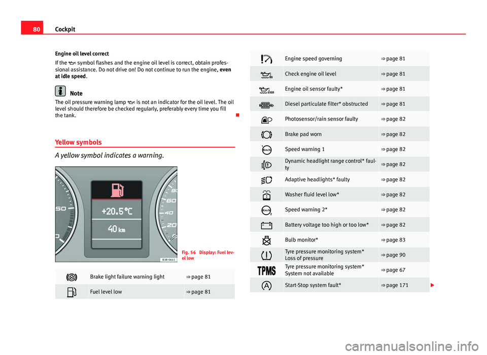
A yellow symbol indicates a warning.
Fig. 56 Display: Fuel lev-
el low
Brake light failure warning light⇒ page 81
Fuel level low⇒ page 81
Engine speed governing⇒ page 81
Check engine oil level⇒ page 81
Engine oil sensor faulty*⇒ page 81
Diesel particulate filter* obstructed⇒ page 81
Photosensor/rain sensor faulty⇒ page 82
Brake pad worn⇒ page 82
Speed warning 1⇒ page 82
Dynamic headlight range control* faul-
ty⇒ page 82
Adaptive headlights* faulty⇒ page 82
Washer fluid level low*⇒ page 82
Speed warning 2*⇒ page 82
Battery voltage too high or too low*⇒ page 82
Bulb monitor*⇒ page 83
Tyre pressure monitoring system*
Loss of pressure⇒ page 90
Tyre pressure monitoring system*
System not available⇒ page 67
Start-Stop system fault*⇒ page 171
Page 89 of 319
87
Cockpit
Driving time warning
After 2 hours of continuous driving, the display automatically switches over
to the driving time display of 2:00. At the same time the driving time display
starts flashing. This is to remind the driver to take a break.
The driving time warning can be switched off by briefly pressing the func-
tion selector switch or the Reset
button ⇒ Fig. 61.
If you continue driving or take a break for less than 10 minutes, the driving
time warning will switch on once again when the total driving time is 4:00
hours, 6:00 hours, etc. However, if you take a break for more than 10 mi-
nutes, the driving time warning clock will be erased.
Distance covered
This display shows the distance you have covered since the memory was
last cancelled. The longest possible distance which can be recorded is
9999.9 km.
Note
● The displays for fuel consumption (average and instantaneous), dis-
tance to empty and speed are shown in metric units.
● The information in the memory is lost if the battery is disconnected. Operation
The onboard computer is controlled by means of two
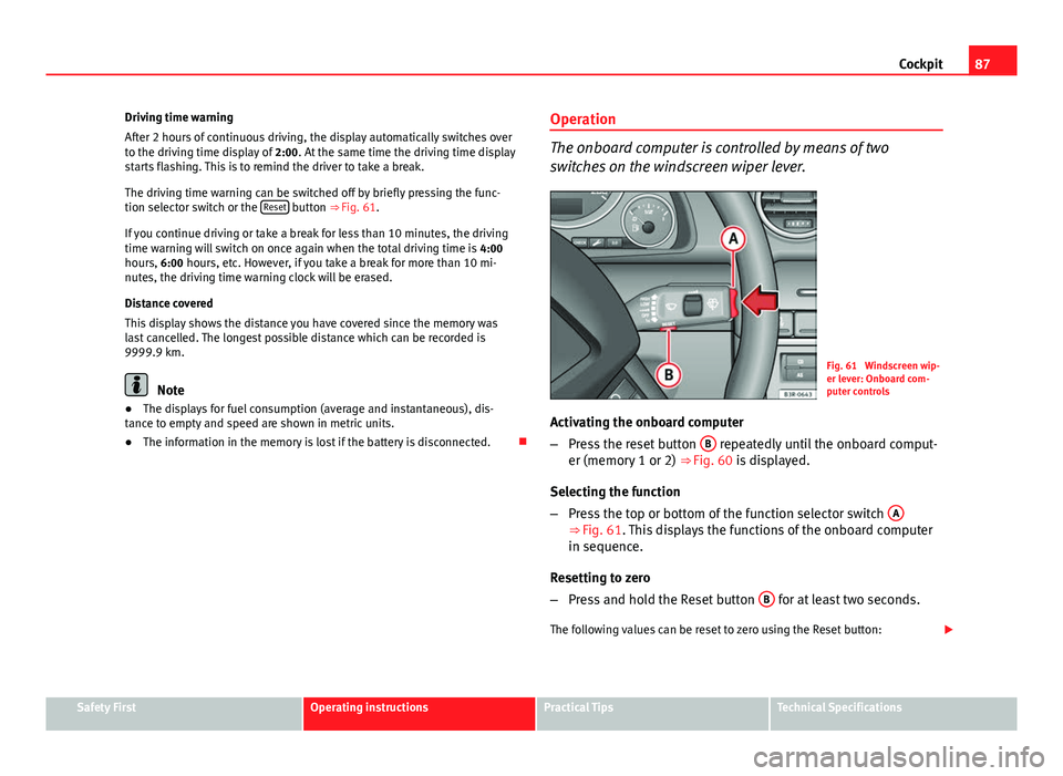
switches on the windscreen wiper lever.
Fig. 61 Windscreen wip-
er lever: Onboard com-
puter controls
Activating the onboard computer
– Press the reset button B
repeatedly until the onboard comput-
er (memory 1 or 2) ⇒ Fig. 60 is displayed.
Selecting the function
– Press the top or bottom of the function selector switch A
⇒ Fig. 61. This displays the functions of the onboard computer
in sequence.
Resetting to zero
– Press and hold the Reset button B
for at least two seconds.
The following values can be reset to zero using the Reset button:
Safety FirstOperating instructionsPractical TipsTechnical Specifications
Page 95 of 319
93
Steering wheel controls
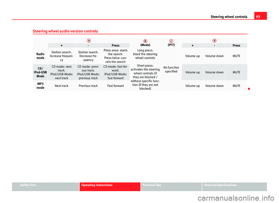
Steering wheel audio version controls
AB(Mode)C(PTT)D+-Press+-Press
Radio modeStation search.
Increase frequen- cyStation search.Decrease fre- quencyPress once: starts the search.
Press twice: can- cels the searchLong press:
block the steering wheel controls
Short press:
activates the steering wheel controls (if
they are blocked /
without specific func- tion (if they are not blocked)
No functionspecified
Volume upVolume downMUTE
CD/
iPod-USB ModeCD mode: next track.
iPod/USB Mode: next trackCD mode: previ-ous track.
iPod/USB Mode: previous trackCD mode: fast for- ward.
iPod/USB Mode: fast forward
Volume upVolume downMUTE
MP3
modeNext trackPrevious trackFast forwardVolume upVolume downMUTE
Safety FirstOperating instructionsPractical TipsTechnical Specifications
Page 97 of 319
95
Steering wheel controls
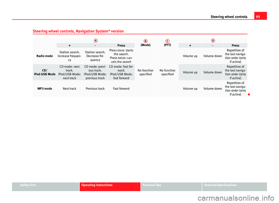
Steering wheel controls, Navigation System* version
AB(Mode)C(PTT)D+-Press+-Press
Radio modeStation search.
Increase frequen- cyStation search.Decrease fre- quencyPress once: starts the search.
Press twice: can- cels the search
No function specifiedNo function specified
Volume upVolume down
Repetition of
the last naviga- tion order (only if active)
CD/
iPod-USB ModeCD mode: next track.
iPod/USB Mode: next trackCD mode: previ-ous track.
iPod/USB Mode: previous trackCD mode: fast for- ward.
iPod/USB Mode: fast forward
Volume upVolume down
Repetition of
the last naviga- tion order (only if active)
MP3 modeNext trackPrevious trackFast forwardVolume upVolume down
Repetition of
the last naviga- tion order (only if active)
Safety FirstOperating instructionsPractical TipsTechnical Specifications
Page 99 of 319
97
Opening and closing
Opening and closing
Remote control keys
Set of keys
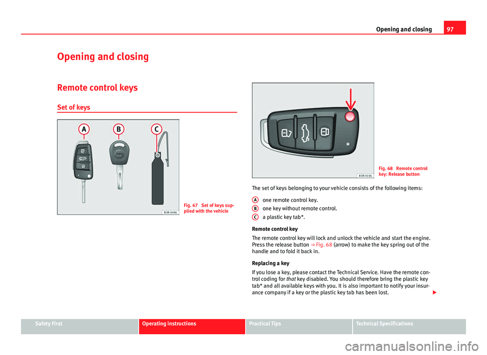
Fig. 67 Set of keys sup-
plied with the vehicle
Fig. 68 Remote control
key: Release button
The set of keys belonging to your vehicle consists of the following items: one remote control key.
one key without remote control.
a plastic key tab*.
Remote control key
The remote control key will lock and unlock the vehicle and start the engine.
Press the release button ⇒ Fig. 68 (arrow) to make the key spring out of the
handle and to fold it back in.
Replacing a key
If you lose a key, please contact the Technical Service. Have the remote con-
trol coding for that key disabled. You should therefore bring the plastic key
tab* and all available keys with you. It is also important to notify your insur-
ance company if a key or the plastic key tab has been lost.
A
BC
Safety FirstOperating instructionsPractical TipsTechnical Specifications
Page 101 of 319
99
Opening and closing
– Insert the new battery. Make sure that the “+” symbol on the
battery is facing downwards. The correct polarity is indicated on
the cover.
– After inserting the battery, align the cover and key and press
the two parts together.
For the sake of the environment
Used batteries must be disposed of at an appropriate waste facility or
through an authorised service, given that their components can affect the
environment.
Note
● The system must be re-synchronised after each battery replacement to
be able to lock and unlock the vehicle using the remote control
⇒ page 107.
● The new battery must be of the same type as the original.
Electronic immobiliser
The electronic immobiliser is designed to prevent unauthor-
ised persons from starting up the vehicle.
There is an electronic chip inside the key which automatically deactivates
the immobiliser when the key is inserted into the ignition lock. The electron-
ic immobiliser is enabled automatically when the ignition key is removed
from the ignition lock after coming to a stop.
If an uncoded key is used, the message SAFE* will appear in the trip record-
er display.
Note
● The engine can only be started using an original SEAT key with the cor-
rect code.
● It may not be possible to start the engine with the key if there is another
ignition key from a different make of vehicle on the same key tab.
Central locking system
Description
The central locking system enables you to lock and unlock
all the doors, the rear lid and the tank flap together. The central locking system on your vehicle locks and unlocks all the doors
and the tank flap simultaneously. The rear lid is unlocked when the vehicle
is opened. However, the handle must be used to open it. The vehicle can be
locked and unlocked using the remote control ⇒ page 105 or by turning the
key in the lock in the driver door.
The windows can also be centrally opened or closed using the central lock-
ing system ⇒ page 111. The sunroof* can be closed but not opened using
the central locking system.
The central locking system is combined with an anti-theft security system.
If the vehicle is locked with the key from the outside, the interior opening
levers stop working, which prevents unauthorised persons from entering
the vehicle.
Should the central locking system fail to work, you can activate all the locks
individually.
Safety FirstOperating instructionsPractical TipsTechnical Specifications
Page 107 of 319
105
Opening and closing
Childproof lock
Childproof locks on rear doors
The childproof lock prevents the rear doors from being
opened from the inside.
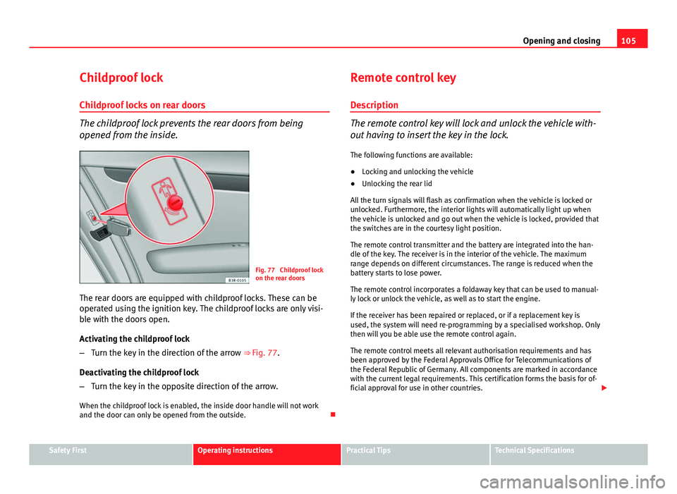
Fig. 77 Childproof lock
on the rear doors
The rear doors are equipped with childproof locks. These can be
operated using the ignition key. The childproof locks are only visi-
ble with the doors open.
Activating the childproof lock
– Turn the key in the direction of the arrow ⇒ Fig. 77.
Deactivating the childproof lock
– Turn the key in the opposite direction of the arrow.
When the childproof lock is enabled, the inside door handle will not work
and the door can only be opened from the outside. Remote control key
Description
The remote control key will lock and unlock the vehicle with-
out having to insert the key in the lock. The following functions are available:
● Locking and unlocking the vehicle
● Unlocking the rear lid
All the turn signals will flash as confirmation when the vehicle is locked or
unlocked. Furthermore, the interior lights will automatically light up when
the vehicle is unlocked and go out when the vehicle is locked, provided that
the switches are in the courtesy light position.
The remote control transmitter and the battery are integrated into the han-
dle of the key. The receiver is in the interior of the vehicle. The maximum
range depends on different circumstances. The range is reduced when the
battery starts to lose power.
The remote control incorporates a foldaway key that can be used to manual-
ly lock or unlock the vehicle, as well as to start the engine.
If the receiver has been repaired or replaced, or if a replacement key is
used, the system will need re-programming by a specialised workshop. Only
then will you be able use the remote control again.
The remote control meets all relevant authorisation requirements and has
been approved by the Federal Approvals Office for Telecommunications of
the Federal Republic of Germany. All components are marked in accordance
with the current legal requirements. This certification forms the basis for of-
ficial approval for use in other countries.
Safety FirstOperating instructionsPractical TipsTechnical Specifications
Page 111 of 319
109
Opening and closing
Deactivating the tow-away protection
– Open the door and pull out switch B
(with the symbol
) to
one side of the storage compartment, in the driver door
⇒ Fig. 79.
– Lock the vehicle.
The LED on switch
will light up when the
interior monitoring is disabled.
The LED on the top of the driver door trim will also light up for about 3 sec-
onds. When the vehicle is locked, the LED on the top of the driver door trim
will flash rapidly for about 3 seconds. About 30 seconds later it starts flash-
ing slowly. The interior monitoring is automatically enabled again the next
time the vehicle is locked.
The LED on switch
will light up when the
tow-away protection function is
disabled. The LED on the top of the driver door trim will also light up for
about 3 seconds. When the vehicle is locked, the LED on the top of the driv-
er door trim will flash rapidly for about 3 seconds. The tow-away protection
is automatically enabled again the next time the vehicle is locked.
WARNING
Do not leave anyone (especially children) in the vehicle if it is locked from
the outside and the anti-theft security system is enabled, as the doors
and windows cannot then be opened from the inside. Locked doors could
delay assistance in an emergency, potentially putting lives at risk.
Electric windows
Controls
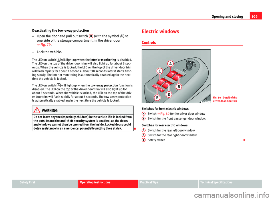
Fig. 80 Detail of the
driver door: Controls
Switches for front electric windows Switch ⇒ Fig. 80 for the driver door window
Switch for the front passenger door window.
Switches for rear electric windows Switch for the rear left door window
Switch for the rear right door window
Safety switch
A
B
CDE
Safety FirstOperating instructionsPractical TipsTechnical Specifications
Page 112 of 319
110Opening and closing
WARNING
● Always take the key with you when leaving the vehicle, even if you
only intend to be gone for a short time. This is particularly important if
there are children in the vehicle, as they might otherwise be able to start
the engine or use power-operated equipment (e.g. the electric windows),
which could cause injuries. The electric window switches are only disa-
bled when the driver door or the front passenger door is opened.
● Never close the windows in a careless or uncontrolled manner, as
there is a risk of causing injuries.
● When locking the vehicle from the outside, make sure that nobody is
inside the vehicle, as the windows cannot be opened from the inside in
an emergency.
Switches on the driver door
The driver can operate all the electric windows in the vehi-
cle. The electric windows are controlled by two-stage switches:
Opening the windows
– Press the switch as far as the first stop and hold it until the win-
dow has moved to the desired position.
– Press the switch briefly to the second stop and the window will
automatically open all the way.
Closing the windows
– Pull the switch as far as the first stop and hold it until the win-
dow has moved to the desired position. –
Pull the switch briefly to the second stop and the window will
automatically close all the way.
Safety switch
The safety switch ⇒ Fig. 80 E
can deactivate the rear door switches. The
windows can only be operated from the rear when the safety switch is press-
ed in.
The symbol lights up on the safety switch when the electric windows in
the rear doors are disabled (switch not pressed in).
Note
The windows will work for about ten minutes after the ignition has been
switched off. The electric window switches are only disabled when the driver
door or the front passenger door is opened.
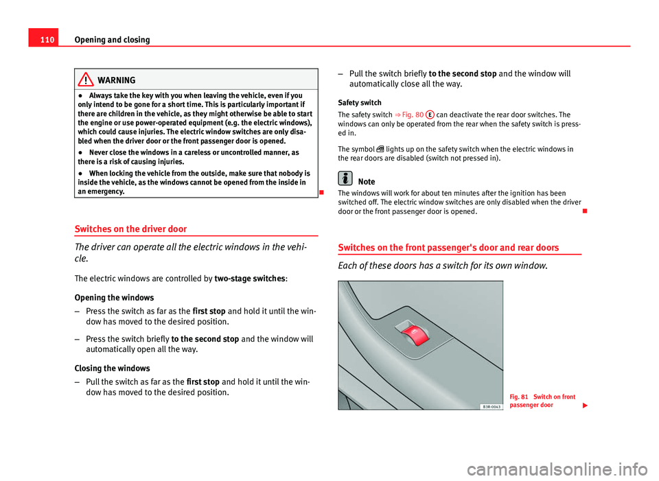
Switches on the front passenger's door and rear doors
Each of these doors has a switch for its own window.
Fig. 81 Switch on front
passenger door
Page 115 of 319
113
Opening and closing
– With the control in position 0, press the control briefly to make
the roof tilt open all the way.
– To open the roof as far as an intermediate setting, press and
hold the control until the roof has moved to the desired posi-
tion.
When you release the switch it will automatically spring back from position 2
to position 1.
The sliding sun blind in the headliner automatically opens when the sunroof
is slid open. If required, it can be closed by hand when the sunroof is
closed.
It is advisable to close the sun blind when the vehicle is left standing in the
sun. It is important to remember to close the sunroof when parking the vehi-
cle or if it suddenly starts raining, especially when the sun blind is closed.
For further information on the automatic close function, see ⇒ page 113.
Closing
Closing
– Turn the control to position 0
⇒ Fig. 82 to close the sunroof
⇒ .
Closing the sunroof from the tilt position
– Pull the specially formed rear end of the control and hold it until
the sunroof has moved down to the desired position.
– Pull the switch briefly to lower the sunroof automatically to the
fully closed position. If required, the sunroof can be stopped in
any position by briefly pulling the control again ⇒
.
WARNING
Take care when closing the sunroof. There is a risk of suffering injury. For
this reason, always take out the ignition key when leaving the vehicle.
Automatic close function
The sunroof can also be closed from outside the vehicle.
– Turn the key in the lock on the driver door and hold it in the lock
position or press the lock button on the remote control until the
sunroof has closed all the way ⇒
.
WARNING
Take care when closing the sunroof. There is a risk of suffering injury.
Solar sunroof*
The solar cells in the sunroof power the air conditioner fan.
The solar sunroof is operated in the same way as the normal sliding/tilting
sunroof.
The interior trim is fixed to the solar sunroof and cannot be opened and
closed separately.
Safety FirstOperating instructionsPractical TipsTechnical Specifications