tyre pressure Seat Exeo ST 2010 Owner's Guide
[x] Cancel search | Manufacturer: SEAT, Model Year: 2010, Model line: Exeo ST, Model: Seat Exeo ST 2010Pages: 325, PDF Size: 9.34 MB
Page 254 of 325

Wheels and tyres
252
For the sake of the environmentOld tyres must be disposed of according to the laws in the country concerned.
Note
•For technical reasons, it is not generally possible to use the wheels from
other vehicles. This can also apply to wheels of the same model. The use of
wheels or tyres which have not been approved by SEAT for use with your
model may invalidate the vehicle's type approval for use on public roads.•If the spare tyre is not the same as the tyres that are mounted on the
vehicle - for example with winter tyres - you should only use the spare tyre for
a short period of time and drive with extra care. Refit the normal road wheel
as soon as possible.Wheel bolts
Wheel bolts must be tightened to the correct torque.The design of wheel bolts is matched to the rims. If different wheel rims are
fitted, the correct wheel bolts with the right length and correctly shaped bolt
heads must be used. This ensures that wheels are fitted securely and that the
brake system functions correctly.
In certain circumstances, you should not use wheel bolts from a different
vehicle, even if it is the same model ⇒page 223.
After the wheels have been changed, the tightening torque of the wheel bolts
s ho uld b e che cke d as s o on as p ossible wit h a to rqu e w re nch. ⇒ The tight-
ening torque for steel and alloy wheels is 120 Nm.
WARNING
If the wheel bolts are not tightened correctly, the wheel could become
loose while driving. Risk of accident.•The wheel bolts must be clean and turn easily. Never apply grease or oil
to them.•Use only wheel bolts which belong to the wheel.•If the torque of the wheel bolts is too low, they could loosen whilst the
vehicle is in motion. Risk of accident! If the tightening torque is too high,
the wheel bolts and threads can be damaged.Caution
The prescribed tightening torque for wheel bolts for steel and alloy wheels is
120 Nm.Winter tyres
Winter tyres will improve the vehicles handling on snow and
ice.In winter conditions winter tyres will considerably improve the vehicle's
handling. The design of summer tyres (width, rubber compound, tread
pattern) gives less grip on ice and snow.
Winter tyres must be inflated to a pressure 0.2 bar higher than the pressures
specified for summer tyres (see sticker on tank flap).
Winter tyres must be fitted on all four wheels.
Information on permitted winter tyre sizes can be found in the vehicle's regis-
tration documents. Use only radial winter tyres. All tyre sizes listed in the
vehicle documentation also apply to winter tyres.
ExeoST_EN.book Seite 252 Freitag, 3. September 2010 11:41 11
Page 257 of 325

If and when255
Safety First
Operating Instructions
Practical Tips
Technical Specifications
•A hook for removing wheel covers* or hub caps•Box spanner for wheel bolts•A screwdriver with reversible blade•Towing eye•An adapter for the anti-theft wheel bolts*
Before replacing the jack in the storage bin, wind down the arm of the jack as
far as it will go.
Some of the tools listed are only provided in certain models or are optional
extras.WARNING
•Do not use the hexagonal socket in the screwdriver handle to tighten
the wheel bolts, as with this it is not possible to tighten the bolts to the
required torque. Risk of accident.•The factory-supplied jack is only designed for changing wheels on this
model. On no account attempt to use it for lifting heavier vehicles or other
loads. Risk of injury.•Never start the engine when the vehicl e is raised. Failure to do so could
result in an accident.•I f w o r k is t o b e ca r r ie d o u t un d e r n ea t h t h e v e h ic l e , t h is m u s t be s e cu re d
by suitable stands. Otherwise, there is a risk of injury.
Tyre mobility system
The tyre mobility system is stored under the floor panel in the
luggage compartment.– Take hold of the handle and fold back the floor panel in the luggage compartment.
– Take out the tyre mobility system.Your vehicle is equipped with a Tyre Mobility System in case of a puncture.
The tyre mobility system consists of a container with sealing compound and
a compressor to generate the required tyre pressure.
Instructions for using the sealant compound and the compressor are
included with the sealant can.
Fig. 191 Tyre Mobility
System under floor panel
in luggage compartment
ExeoST_EN.book Seite 255 Freitag, 3. September 2010 11:41 11
Page 258 of 325

If and when
256Spare steel rim wheel
The spare steel rim wheel is carried in the wheel well under
the floor panel in the luggage compartment. It is only
intended for temporary use over short distances.Taking out the spare wheel
–Turn the plastic knob ⇒fig. 192 anti-clockwise.
– Take out the spare wheel.
Securing the defective wheel in the spare wheel well
– Place wheel in spare wheel well in the luggage compartment.
– Secure the wheel by turning plastic knob clockwise.
– Replace the floor panel before closing the tailgate.
Your vehicle can be factory-equipped with a spare steel wheel. The spare
wheel does not usually meet the same performance standards as the wheels
fitted on the vehicle because of the wheel/tyre dimensions, rubber composi-
tion, tread pattern, etc. Therefore, note the following restrictions:•The spare steel wheel is designed only for your vehicle model. Do not
attempt to mount the wheel on any vehicle but your own.•Your vehicle will have different driving characteristics when the spare
steel rim wheel is mounted ⇒ .•The spare wheel is only intended for temporary use after having a flat tyre.
Replace the spare wheel with a normal wheel that has the proper tyre dimen-
sions as soon as possible.•If the size of the spare steel rim wheel is different to that of the other
wheels, it is unlikely that snow chains suitable for the other wheels will fit it.WARNING
•After mounting the spare steel rim wheel, the tyre pressure must be
checked and corrected as soon as possible. The tyre pressure must corre-
spond to the vehicle load (consult the table containing the inflation pres-
sures). Otherwise there is danger of causing an accident. Use the highest
tyre pressure as indicated in the table.•Do not drive faster than 80 km/h, as higher speeds can cause an acci-
dent.•Avoid heavy acceleration, hard braking and fast cornering, as this could
cause an accident.
Fig. 192 Spare steel rim
wheel
ExeoST_EN.book Seite 256 Freitag, 3. September 2010 11:41 11
Page 260 of 325
If and when
258
–The inflation pressure of the newly fitted spare tyre must be
checked as soon as possible.
–Have the tightening torque of the wheel bolts checked as soon
as possible with a torque wrench. It must be 120 Nm (always
when cold)
–Have the flat tyre replaced as quickly as possible.
Note•If you notice that the wheel bolts are rusty and difficult to turn when
changing a wheel, they must be replaced before having the tightening torque
checked.•For your safety, drive at moderate speeds until the wheel bolt tightening
torque has been checked.
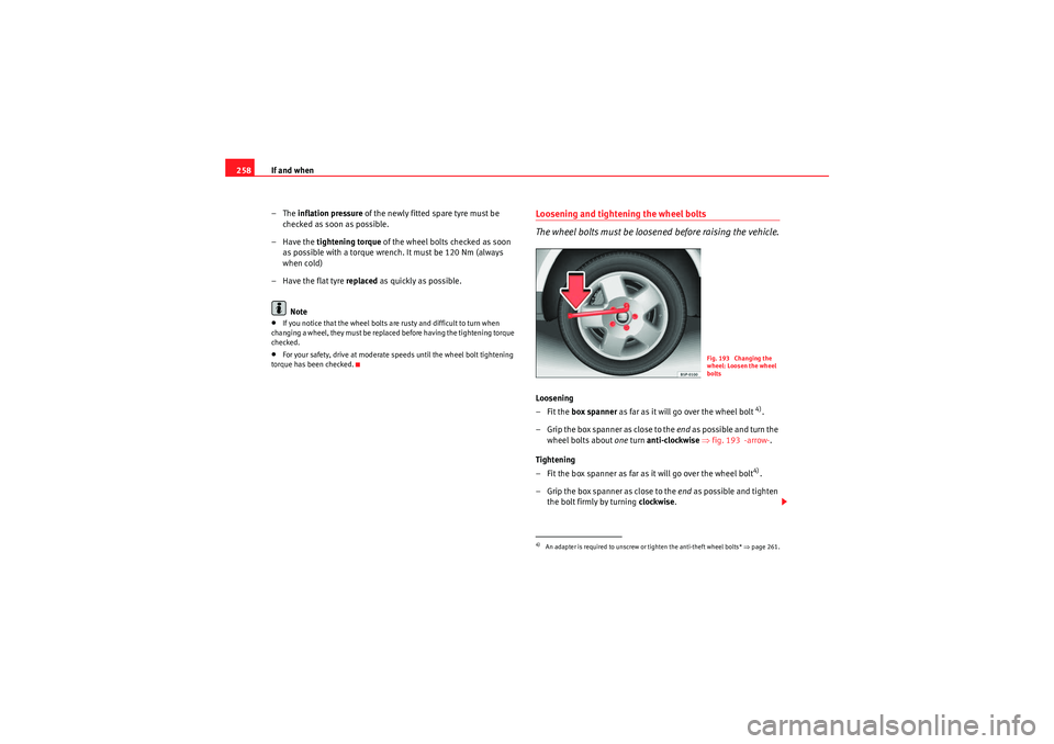
Loosening and tightening the wheel bolts
The wheel bolts must be loosened before raising the vehicle.Loosening
–Fit the box spanner as far as it will go over the wheel bolt
4).
– Grip the box spanner as close to the end as po ssible an d turn t he
wheel bolts about one turn anti-clockwise ⇒ fig. 193 -arrow- .
Tightening
– Fit the box spanner as far as it will go over the wheel bolt4).
– Grip the box spanner as close to the end as possible and tighten
the bolt firmly by turning clockwise.
4)An adapter is required to unscrew or tighten the anti-theft wheel bolts* ⇒page 261.
Fig. 193 Changing the
wheel: Loosen the wheel
bolts
ExeoST_EN.book Seite 258 Freitag, 3. September 2010 11:41 11
Page 264 of 325
If and when
262Tyre repairs* (Tyre Mobility System)General information and safety notes
Repaired tyres are only suitable for temporary use over a
short period.Your vehicle is equipped with a tyre repair kit: the Tyre Mobilit y System .
In the event of a puncture you will find the TMS, which consists of a sealing
compound and a compressor, located under the floor panel in the luggage
compartment.
The Tyre Mobil it y Syste m will reliably seal tyres damaged by foreign bodies,
provided that the cuts or punctures are no larger than approx. 4 mm in diam-
eter.
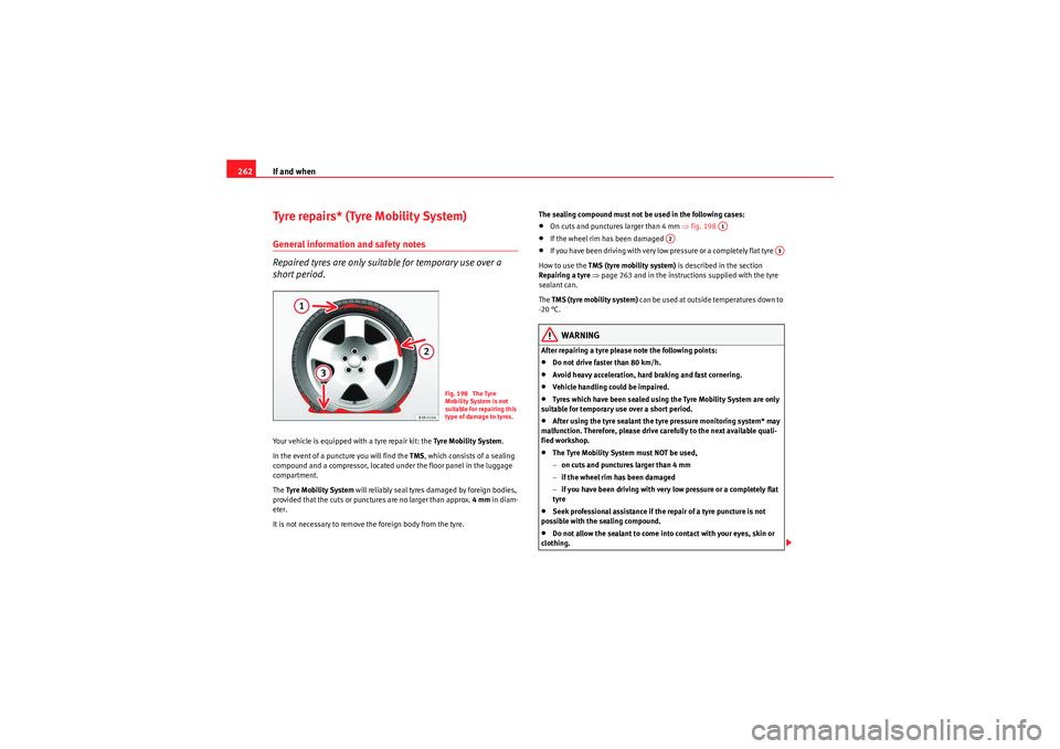
It is not necessary to remove the foreign body from the tyre. The sealing compound must not be used in the following cases:
•On cuts and punctures larger than 4 mm
⇒fig. 198 •If the wheel rim has been damaged •If you have been driving with ver y low pressure or a completely flat tyre
How to use the TMS (tyre mobility system) is described in the section
Repairing a tyre ⇒ page 263 and in the instructions supplied with the tyre
sealant can.
The TMS (tyre mobility system) can be used at outside temperatures down to
-20 °C.WARNING
After repairing a tyre please note the following points:•Do not drive faster than 80 km/h.•Avoid heavy acceleration, hard braking and fast cornering.•Vehicle handling could be impaired.•Tyres which have been sealed using the Tyre Mobility System are only
suitable for temporary use over a short period.•After using the tyre sealant the tyre pressure monitoring system* may
malfunction. Therefore, please drive carefully to the next available quali-
fied workshop.•The Tyre Mobility System must NOT be used,
− on cuts and punctures larger than 4 mm
− if the wheel rim has been damaged
− if you have been driving with very low pressure or a completely flat
tyre•Seek professional assistance if the repair of a tyre puncture is not
possible with the sealing compound.•Do not allow the sealant to come into contact with your eyes, skin or
clothing.
Fig. 198 The Tyre
Mobility System is not
suitable for repairing this
type of damage to tyres.
A1
A2
A3
ExeoST_EN.book Seite 262 Freitag, 3. September 2010 11:41 11
Page 266 of 325
If and when
264
– Stick the “max. 80 km/h” adhesive, which is included with the tyre sealant can, onto the instrument panel where the driver will
see it.
Filling the tyre
– Shake the tyre sealant can well.
– Screw the enclosed filling hose onto the sealant can as far as it will go. This will automatically pierce the foil sealing the can.
– Take the valve cap off the tyre valve and use the enclosed valve insert tool to unscrew the valve insert ⇒page 263, fig. 199 .
– Place the valve insert onto a clean surface.
– Remove the sealing plug from the filling hose and insert the hose into the tyre valve.
– Hold the tyre sealant can upside down and fill the complete contents of the can into the tyre.
– Then disconnect the hose and screw the valve insert firmly back into the tyre valve.
Inflating the tyre
– Screw the compressor filling hose onto the tyre valve and plug the connector into the cigarette lighter.
– Pump the tyre up to 2.0 to 2.5 bar and monitor the pressure shown on the pressure gauge. – If the tyre pressure remains lowe
r than the value specified above
drive the vehicle approx. 10 metres forwards or backwards, so
that the sealant can spread evenly in the tyre. If the pressure is
still lower than the specification the tyre is too badly damaged
and cannot be repaired using the tyre sealant.
Final check
– After about 10 minutes, stop to check the tyre pressure.
– If tyre pressure is less than 1.3 bar, the tyre is too badly damaged. Do not drive on! You should obtain professional
assistance.
WARNING
•If you have a puncture in heavy traffic, switch on the hazard warning
lights and place the warning triangle in a visible location. This is for your
own safety and also warns other road users.•Make su re your pass engers wait in a safe place ( for instance beh ind the
roadside crash barrier).•Please observe the manufacturer's safety notes on the compressor and
the instructions supplied with the tyre sealant can.•If it is not possible to build up a tyre pressure of 2.0 bar within 6
minutes this means that the tyre is too badly damaged. Do not drive on!•Seek professional assistance if the repair of a tyre puncture is not
possible with the sealing compound.•If tyre pressure is less than 1.3 bar after driving about 10 minutes, the
tyre is too badly damaged. Do not drive on! Obtain technical assistance.Caution
Take special care if you have to repair a tyre on a slope.
ExeoST_EN.book Seite 264 Freitag, 3. September 2010 11:41 11
Page 268 of 325

If and when
266
CautionNever “repair” damaged fuses and never replace them with fuses with a
higher rating. Failure to comply could result in fire. It could also cause
damage to other parts of the electrical system.
Note
If a newly replaced fuse blows again after a short time, the electrical system
must be checked by a qualified workshop as soon as possible.Fuse assignment
This list shows the fuses which can be replaced relatively
easily by the owner.No.
Consumer
Amps
1
Air conditioner
10
2
Footwell lamps
5
3
Heated washer jets
5
4
Radiator fan
5
5
Parking aid, automatic gearbox
10
6
Air conditioner (air purity sensor), pressure sensor
5
7
Electronic Stability Programme (ESP), brake light
switch, clutch pedal switch, steering angle sensor
10
8
Tele ph one
5
9
Va can t
10
Adaptive headlights right
5
11
Airbag and disconnection of the front passenger air-
bag
5
12
Diagnostic socket
10
13
Steering column unit
10
14
Brake lights
10
15
Instrument panel
10
16
Va can t
17
Tyre pressure control, rain/light sensor
10
18
Adaptive headlights left
5
19
Va can t
20
Va can t
21
Va can t
22
Driver door / front passenger door
15
23
Rear doors
15
24
Central electrics unit for convenience equipment
20
25
Heater blower
30
26
Rear window heater
30
27
Power socket for trailer (control unit)
30
28
Fuel pump, auxiliary pump for diesel
20
29
Va can t
30
Sliding/tilting sunroof
20
31
Diagnosis connection, automatic anti-dazzle interior
mirror, reverse light, automatic gearbox
15
32
Towing socket
15
No.
Consumer
Amps
ExeoST_EN.book Seite 266 Freitag, 3. September 2010 11:41 11
Page 302 of 325
Description of specifications
300If the maximum permissible drawbar load cannot be met (e.g. with small,
empty and light-weight single axle trailers or tandem axle trailers with a
wheelbase of less than 1 metre), at least 4% of the actual trailer weight is a
legal stipulation for a drawbar load.
WARNING
•For safet y reas ons , d o not excee d the 8 0 k m/h limit . Th is is als o valid in
countries where higher speeds are permitted.•Never exceed the maximum trailer weights or the drawbar load. If the
permissible axle load or the permissible total weight is exceeded, the
driving characteristics of the vehicle may change, leading to accidents,
injuries and damage to the vehicle.
WheelsTyre pressure, snow chains, wheel boltsTyre pressures
The sticker with the tyre pressure values can be found on the inside of the
tank flap. The tyre pressure values given there are for cold tyres. The slightly
raised pressures of warm tyres must not be reduced. ⇒
Snow chains
Snow chains may be fitted only to the front wheels.
Consult the chapter “wheels” of this manual.
Wheel bolts
After the wheels have been changed, the tightening torque of the wheel bolts
s ho uld b e che cke d as s o on as p ossible wit h a to rqu e w re nch ⇒. The tight-
ening torque for steel and alloy wheels is 120 Nm.
WARNING
•Check the tyre pressure at least once per month. Checking the tyre
pressure is very important. If the tyre pressure is too high or too low, there
is an increased danger of accidents, particularly at high speeds.•If the torque of the wheel bolts is too low, they could loosen while the
vehicle is in motion. Risk of accident! If the tightening torque is too high,
the wheel bolts and threads can be damaged.Note
We recommend that you ask your Authorised Service Centre for information
about appropriate wheel, tyre and snow chain size.
ExeoST_EN.book Seite 300 Freitag, 3. September 2010 11:41 11
Page 313 of 325

Technical Specifications311
Safety First
Operating Instructions
Practical Tips
Technical Specifications
Dimensions and capacities
Dimensions
Length, width 4661-4741
a) mm/ 1772 mm
a)With towing eye.Height at kerb weight 1454 mm with roof bars
Front and rear projection 976 mm/ 1048-1123
a) mm
Wheelbase 2642 mm
Turning circle 11.2 m
Track width
b)
b)This data will change depending on the type of wheel rim.
Front Rear
1522 mm 1523 mm
Capacities
Fuel tank 70 l. Reserve 10 l.
Windscreen washer fluid container with headlight washer 4.8 l.
Tyre pressure
Summer-grade tyres:
The correct tyre pressure can be seen on the sticker on the inside of the tank flap.
Winter tyres:
The pressure of these tyres is the same as the summer tyre pressure plus 0.2 bar.
ExeoST_EN.book Seite 311 Freitag, 3. September 2010 11:41 11
Page 318 of 325

Index
316Electronic Stability Programme
Description . . . . . . . . . . . . . . . . . . . . . . . . . 172
How the system works . . . . . . . . . . . . . . . . 191
Warning lamp . . . . . . . . . . . . . . . . . . . . . . . 173
Emergencies Changing a wheel . . . . . . . . . . . . . . . . . . . . 257
Disconnecting the battery . . . . . . . . . . . . . 241
Jack . . . . . . . . . . . . . . . . . . . . . . . . . . . . 254, 259
Sunroof emergency activation . . . . . . . . . . 114
Tools . . . . . . . . . . . . . . . . . . . . . . . . . . . . . . . 254
Tyre mobility system . . . . . . . . . . . . . . . . . . 255
Engine Running in . . . . . . . . . . . . . . . . . . . . . . . . . . 197
Starting . . . . . . . . . . . . . . . . . . . . . . . . . . . . 174
Stop . . . . . . . . . . . . . . . . . . . . . . . . . . . . . . . 175
Engine compartment Safety instructions . . . . . . . . . . . . . . . . . . . 229
Engine oil . . . . . . . . . . . . . . . . . . . . . . . . . . . . . . 230 Checking oil level . . . . . . . . . . . . . . . . . . . . 232
Consumption . . . . . . . . . . . . . . . . . . . . . . . . 232
Oil pressure too low . . . . . . . . . . . . . . . . . . . 78
Oil properties . . . . . . . . . . . . . . . . . . . . . . . . 231
Oil sensor defective . . . . . . . . . . . . . . . . . . . 80
Topping up . . . . . . . . . . . . . . . . . . . . . . . . . . 233
Engine speed governing . . . . . . . . . . . . . . . . . . . 80
Environment . . . . . . . . . . . . . . . . . . . . . . . . . . . 199 Environmental friendliness . . . . . . . . . . . . 201
Roof racks . . . . . . . . . . . . . . . . . . . . . . . . . . 152
Environmental tip Avoiding pollution . . . . . . . . . . . . . . . . . . . . 226
Environmentally friendly driving . . . . . . . . . . . 199 ESP
See Electronic Stability Programme . . . . . . 172
Exhaust gas purification system . . . . . . . . . . . 198
Exterior mirrors . . . . . . . . . . . . . . . . . . . . . . . . . 217
FFabric trim cleaning . . . . . . . . . . . . . . . . . . . . . 221
Fastening rings . . . . . . . . . . . . . . . . . . . . . . . . . . 17
Floor mats . . . . . . . . . . . . . . . . . . . . . . . . . . . . . . 16
Fog lights . . . . . . . . . . . . . . . . . . . . . . . . . . . . . . 118
Front airbags . . . . . . . . . . . . . . . . . . . . . . . . . . . . 32 Description . . . . . . . . . . . . . . . . . . . . . . . . . . 32
Operation . . . . . . . . . . . . . . . . . . . . . . . . . . . . 33
Safety notes . . . . . . . . . . . . . . . . . . . . . . . . . . 35
Front drink holder . . . . . . . . . . . . . . . . . . . . . . . 153
Front passenger airbag deactivation . . . . . . . . . 44
Fuel Diesel . . . . . . . . . . . . . . . . . . . . . . . . . . . . . . 227
Fuel gauge . . . . . . . . . . . . . . . . . . . . . . . . . . . 63
Fuel level low . . . . . . . . . . . . . . . . . . . . . . . . . 80
Instantaneous fuel consumption . . . . . . . . . 85
Petrol . . . . . . . . . . . . . . . . . . . . . . . . . . . . . . 226
Fuel tank opening the fuel tank flap . . . . . . . . . . . . . 225
Fuel: save . . . . . . . . . . . . . . . . . . . . . . . . . . . . . . 199
Fuse Assignment . . . . . . . . . . . . . . . . . . . . . . . . . 266
Changing . . . . . . . . . . . . . . . . . . . . . . . . . . . 265
GGear display . . . . . . . . . . . . . . . . . . . . . . . . . . . . 73
Gear shift pattern . . . . . . . . . . . . . . . . . . . . . . . 183
General overview of the engine compartment 301
Glove compartment . . . . . . . . . . . . . . . . . . . . . 159Light . . . . . . . . . . . . . . . . . . . . . . . . . . . . . . . 124
GRA . . . . . . . . . . . . . . . . . . . . . . . . . . . . . . . . . . 180HHandbrake . . . . . . . . . . . . . . . . . . . . . . . . . . . . . 176
Hazard warning lights . . . . . . . . . . . . . . . . . . . . 122
Head restraint Rear seat . . . . . . . . . . . . . . . . . . . . . . . . . . . 142
Head restraints Front seats . . . . . . . . . . . . . . . . . . . . . . . . . . 140
Rear seats . . . . . . . . . . . . . . . . . . . . . . . . . . 141
Removing and fitting . . . . . . . . . . . . . . . . . 141
Headlight range control . . . . . . . . . . . . . . . . . . 120 Dynamic . . . . . . . . . . . . . . . . . . . . . . . . . . . . 121
Faulty . . . . . . . . . . . . . . . . . . . . . . . . . . . . . . . 81
Headlights Adaptive headlights . . . . . . . . . . . . . . . . . . 122
Automatic headlight control . . . . . . . . . . . 117
Automatic headlight control photosensors 117
Coming home function . . . . . . . . . . . . . . . . 119
Driving abroad . . . . . . . . . . . . . . . . . . . . . . . 202
Front fog lights . . . . . . . . . . . . . . . . . . . . . . 118
Headlight range control . . . . . . . . . . . . . . . 120
ExeoST_EN.book Seite 316 Freitag, 3. September 2010 11:41 11