stop start Seat Exeo ST 2011 User Guide
[x] Cancel search | Manufacturer: SEAT, Model Year: 2011, Model line: Exeo ST, Model: Seat Exeo ST 2011Pages: 319, PDF Size: 5.12 MB
Page 99 of 319
97
Unlocking and locking
2 remote control keys
In certain European markets, vehicles with alarm are equipped with 2 re-
mote control keys.
WARNING
● Always take the key with you when leaving the vehicle, even if you
only intend to be gone for a short time. This is particularly important if
there are children in the vehicle, as they might otherwise be able to start
the engine or use power-operated equipment (e.g. the electric windows),
which could cause injuries.
● Wait for the vehicle to come to a standstill before removing the igni-
tion key from the lock! Otherwise, the steering lock could engage sud-
denly, causing an accident.
Indicator light on the remote control key
The condition of the battery in the remote control key is
monitored by the indicator light.
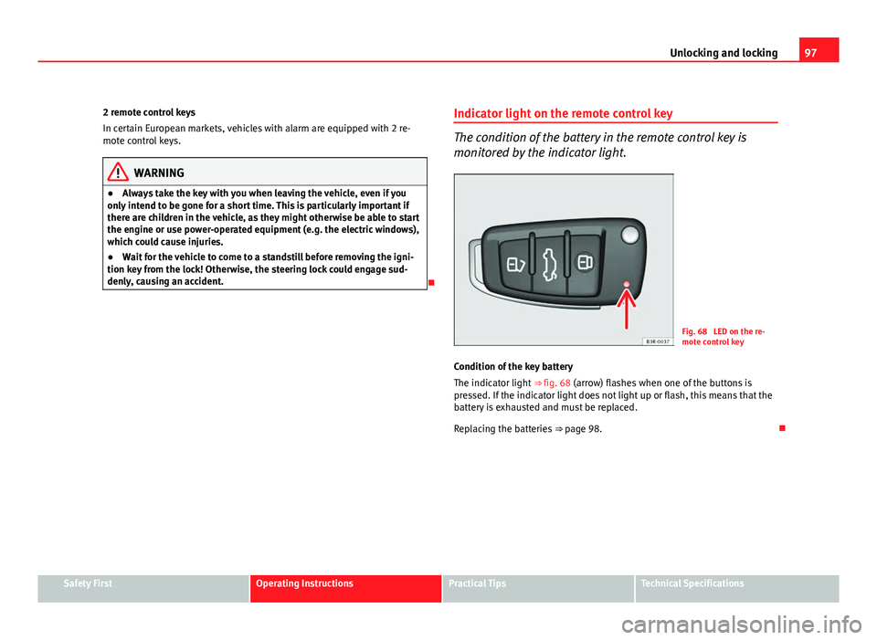
Fig. 68 LED on the re-
mote control key
Condition of the key battery
The indicator light ⇒ fig. 68 (arrow) flashes when one of the buttons is
pressed. If the indicator light does not light up or flash, this means that the
battery is exhausted and must be replaced.
Replacing the batteries ⇒ page 98.
Safety FirstOperating InstructionsPractical TipsTechnical Specifications
Page 100 of 319
98Unlocking and locking
Replacing the key battery
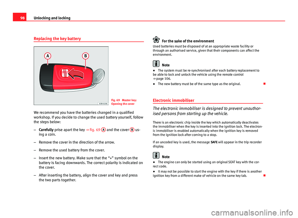
Fig. 69 Master key:
Opening the cover
We recommend you have the batteries changed in a qualified
workshop. If you decide to change the used battery yourself, follow
the steps below:
– Carefully prise apart the key ⇒ fig. 69 A
and the cover B us-
ing a coin.
– Remove the cover in the direction of the arrow.
– Remove the used battery from the cover.
– Insert the new battery. Make sure that the “+” symbol on the
battery is facing downwards. The correct polarity is indicated on
the cover.
– After inserting the battery, align the cover and key and press
the two parts together.
For the sake of the environment
Used batteries must be disposed of at an appropriate waste facility or
through an authorised service, given that their components can affect the
environment.
Note
● The system must be re-synchronised after each battery replacement to
be able to lock and unlock the vehicle using the remote control
⇒ page 106.
● The new battery must be of the same type as the original.
Electronic immobiliser
The electronic immobiliser is designed to prevent unauthor-
ised persons from starting up the vehicle.
There is an electronic chip inside the key which automatically deactivates
the immobiliser when the key is inserted into the ignition lock. The electron-
ic immobiliser is enabled automatically when the ignition key is removed
from the ignition lock after coming to a stop.
If an uncoded key is used, the message SAFE will appear in the trip recorder
display.
Note
● The engine can only be started using an original SEAT key with the cor-
rect code.
● It may not be possible to start the engine with the key if there is another
ignition key from a different make of vehicle on the same key tab.
Page 107 of 319
105
Unlocking and locking
Activating the childproof lock
– Turn the key in the direction of the arrow ⇒ fig. 77.
Deactivating the childproof lock
– Turn the key in the opposite direction of the arrow.
When the childproof lock is enabled, the inside door handle will not work
and the door can only be opened from the outside.
Remote control key Description
The remote control key will lock and unlock the vehicle with-
out having to insert the key in the lock. The following functions are available:
● Locking and unlocking the vehicle
● Unlocking the tailgate
All the turn signals will flash as confirmation when the vehicle is locked or
unlocked. Furthermore, the interior lights will automatically light up when
the vehicle is unlocked and go out when the vehicle is locked, provided that
the switches are in the courtesy light position.
The remote control transmitter and the battery are integrated into the han-
dle of the key. The receiver is in the interior of the vehicle. The maximum
range depends on different circumstances. The range is reduced when the
battery starts to lose power.
The remote control incorporates a foldaway key that can be used to manual-
ly lock or unlock the vehicle, as well as to start the engine. If the receiver has been repaired or replaced, or if a replacement key is
used, the system will need re-programming by a qualified workshop. Only
then will you be able use the remote control again.
The remote control meets all relevant authorisation requirements and has
been approved by the Federal Approvals Office for Telecommunications of
the Federal Republic of Germany. All components are marked in accordance
with the current legal requirements. This certification forms the basis for of-
ficial approval for use in other countries.
Note
● The remote control is automatically disabled when the ignition is switch-
ed on.
● The function of the remote control may be impaired by interference from
other nearby radio signals (e.g. from a mobile phone or TV transmitter) if
these are in the same frequency range.
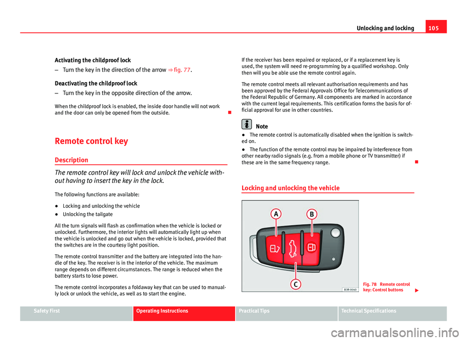
Locking and unlocking the vehicle
Fig. 78 Remote control
key: Control buttons
Safety FirstOperating InstructionsPractical TipsTechnical Specifications
Page 111 of 319
109
Unlocking and locking
WARNING
Do not leave anyone (especially children) in the vehicle if it is locked from
the outside and the anti-theft security system is enabled, as the doors
and windows cannot then be opened from the inside. Locked doors could
delay assistance in an emergency, potentially putting lives at risk.
Electric windows Controls
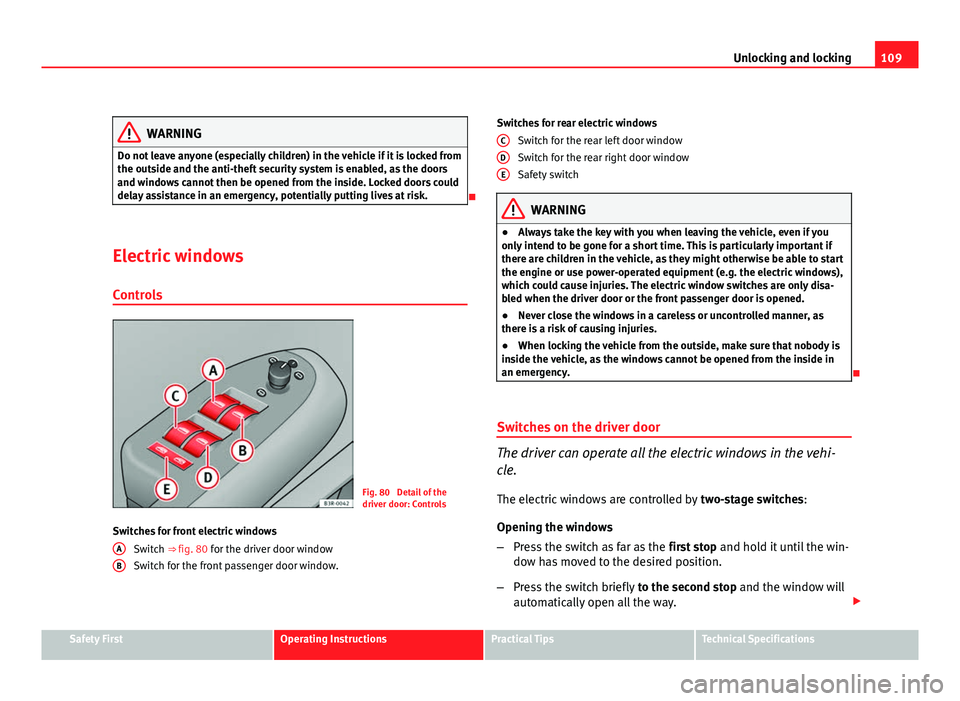
Fig. 80 Detail of the
driver door: Controls
Switches for front electric windows Switch ⇒ fig. 80 for the driver door window
Switch for the front passenger door window.
A
B
Switches for rear electric windows
Switch for the rear left door window
Switch for the rear right door window
Safety switch
WARNING
● Always take the key with you when leaving the vehicle, even if you
only intend to be gone for a short time. This is particularly important if
there are children in the vehicle, as they might otherwise be able to start
the engine or use power-operated equipment (e.g. the electric windows),
which could cause injuries. The electric window switches are only disa-
bled when the driver door or the front passenger door is opened.
● Never close the windows in a careless or uncontrolled manner, as
there is a risk of causing injuries.
● When locking the vehicle from the outside, make sure that nobody is
inside the vehicle, as the windows cannot be opened from the inside in
an emergency.
Switches on the driver door
The driver can operate all the electric windows in the vehi-
cle. The electric windows are controlled by two-stage switches:
Opening the windows
– Press the switch as far as the first stop and hold it until the win-
dow has moved to the desired position.
– Press the switch briefly to the second stop and the window will
automatically open all the way.
C
DE
Safety FirstOperating InstructionsPractical TipsTechnical Specifications
Page 130 of 319
128Lights and visibility
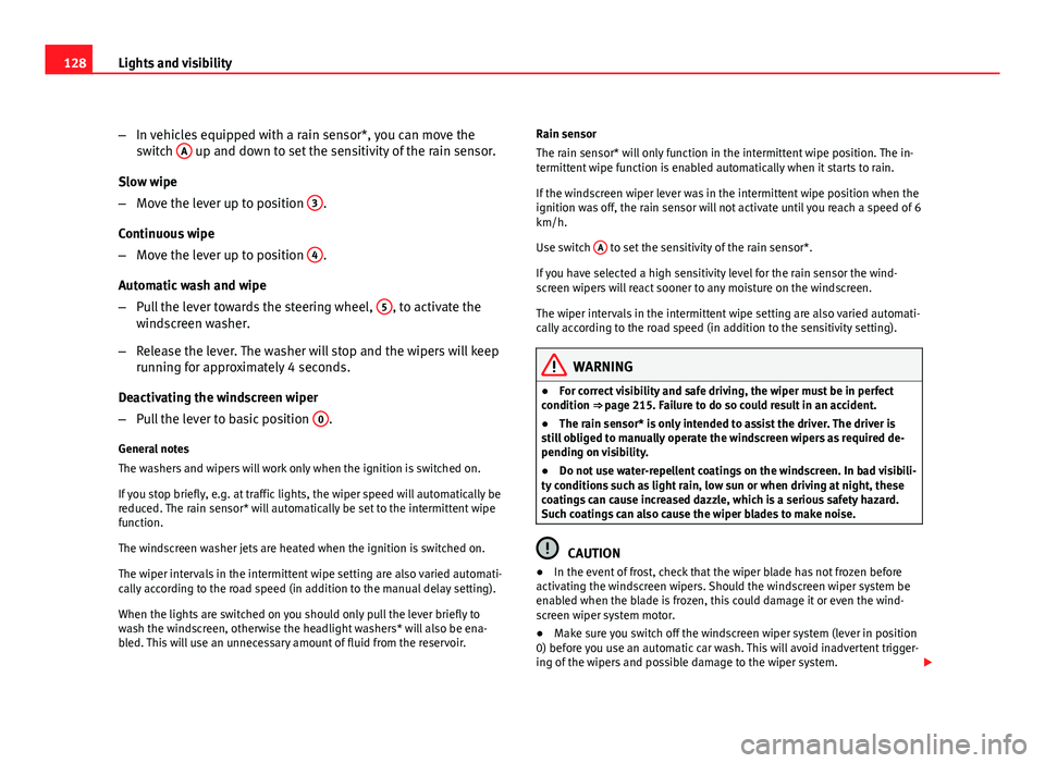
–In vehicles equipped with a rain sensor*, you can move the
switch A
up and down to set the sensitivity of the rain sensor.
Slow wipe
– Move the lever up to position 3
.
Continuous wipe
– Move the lever up to position 4
.
Automatic wash and wipe
– Pull the lever towards the steering wheel, 5
, to activate the
windscreen washer.
– Release the lever. The washer will stop and the wipers will keep
running for approximately 4 seconds.
Deactivating the windscreen wiper
– Pull the lever to basic position 0
.
General notes
The washers and wipers will work only when the ignition is switched on.
If you stop briefly, e.g. at traffic lights, the wiper speed will automatically be
reduced. The rain sensor* will automatically be set to the intermittent wipe
function.
The windscreen washer jets are heated when the ignition is switched on.
The wiper intervals in the intermittent wipe setting are also varied automati-
cally according to the road speed (in addition to the manual delay setting).
When the lights are switched on you should only pull the lever briefly to
wash the windscreen, otherwise the headlight washers* will also be ena-
bled. This will use an unnecessary amount of fluid from the reservoir. Rain sensor
The rain sensor* will only function in the intermittent wipe position. The in-
termittent wipe function is enabled automatically when it starts to rain.
If the windscreen wiper lever was in the intermittent wipe position when the
ignition was off, the rain sensor will not activate until you reach a speed of 6
km/h.
Use switch
A
to set the sensitivity of the rain sensor*.
If you have selected a high sensitivity level for the rain sensor the wind-
screen wipers will react sooner to any moisture on the windscreen.
The wiper intervals in the intermittent wipe setting are also varied automati-
cally according to the road speed (in addition to the sensitivity setting).
WARNING
● For correct visibility and safe driving, the wiper must be in perfect
condition ⇒ page 215. Failure to do so could result in an accident.
● The rain sensor* is only intended to assist the driver. The driver is
still obliged to manually operate the windscreen wipers as required de-
pending on visibility.
● Do not use water-repellent coatings on the windscreen. In bad visibili-
ty conditions such as light rain, low sun or when driving at night, these
coatings can cause increased dazzle, which is a serious safety hazard.
Such coatings can also cause the wiper blades to make noise.
CAUTION
● In the event of frost, check that the wiper blade has not frozen before
activating the windscreen wipers. Should the windscreen wiper system be
enabled when the blade is frozen, this could damage it or even the wind-
screen wiper system motor.
● Make sure you switch off the windscreen wiper system (lever in position
0) before you use an automatic car wash. This will avoid inadvertent trigger-
ing of the wipers and possible damage to the wiper system.
Page 131 of 319
129
Lights and visibility
Note
● Check that the washer fluid reservoir is full before starting a long jour-
ney. Fill the reservoir ⇒ page 233.
● Worn or dirty wiper blades can cause smearing on the glass which can
also impair the effectiveness of the rain sensor*. Check the condition of
windscreen wiper blades at regular intervals.
Rear window wiper
The windscreen wiper lever also operates the rear window
wiper and the automatic wash and wipe.
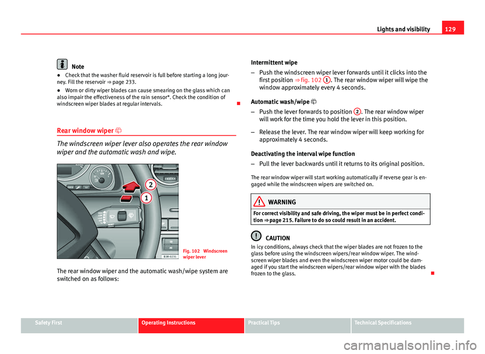
Fig. 102 Windscreen
wiper lever
The rear window wiper and the automatic wash/wipe system are
switched on as follows: Intermittent wipe
–
Push the windscreen wiper lever forwards until it clicks into the
first position ⇒ fig. 102 1
. The rear window wiper will wipe the
window approximately every 4 seconds.
Automatic wash/wipe
– Push the lever forwards to position 2
. The rear window wiper
will work for the time you hold the lever in this position.
– Release the lever. The rear window wiper will keep working for
approximately 4 seconds.
Deactivating the interval wipe function
– Pull the lever backwards until it returns to its original position.
The rear window wiper will start working automatically if reverse gear is en-
gaged while the windscreen wipers are switched on.
WARNING
For correct visibility and safe driving, the wiper must be in perfect condi-
tion ⇒ page 215. Failure to do so could result in an accident.
CAUTION
In icy conditions, always check that the wiper blades are not frozen to the
glass before using the windscreen wipers/rear window wiper. The wind-
screen wiper blades and even the windscreen wiper motor could be dam-
aged if you start the windscreen wipers/rear window wiper with the blades
frozen to the glass.
Safety FirstOperating InstructionsPractical TipsTechnical Specifications
Page 159 of 319
157
Seats and storage compartments
WARNING
● Heavy appliances or connectors (for example, adapters) which hang
down directly from the Europlug socket may damage the socket with the
resultant risk of injury.
● Ensure that appliances connected to the socket are secure to prevent
them from being thrown around the vehicle in the event of sharp braking
or an accident. This could result in severe injury or loss of life ⇒ page 16,
Storing objects.
● Never spill liquid over the socket – there is a risk of death. If any
moisture enters the socket, ensure that it is thoroughly dry before using.
● Improper use of the sockets or electrical accessories can lead to seri-
ous injuries or cause a fire, with the resultant risk of injury.
● Children must never be left alone in the vehicle with the engine run-
ning. They could cause an accident.
● Appliances connected to the socket do not behave in the same way as
when they are connected to the mains power supply. They may overheat
during use and cause injury.
● When using adapters and extension leads, the childproof safety de-
vice on the 230 volt socket is disconnected and the socket is live. Risk of
injury!.
● Never insert objects which conduct electricity, such as a needle, in
the pins of the 230 volt socket. There is a risk of death.
● Always switch off electrical appliances connected to the socket if the
inverter goes off as a result of overheating. Failure to comply could result
in injuries.
CAUTION
● The instructions for handling appliances connected to the socket must
be observed.
● If the power consumption of the appliances connected exceeds 150
watts, the socket inverter will overheat. If the temperature exceeds a certain
value, the inverter will switch off. It may also switch off if the outside tem- perature is very high, even if the power consumption is normal. The inverter
will switch on again automatically after it has cooled down. Appliances con-
nected to the socket, and which have been left switched on, will automati-
cally come back on
⇒
.
● Do not connect neon lamps to the socket. For technical reasons, these
could break down.
● Do not connect 115 volt appliances to the 230 volt power socket, as
they could be damaged. If you have any queries, please check the manufac-
turer's label for details of the power supply accepted by the appliance.
● With some adapters, for example for laptops, their built-in overload dis-
connection system prevents the equipment from switching on in the event
of an excessive start-up current. In this case, disconnect the adapter from
the power supply and try to reconnect after ten seconds.
Note
● Non-insulated equipment may cause interference to the radio or vehicle
electronics.
● The Europlug socket has a built-in childproof device and only carries live
current when the Europlug is correctly plugged in.
● Some appliances may not operate correctly in the absence of adequate
power (watts).
● In some countries this socket is 115 volts. Therefore the socket should
have a different inverter installed at the factory. You can obtain retrofit kits
from your Authorised Technical Service. Do not connect 115 Volt appliances
to the 230 Volt socket.
● The use of electrical equipment in the vicinity of the aerial in the rear
window may cause interference to the reception of stations broadcasting in
AM.
Safety FirstOperating InstructionsPractical TipsTechnical Specifications
Page 169 of 319
167
Air conditioning
Switching the temperature display from °C to °F and vice
versa
The temperature display can be switched from °C (degrees
Celsius) to °F (degrees Fahrenheit) and vice versa. – Press and hold the
button for air recirculation mode and
briefly press the plus button of the left-hand temperature selec-
tor ⇒ fig. 141.
Switching the air conditioner on/off
Switching the air conditioner off: models with an OFF button
– Press the OFF
button. The air conditioner is switched off and
the supply of air from outside the vehicle is cut off.
Switching the air conditioner off: models with a
button
– Keep pressing the -
button for the blower until the display seg-
ment is empty. The air conditioner is switched off and the sup-
ply of air from outside the vehicle is cut off.
Switching the air conditioner on: models with an OFF
button
– Press the OFF
button again, or
– Press the AUTO
button or
– Press one of the air distribution buttons
, or .
Switching the air conditioner on: models with a
button
– Press the +
button for the blower, or –
Press the AUTO
button or
– Press one of the air distribution buttons
, or .
The air conditioner also starts to operate if one of the blower or temperature
selector buttons is pressed.
Blower speed -
+
The automatically selected blower speed can be reduced or
increased manually.
– Press the -
and + buttons in the centre of the control panel
⇒ fig. 141 to set the blower to the desired speed (and regulate
the volume of air delivery).
The air conditioner system automatically regulates the blower speed accord-
ing to the interior temperature. However, you can also adjust the air delivery
manually. The current blower setting is illustrated by a bar in the middle dis-
play (above the buttons).
Automatic change of passenger temperature
In order to automatically set the passenger temperature like the driver tem-
perature, press the AUTO button on the driver side for 2 seconds approxi-
mately. In order to automatically set the driver temperature like the passen-
ger temperature, press the AUTO
button on the passenger side for 2 sec-
onds approximately.
Safety FirstOperating InstructionsPractical TipsTechnical Specifications
Page 171 of 319
169
Air conditioning
Air directed to windows
This setting directs all the air to outlets 1 and 2. Unlike in setting , the
volume of air delivery remains the same.
Air to the driver/front passenger
All the air comes from outlets 3 and 4 in the dash panel and from the rear of
the centre console.
Air to the footwells
Most of the air emerges from outlets 5 and the outlets under the front seats.
Some of the air will also be issued from outlets 3 and 4.
Note
In all of the above air distribution settings, a small amount of air will still
come from the other outlets.
Economical use of the air conditioner
Economical use of the air conditioner will help save fuel.
Engine power is reduced and fuel consumption increases when the
air conditioner is in cooling mode. To ensure that the system is on-
ly switched on when it is really necessary, please note the follow-
ing points:
– Select ECON mode if you wish to save fuel.
– Select ECON mode if you decide to open the windows or sun-
roof* while driving.
– If the vehicle has heated up after standing in the sun, open the
windows and doors for a short time to cool the vehicle.
For the sake of the environment
By saving fuel you also reduce the amount of pollutants emitted from your
vehicle.
Key settings
When the ignition is switched on, the air conditioner set-
tings assigned to the key are selected automatically.
The air conditioner settings selected are automatically stored and assigned
to the key in use. When the vehicle is started, the air conditioner automati-
cally selects the settings assigned to the key. Hence, every driver automati-
cally obtains his/her preferred settings without having to select them man-
ually.
Note
Should another driver use the key and enter other settings, the previous
settings will be deleted.
Solar-powered blower/sunroof*
If the vehicle is parked in sufficiently strong sunlight, the
blower will operate in solar-powered mode when the igni-
tion is switched off.
After the ignition is switched off, the blower is supplied with electrical pow-
er from the sunroof. Please ensure that outlets 3 and 4 are open ⇒ fig. 143
to ensure the best possible ventilation.
The blower only works when the sunroof is closed or tilted open at the rear.
Safety FirstOperating InstructionsPractical TipsTechnical Specifications
Page 174 of 319
172Driving
The Electronic Stability Programme (ESP) contains the electronic differential
lock (EDL) and the traction control system (TCS). The ESP function works to-
gether with the ABS. If a fault in the ABS occurs, both warning lamps light
up, but if the ESP fails, only the ESP warning lamp lights up.
The ESP is started automatically when the engine is started.
The ESP switch deactivates both TCS and ESP functions. The ESP, in spite of
being deactivated, will always self-connect when necessary if brakes are be-
ing used.
The TCS can be deactivated when in cases where wheel sliding is desirable.
For example:
● When driving with snow chains.
● When driving in deep snow or on loose surfaces.
● When the vehicle is stuck, to rock it backwards and forwards.
Next, the button should be pressed to reactivate the TCS.
When does the lamp light up or flash
●
On switching the ignition on, it lights up for about two seconds to carry
out a function control.
● The warning lamp will start flashing when the vehicle is moving if the
ESP or the TCS is activated.
● It will light up continuously if there is a malfunction in the ESP.
WARNING
● The Electronic Stability Programme (ESP) cannot defy the laws of
physics. This should be kept in mind, particularly on slippery and wet
roads and when towing a trailer.
● Always adapt your driving style to suit the condition of the roads and
the traffic situation. Do not let the extra safety afforded by ESP tempt you
into taking any risks when driving, as this can cause accidents.
● Please refer to the corresponding warning notes on ESP in
⇒ page 190, Intelligent technology.
Ignition lock Ignition key positions
The ignition key is used to start and stop the engine.
Fig. 147 Ignition key po-
sitions