cooling Seat Exeo ST 2011 Owner's manual
[x] Cancel search | Manufacturer: SEAT, Model Year: 2011, Model line: Exeo ST, Model: Seat Exeo ST 2011Pages: 319, PDF Size: 5.12 MB
Page 6 of 319
Trailer towing . . . . . . . . . . . . . . . . . . . . . . . . . . . . . . 201
Trailer towing . . . . . . . . . . . . . . . . . . . . . . . . . . . . . 201
Removable towing bracket . . . . . . . . . . . . . . . . . . 204
Vehicle maintenance and cleaning . . . . . . . . . 211
General notes . . . . . . . . . . . . . . . . . . . . . . . . . . . . 211
Care of the vehicle exterior . . . . . . . . . . . . . . . . . . 212
Vehicle interior maintenance . . . . . . . . . . . . . . . . 217
Accessories, parts replacement and
modifications . . . . . . . . . . . . . . . . . . . . . . . . . . . . . 220
Accessories and spare parts . . . . . . . . . . . . . . . . 220
Technical modifications . . . . . . . . . . . . . . . . . . . . 220
Mobile phones and two-way radios . . . . . . . . . . . 221
Athermic windscreen* . . . . . . . . . . . . . . . . . . . . . 221
Checking and refilling levels . . . . . . . . . . . . . . . 222
Refuelling . . . . . . . . . . . . . . . . . . . . . . . . . . . . . . . 222
Petrol . . . . . . . . . . . . . . . . . . . . . . . . . . . . . . . . . . . 223
Diesel . . . . . . . . . . . . . . . . . . . . . . . . . . . . . . . . . . . 224
Bonnet . . . . . . . . . . . . . . . . . . . . . . . . . . . . . . . . . . 225
Engine oil . . . . . . . . . . . . . . . . . . . . . . . . . . . . . . . . 227
Cooling system . . . . . . . . . . . . . . . . . . . . . . . . . . . 230
Washer fluid and windscreen wiper blades . . . . 233
Brake fluid . . . . . . . . . . . . . . . . . . . . . . . . . . . . . . . 236
Vehicle battery . . . . . . . . . . . . . . . . . . . . . . . . . . . 237
Wheels and tyres . . . . . . . . . . . . . . . . . . . . . . . . . . 241
Wheels . . . . . . . . . . . . . . . . . . . . . . . . . . . . . . . . . . 241
If and when . . . . . . . . . . . . . . . . . . . . . . . . . . . . . . . 251
Tools, tyre repair kit and spare wheel . . . . . . . . . 251
Changing a wheel . . . . . . . . . . . . . . . . . . . . . . . . . 254
Tyre repair* (Tyre-Mobility-System) . . . . . . . . . . . 258
Fuses . . . . . . . . . . . . . . . . . . . . . . . . . . . . . . . . . . . 262
Bulbs . . . . . . . . . . . . . . . . . . . . . . . . . . . . . . . . . . . 264
Changing bulbs. Halogen headlights . . . . . . . . . 265
Changing bulbs. Bi-Xenon AFS headlights . . . . . 271
Changing tail light bulbs (on side panel) . . . . . . 275
Changing tail light bulbs (on tailgate) . . . . . . . . . 280
Side turn signals . . . . . . . . . . . . . . . . . . . . . . . . . . 283 Luggage compartment lights . . . . . . . . . . . . . . . . 284
Registration light . . . . . . . . . . . . . . . . . . . . . . . . . . 285
Sun visor light . . . . . . . . . . . . . . . . . . . . . . . . . . . . 286
Jump-starting . . . . . . . . . . . . . . . . . . . . . . . . . . . . . 286
Towing and tow-starting . . . . . . . . . . . . . . . . . . . . 289
Technical Specifications . . . . . . . . . . . 292
Description of specifications . . . . . . . . . . . . . . . 292
Important information . . . . . . . . . . . . . . . . . . . . . 292
Information on fuel consumption . . . . . . . . . . . . 294
Towing a trailer . . . . . . . . . . . . . . . . . . . . . . . . . . . 294
Wheels . . . . . . . . . . . . . . . . . . . . . . . . . . . . . . . . . . 295
Technical specifications . . . . . . . . . . . . . . . . . . . . 296
Engine specifications . . . . . . . . . . . . . . . . . . . . . . 296
Dimensions and capacities . . . . . . . . . . . . . . . . . 305
Index . . . . . . . . . . . . . . . . . . . . . . . . . . . . . . . . . . . 307
4Table of Contents
Page 62 of 319

60Cockpit
CHECK button . . . . . . . . . . . . . . . . . . . . . . . . . . . . . . . . . . . . . . . . . . . . . 64
Call-up button for service indicator . . . . . . . . . . . . . . . . . . . . . . . . .74
Reset button for trip recorder . . . . . . . . . . . . . . . . . . . . . . . . . . . . . . 63
Coolant temperature gauge
Fig. 38 Engine coolant
temperature gauge
The coolant temperature gauge ⇒ fig. 38 only works when the ignition is
switched on. In order to avoid engine damage, please read the following
notes for the different temperature ranges.
Cold temperature A
If the needle is still on the left of the dial, this indicates that the engine has
not yet reached operating temperature. Avoid high revs and heavy accelera-
tion and do not make the engine work hard.
Normal temperature B
In normal operations, the needle will settle somewhere in the centre of the
dial once the engine has reached running temperature. The temperature
may also rise when the engine is working hard, especially at high outside8
910
temperatures. This is no cause for concern, provided the warning lamp
does not light up in the instrument panel.
Warning temperature C
If the symbol
flashes in the display, this means that either the coolant
temperature is too high or the coolant level is too low ⇒ page 78.
WARNING
● Before opening the bonnet and checking the coolant level, observe
the warning information ⇒ page 226.
● Never open the bonnet when steam or coolant is being released from
it. This could lead to burns. Wait until you can no longer see or hear es-
caping steam or coolant.
CAUTION
Accessories in front of the air inlet reduce the cooling effect of the coolant.
At high outside temperatures and high engine loads, there is a risk of the
engine overheating.
Page 80 of 319
78Cockpit
WARNING
● Before opening the bonnet and checking the brake fluid level, ob-
serve the warning information in ⇒ page 226, Work in the engine com-
partment.
● If the brake fluid level in the reservoir is too low, this could result in
an accident. Do not drive on! Obtain technical assistance.
● If the brake warning lamp lights up together with the ABS warning
lamp, this can mean that there is a fault in the ABS control function. As a
result, the rear wheels can lock relatively easily when braking. Under cer-
tain circumstances, the rear of the vehicle could suddenly sway from side
to side, with the subsequent danger of skidding. Drive carefully to the
nearest specialised workshop and have the fault repaired.
Fault in the cooling system
Faults in the cooling system must be repaired immediately.
If the symbol flashes in the display, this means that either the
coolant temperature is too high or the coolant level is too low. The
following message will appear in the display together with the
symbol:
Switch off engine and check coolant level
– Stop the vehicle.
– Switch the engine off.
– Check the coolant level ⇒ page 231.
– Add more coolant if necessary ⇒ page 232.
– Wait for the symbol to go out before driving on. –
Obtain professional assistance if necessary.
If the coolant level is correct, the overheating may be caused by a malfunc-
tion of the radiator fan.
If the alternator warning lamp lights up as well ⇒ page 69, it is possible that
the drive belt has broken.
CAUTION
Do not drive on if the symbol has come on to indicate a fault in the cool-
ing system, otherwise there is a risk of engine damage.
Engine oil pressure too low
If the engine oil pressure is too low the fault must be re-
paired immediately.
If the symbol flashes in the display, the oil pressure is too low.
The following message will appear in the display together with the
symbol:
Switch off engine, check oil level
– Stop the vehicle.
– Switch the engine off.
– Check the engine oil level ⇒ page 229.
– Obtain professional assistance if necessary.
Engine oil level too low
If the engine oil level is too low, add more oil ⇒ page 230.
Page 163 of 319
161
Air conditioning
Air conditioning 2C-Climatronic
Description
The air conditioner is designed to automatically keep the
passenger compartment at the temperature you find most
comfortable at all times of the year. Recommended settings:
– Set the temperature to 22 °C (71 °F).
– Press the AUTO
⇒ fig. 141 button.
The following setting quickly provides a comfortable temperature inside the
vehicle. We therefore recommend you do not modify the setting unless you
find this temperature uncomfortable or where circumstances require as
such.
The air conditioner provides heating and ventilation and also cools and de-
humidifies the air inside the vehicle.
The air conditioner is fully automatic and will constantly maintain the tem-
perature which has been set. To achieve this, the temperature of the air sup-
plied to the interior, the blower speed (volume of air delivery) and the air
distribution are regulated automatically. The system also takes solar radia-
tion into account and, therefore, no subsequent manual readjustments are
required. Therefore, automatic mode ⇒ page 164 should be used for the
comfort of all the passengers in virtually all conditions throughout the year.
Please note the following points: The humidity of the air is automatically reduced when the system cools the
interior of the vehicle. This helps to prevent condensation on the windows.
If the humidity and temperature outside the vehicle are high,
condensation
can drip off the evaporator in the air cooling system and form a pool under-
neath the vehicle. This is normal and does not indicate a leak.
If the outside temperature is low, the blower normally only switches to a
higher speed once the coolant has warmed up sufficiently (this does not ap-
ply to the defrost setting).
In order to achieve maximum engine power, the air conditioner compressor
is temporarily switched off when pulling away from standstill with full throt-
tle.
The compressor also switches off if the coolant temperature is excessively
high to ensure adequate engine cooling under extreme loads.
Pollution filter
The pollution filter (a combined particulate filter and activated charcoal fil-
ter) serves as a barrier against impurities in the outside air, including dust
and pollen.
For the air conditioner to work with maximum efficiency, the pollution filter
element must be replaced at the intervals specified in the Service Plan.
If the vehicle is driven in areas with a high level of air pollution and the filter
is no longer fully effective, it may be necessary to change the filter element
more frequently.
Safety FirstOperating InstructionsPractical TipsTechnical Specifications
Page 164 of 319
162Air conditioning
CAUTION
● If you suspect that the air conditioner system is damaged, switch over to
ECON mode to prevent further damage and have the system checked by a
qualified workshop.
● Repairs to the air conditioner require specialist knowledge and special
tools. For this reason, please contact a qualified workshop if the system is
not working properly.
Note
● Keep the air intake slots in front of the windscreen clear of snow, ice and
leaves to ensure unimpaired heating and cooling and to prevent the win-
dows misting over.
● The air from the outlets flows through the passenger compartment and
out through the slots below the rear window. Therefore, do not cover these
slots with items of clothing or other objects.
● The air conditioner operates most effectively with the windows and the
sliding/tilting sunroof* closed. However, if the vehicle has heated up after
standing in the sun for some time, the air inside can be cooled more quickly
by opening the windows briefly.
Page 165 of 319
163
Air conditioning
Controls
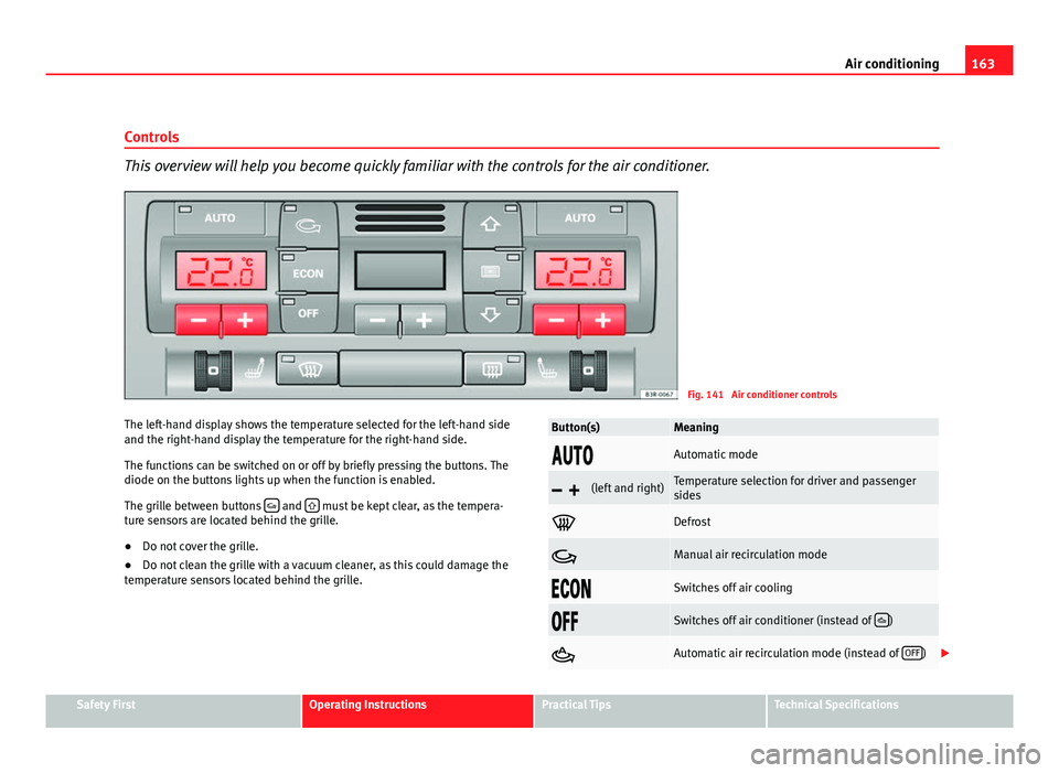
This overview will help you become quickly familiar with the controls for the air conditioner.
Fig. 141 Air conditioner controls
The left-hand display shows the temperature selected for the left-hand side
and the right-hand display the temperature for the right-hand side.
The functions can be switched on or off by briefly pressing the buttons. The
diode on the buttons lights up when the function is enabled.
The grille between buttons
and must be kept clear, as the tempera-
ture sensors are located behind the grille.
● Do not cover the grille.
● Do not clean the grille with a vacuum cleaner, as this could damage the
temperature sensors located behind the grille.
Button(s)Meaning
Automatic mode
(left and right)Temperature selection for driver and passenger
sides
Defrost
Manual air recirculation mode
Switches off air cooling
Switches off air conditioner (instead of )
Automatic air recirculation mode (instead of OFF)
Safety FirstOperating InstructionsPractical TipsTechnical Specifications
Page 166 of 319
164Air conditioning
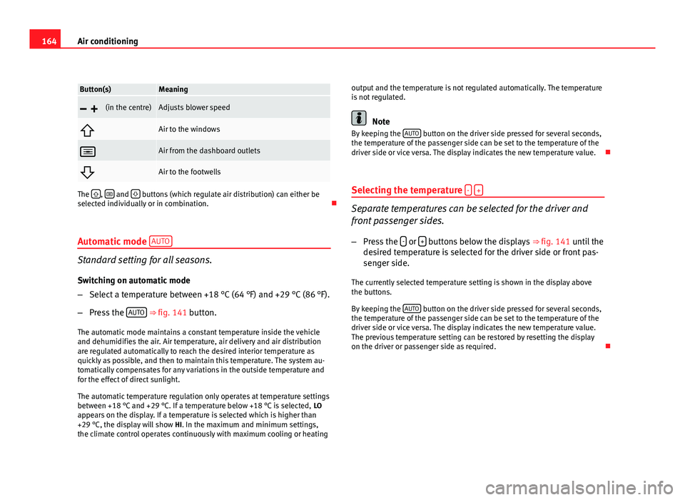
Button(s)Meaning
(in the centre)Adjusts blower speed
Air to the windows
Air from the dashboard outlets
Air to the footwells
The , and buttons (which regulate air distribution) can either be
selected individually or in combination.
Automatic mode AUTO
Standard setting for all seasons.
Switching on automatic mode
– Select a temperature between +18 °C (64 °F) and +29 °C (86 °F).
– Press the AUTO
⇒
fig. 141 button.
The automatic mode maintains a constant temperature inside the vehicle
and dehumidifies the air. Air temperature, air delivery and air distribution
are regulated automatically to reach the desired interior temperature as
quickly as possible, and then to maintain this temperature. The system au-
tomatically compensates for any variations in the outside temperature and
for the effect of direct sunlight.
The automatic temperature regulation only operates at temperature settings
between +18 °C and +29 °C. If a temperature below +18 °C is selected, LO
appears on the display. If a temperature is selected which is higher than
+29 °C, the display will show HI. In the maximum and minimum settings,
the climate control operates continuously with maximum cooling or heating output and the temperature is not regulated automatically. The temperature
is not regulated.
Note
By keeping the AUTO button on the driver side pressed for several seconds,
the temperature of the passenger side can be set to the temperature of the
driver side or vice versa. The display indicates the new temperature value.
Selecting the temperature -
+
Separate temperatures can be selected for the driver and
front passenger sides.
– Press the -
or + buttons below the displays
⇒ fig. 141 until the
desired temperature is selected for the driver side or front pas-
senger side.
The currently selected temperature setting is shown in the display above
the buttons.
By keeping the AUTO
button on the driver side pressed for several seconds,
the temperature of the passenger side can be set to the temperature of the
driver side or vice versa. The display indicates the new temperature value.
The previous temperature setting can be restored by resetting the display
on the driver or passenger side as required.
Page 167 of 319
165
Air conditioning
Defrosting
The windscreen and side windows are defrosted or demisted
as quickly as possible.
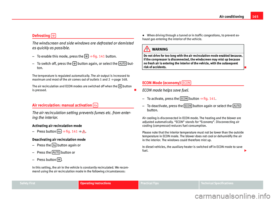
– To enable this mode, press the
⇒
fig. 141 button.
– To switch off, press the
button again, or select the AUTO but-
ton.
The temperature is regulated automatically. The air output is increased to
maximum and most of the air comes out of outlets 1 and 2 ⇒ page 168.
The air recirculation and ECON modes are switched off when the
button
is pressed.
Air recirculation: manual activation
The air recirculation setting prevents fumes etc. from enter-
ing the interior.
Activating air recirculation mode
– Press button
⇒ fig. 141 ⇒ .
Deactivating air recirculation mode
– Press the
button again or
– Press the AUTO
button or
– Press button
.
In this setting, the air in the vehicle is constantly recirculated. We recom-
mend using the air recirculation mode in the following circumstances: ●
When driving through a tunnel or in traffic congestions, to prevent ex-
haust gas entering the interior of the vehicle.
WARNING
Do not drive for too long with the air recirculation mode enabled because,
if the compressor is disconnected, the windscreen may mist up because
no fresh air is entering the interior of the vehicle, with the subsequent
risk of accidents.
ECON Mode (economy) ECON
ECON mode helps save fuel.
– To activate, press the ECON
button ⇒ fig. 141.
– To deactivate, press the ECON
button again or select the AUTObutton.
Air cooling is disconnected in ECON mode. The heating and the blower are
adjusted automatically. “ECON” stands for “Economy”. Disconnecting air
cooling (compressor) reduces fuel consumption.
Please note that the interior temperature must not be lower than the outside
temperature in ECON mode. The blower does not cool or dehumidify the air
in the interior. The windows could therefore mist up.
In diesel vehicles, the auxiliary heater is switched off in ECON mode to save
fuel.
Safety FirstOperating InstructionsPractical TipsTechnical Specifications
Page 170 of 319
168Air conditioning
Air outlets
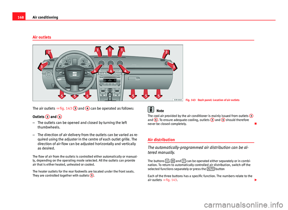
Fig. 143 Dash panel: Location of air outlets
The air outlets ⇒ fig. 143 3
and 4 can be operated as follows:
Outlets 3
and 4
–
The outlets can be opened and closed by turning the left
thumbwheels.
– The direction of air delivery from the outlets can be varied as re-
quired using the adjuster in the centre of each outlet grille. The
direction of air flow can be adjusted horizontally and vertically
as desired.
The flow of air from the outlets is controlled either automatically or manual-
ly, depending on the operating mode selected. All the outlets can provide
air that is either heated, unheated or cooled.
The heater outlets for the rear footwells are located under the front seats.
They are controlled together with outlets 5
.
Note
The cool air provided by the air conditioner is mainly issued from outlets 3
and 4. To ensure adequate cooling, outlets 3 and 4 should therefore
never be closed completely.
Air distribution
The automatically-programmed air distribution can be al-
tered manually.
The buttons
, and can be operated either separately or in combi-
nation. To return to automatically controlled air distribution, switch off the
selected functions separately or press the AUTO
button
Each of the three buttons has a specific function. The numbers relate to the
air outlets ⇒ fig. 143.
Page 171 of 319
169
Air conditioning
Air directed to windows
This setting directs all the air to outlets 1 and 2. Unlike in setting , the
volume of air delivery remains the same.
Air to the driver/front passenger
All the air comes from outlets 3 and 4 in the dash panel and from the rear of
the centre console.
Air to the footwells
Most of the air emerges from outlets 5 and the outlets under the front seats.
Some of the air will also be issued from outlets 3 and 4.
Note
In all of the above air distribution settings, a small amount of air will still
come from the other outlets.
Economical use of the air conditioner
Economical use of the air conditioner will help save fuel.
Engine power is reduced and fuel consumption increases when the
air conditioner is in cooling mode. To ensure that the system is on-
ly switched on when it is really necessary, please note the follow-
ing points:
– Select ECON mode if you wish to save fuel.
– Select ECON mode if you decide to open the windows or sun-
roof* while driving.
– If the vehicle has heated up after standing in the sun, open the
windows and doors for a short time to cool the vehicle.
For the sake of the environment
By saving fuel you also reduce the amount of pollutants emitted from your
vehicle.
Key settings
When the ignition is switched on, the air conditioner set-
tings assigned to the key are selected automatically.
The air conditioner settings selected are automatically stored and assigned
to the key in use. When the vehicle is started, the air conditioner automati-
cally selects the settings assigned to the key. Hence, every driver automati-
cally obtains his/her preferred settings without having to select them man-
ually.
Note
Should another driver use the key and enter other settings, the previous
settings will be deleted.
Solar-powered blower/sunroof*
If the vehicle is parked in sufficiently strong sunlight, the
blower will operate in solar-powered mode when the igni-
tion is switched off.
After the ignition is switched off, the blower is supplied with electrical pow-
er from the sunroof. Please ensure that outlets 3 and 4 are open ⇒ fig. 143
to ensure the best possible ventilation.
The blower only works when the sunroof is closed or tilted open at the rear.
Safety FirstOperating InstructionsPractical TipsTechnical Specifications