fuel Seat Exeo ST 2011 Owner's manual
[x] Cancel search | Manufacturer: SEAT, Model Year: 2011, Model line: Exeo ST, Model: Seat Exeo ST 2011Pages: 319, PDF Size: 5.12 MB
Page 6 of 319
Trailer towing . . . . . . . . . . . . . . . . . . . . . . . . . . . . . . 201
Trailer towing . . . . . . . . . . . . . . . . . . . . . . . . . . . . . 201
Removable towing bracket . . . . . . . . . . . . . . . . . . 204
Vehicle maintenance and cleaning . . . . . . . . . 211
General notes . . . . . . . . . . . . . . . . . . . . . . . . . . . . 211
Care of the vehicle exterior . . . . . . . . . . . . . . . . . . 212
Vehicle interior maintenance . . . . . . . . . . . . . . . . 217
Accessories, parts replacement and
modifications . . . . . . . . . . . . . . . . . . . . . . . . . . . . . 220
Accessories and spare parts . . . . . . . . . . . . . . . . 220
Technical modifications . . . . . . . . . . . . . . . . . . . . 220
Mobile phones and two-way radios . . . . . . . . . . . 221
Athermic windscreen* . . . . . . . . . . . . . . . . . . . . . 221
Checking and refilling levels . . . . . . . . . . . . . . . 222
Refuelling . . . . . . . . . . . . . . . . . . . . . . . . . . . . . . . 222
Petrol . . . . . . . . . . . . . . . . . . . . . . . . . . . . . . . . . . . 223
Diesel . . . . . . . . . . . . . . . . . . . . . . . . . . . . . . . . . . . 224
Bonnet . . . . . . . . . . . . . . . . . . . . . . . . . . . . . . . . . . 225
Engine oil . . . . . . . . . . . . . . . . . . . . . . . . . . . . . . . . 227
Cooling system . . . . . . . . . . . . . . . . . . . . . . . . . . . 230
Washer fluid and windscreen wiper blades . . . . 233
Brake fluid . . . . . . . . . . . . . . . . . . . . . . . . . . . . . . . 236
Vehicle battery . . . . . . . . . . . . . . . . . . . . . . . . . . . 237
Wheels and tyres . . . . . . . . . . . . . . . . . . . . . . . . . . 241
Wheels . . . . . . . . . . . . . . . . . . . . . . . . . . . . . . . . . . 241
If and when . . . . . . . . . . . . . . . . . . . . . . . . . . . . . . . 251
Tools, tyre repair kit and spare wheel . . . . . . . . . 251
Changing a wheel . . . . . . . . . . . . . . . . . . . . . . . . . 254
Tyre repair* (Tyre-Mobility-System) . . . . . . . . . . . 258
Fuses . . . . . . . . . . . . . . . . . . . . . . . . . . . . . . . . . . . 262
Bulbs . . . . . . . . . . . . . . . . . . . . . . . . . . . . . . . . . . . 264
Changing bulbs. Halogen headlights . . . . . . . . . 265
Changing bulbs. Bi-Xenon AFS headlights . . . . . 271
Changing tail light bulbs (on side panel) . . . . . . 275
Changing tail light bulbs (on tailgate) . . . . . . . . . 280
Side turn signals . . . . . . . . . . . . . . . . . . . . . . . . . . 283 Luggage compartment lights . . . . . . . . . . . . . . . . 284
Registration light . . . . . . . . . . . . . . . . . . . . . . . . . . 285
Sun visor light . . . . . . . . . . . . . . . . . . . . . . . . . . . . 286
Jump-starting . . . . . . . . . . . . . . . . . . . . . . . . . . . . . 286
Towing and tow-starting . . . . . . . . . . . . . . . . . . . . 289
Technical Specifications . . . . . . . . . . . 292
Description of specifications . . . . . . . . . . . . . . . 292
Important information . . . . . . . . . . . . . . . . . . . . . 292
Information on fuel consumption . . . . . . . . . . . . 294
Towing a trailer . . . . . . . . . . . . . . . . . . . . . . . . . . . 294
Wheels . . . . . . . . . . . . . . . . . . . . . . . . . . . . . . . . . . 295
Technical specifications . . . . . . . . . . . . . . . . . . . . 296
Engine specifications . . . . . . . . . . . . . . . . . . . . . . 296
Dimensions and capacities . . . . . . . . . . . . . . . . . 305
Index . . . . . . . . . . . . . . . . . . . . . . . . . . . . . . . . . . . 307
4Table of Contents
Page 61 of 319

59
Cockpit
Instruments Instrument panel overview
The instrument panel is the driver's information centre.
Fig. 37 Overview of instrument panel Coolant temperature gauge . . . . . . . . . . . . . . . . . . . . . . . . . . . . . . . . 60
Rev counter incorporating digital clock and date . . . . . . . . . . . .61, 61
Warning and indicator lamps . . . . . . . . . . . . . . . . . . . . . . . . . . . . . . 65
Speedometer (incorporating odometer display) . . . . . . . . . . . . .63
Fuel gauge . . . . . . . . . . . . . . . . . . . . . . . . . . . . . . . . . . . . . . . . . . . . . . . . 63
1
2345
Adjuster buttons for
–
Digital clock and date . . . . . . . . . . . . . . . . . . . . . . . . . . . . . . . . . . . 61
– Instrument lighting . . . . . . . . . . . . . . . . . . . . . . . . . . . . . . . . . . . . . 62
Digital display with
– Service interval display . . . . . . . . . . . . . . . . . . . . . . . . . . . . . . . . . 74
– Driver information system . . . . . . . . . . . . . . . . . . . . . . . . . . . . . . . 71
6
7
Safety FirstOperating InstructionsPractical TipsTechnical Specifications
Page 63 of 319
61
Cockpit
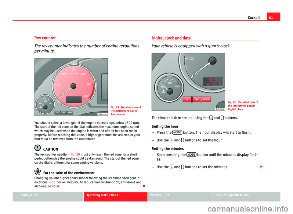
Rev counter
The rev counter indicates the number of engine revolutions
per minute.
Fig. 39 Detailed view of
the instrument panel:
Rev counter
You should select a lower gear if the engine speed drops below 1500 rpm.
The start of the red zone on the dial indicates the maximum engine speed
which may be used when the engine is warm and after it has been run in
properly. Before reaching this zone, a higher gear must be selected or your
foot must be removed from the accelerator.
CAUTION
The rev counter needle ⇒ fig. 39 must only reach the red zone for a short
period, otherwise the engine could be damaged. The start of the red zone
on the dial is different for some engine versions.
For the sake of the environment
Changing up into higher gears sooner following the recommended gear in-
dications ⇒ fig. 50 will help you to reduce fuel consumption, emissions and
also engine noise. Digital clock and date
Your vehicle is equipped with a quartz clock.
Fig. 40 Detailed view of
the instrument panel:
Digital clock
The time and date are set using the +
and - buttons.
Setting the hour
– Press the MODE
button. The hour display will start to flash.
– Use the +
and - buttons to set the hour.
Setting the minutes
– Keep pressing the MODE
button until the minutes display flash-
es.
– Use the +
and - buttons to set the minutes.
Safety FirstOperating InstructionsPractical TipsTechnical Specifications
Page 65 of 319
63
Cockpit
Speedometer with odometer
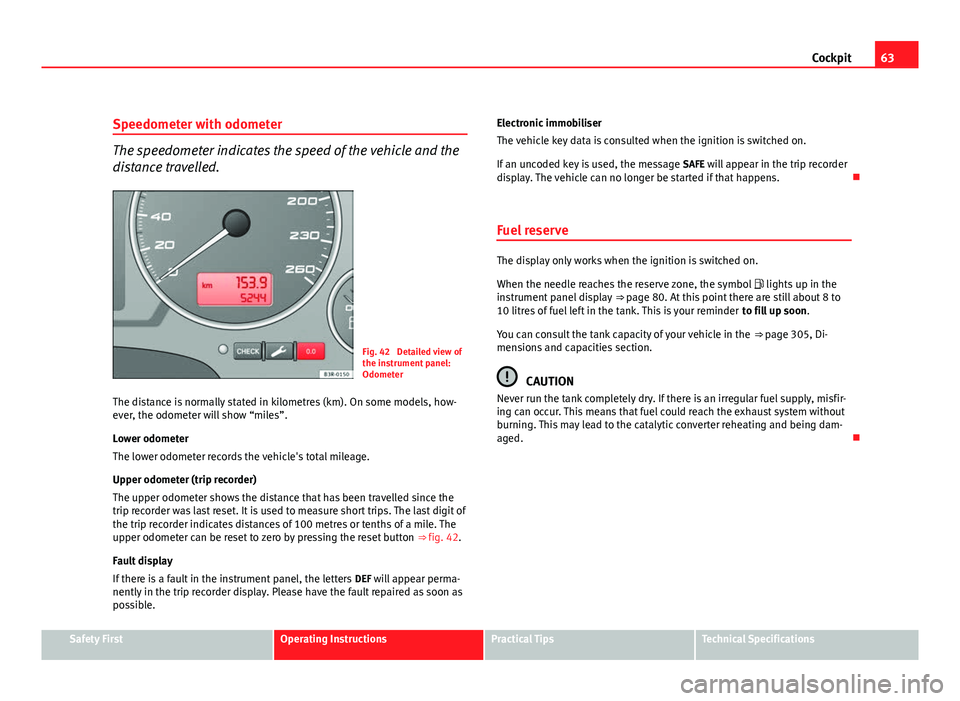
The speedometer indicates the speed of the vehicle and the
distance travelled.
Fig. 42 Detailed view of
the instrument panel:
Odometer
The distance is normally stated in kilometres (km). On some models, how-
ever, the odometer will show “miles”.
Lower odometer
The lower odometer records the vehicle's total mileage.
Upper odometer (trip recorder)
The upper odometer shows the distance that has been travelled since the
trip recorder was last reset. It is used to measure short trips. The last digit of
the trip recorder indicates distances of 100 metres or tenths of a mile. The
upper odometer can be reset to zero by pressing the reset button ⇒ fig. 42.
Fault display
If there is a fault in the instrument panel, the letters DEF will appear perma-
nently in the trip recorder display. Please have the fault repaired as soon as
possible. Electronic immobiliser
The vehicle key data is consulted when the ignition is switched on.
If an uncoded key is used, the message
SAFE will appear in the trip recorder
display. The vehicle can no longer be started if that happens.
Fuel reserve
The display only works when the ignition is switched on.
When the needle reaches the reserve zone, the symbol lights up in the
instrument panel display ⇒ page 80. At this point there are still about 8 to
10 litres of fuel left in the tank. This is your reminder to fill up soon.
You can consult the tank capacity of your vehicle in the ⇒ page 305, Di-
mensions and capacities section.
CAUTION
Never run the tank completely dry. If there is an irregular fuel supply, misfir-
ing can occur. This means that fuel could reach the exhaust system without
burning. This may lead to the catalytic converter reheating and being dam-
aged.
Safety FirstOperating InstructionsPractical TipsTechnical Specifications
Page 75 of 319
73
Cockpit
Note
When the display shows route guidance instructions from the navigation
system, the outside temperature appears in the second line of the radio dis-
play.
Gear display*
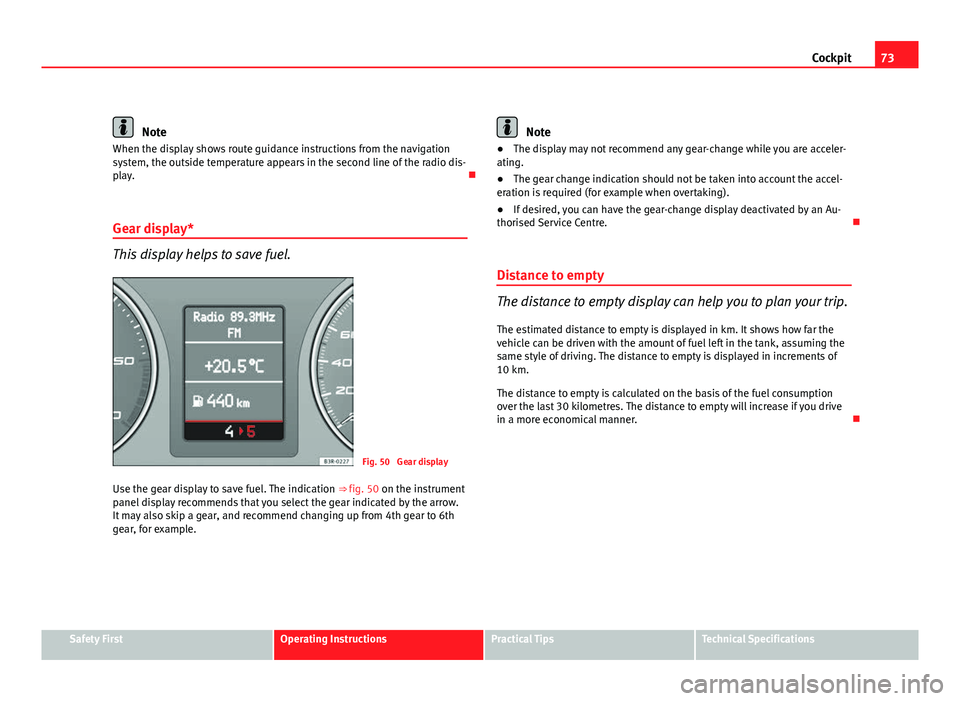
This display helps to save fuel.
Fig. 50 Gear display
Use the gear display to save fuel. The indication ⇒ fig. 50 on the instrument
panel display recommends that you select the gear indicated by the arrow.
It may also skip a gear, and recommend changing up from 4th gear to 6th
gear, for example.
Note
● The display may not recommend any gear-change while you are acceler-
ating.
● The gear change indication should not be taken into account the accel-
eration is required (for example when overtaking).
● If desired, you can have the gear-change display deactivated by an Au-
thorised Service Centre.
Distance to empty
The distance to empty display can help you to plan your trip.
The estimated distance to empty is displayed in km. It shows how far the
vehicle can be driven with the amount of fuel left in the tank, assuming the
same style of driving. The distance to empty is displayed in increments of
10 km.
The distance to empty is calculated on the basis of the fuel consumption
over the last 30 kilometres. The distance to empty will increase if you drive
in a more economical manner.
Safety FirstOperating InstructionsPractical TipsTechnical Specifications
Page 81 of 319
79
Cockpit
Engine oil level correct
If the symbol flashes and the engine oil level is correct, obtain profes-
sional assistance. Do not drive on! Do not continue to run the engine, even
at idle speed .
Note
The oil pressure warning lamp is not an indicator for the oil level. The oil
level should therefore be checked regularly, preferably every time you fill
the tank.
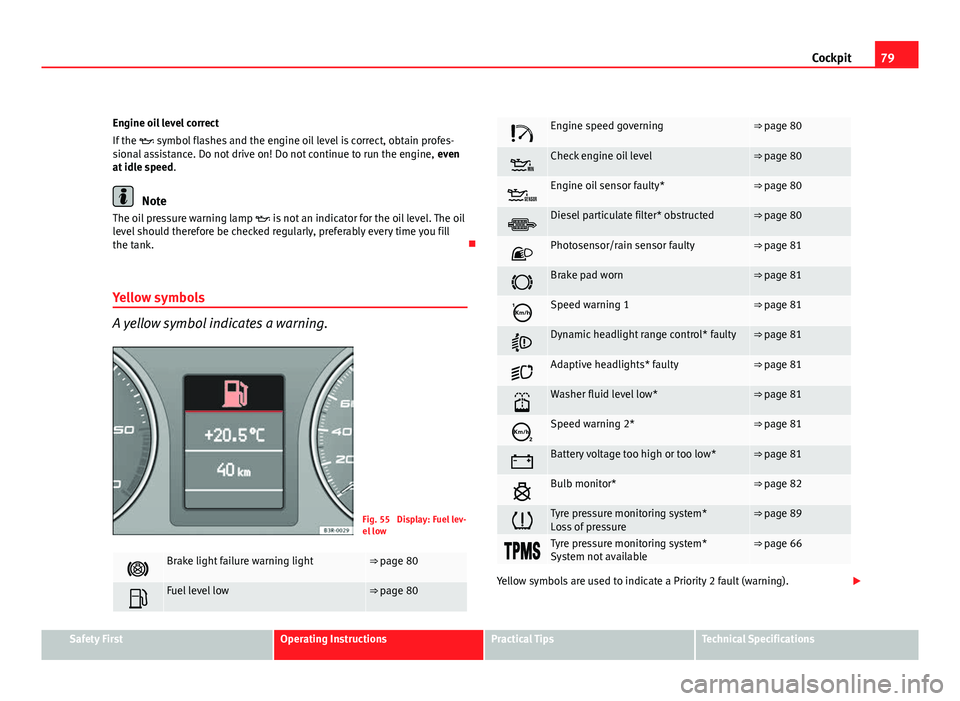
Yellow symbols
A yellow symbol indicates a warning.
Fig. 55 Display: Fuel lev-
el low
Brake light failure warning light⇒ page 80
Fuel level low⇒ page 80
Engine speed governing⇒ page 80
Check engine oil level⇒ page 80
Engine oil sensor faulty*⇒ page 80
Diesel particulate filter* obstructed⇒ page 80
Photosensor/rain sensor faulty⇒ page 81
Brake pad worn⇒ page 81
Speed warning 1⇒ page 81
Dynamic headlight range control* faulty⇒ page 81
Adaptive headlights* faulty⇒ page 81
Washer fluid level low*⇒ page 81
Speed warning 2*⇒ page 81
Battery voltage too high or too low*⇒ page 81
Bulb monitor*⇒ page 82
Tyre pressure monitoring system*
Loss of pressure⇒ page 89
Tyre pressure monitoring system*
System not available⇒ page 66
Yellow symbols are used to indicate a Priority 2 fault (warning).
Safety FirstOperating InstructionsPractical TipsTechnical Specifications
Page 82 of 319
80Cockpit
Yellow symbols are accompanied by one warning buzzer. The function indi-
cated should be checked as soon as possible. If several Priority 2 faults are
detected at the same time, the symbols are displayed one after the other for
about 2 seconds at a time.
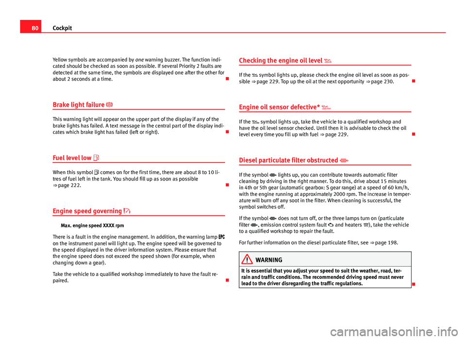
Brake light failure
This warning light will appear on the upper part of the display if any of the
brake lights has failed. A text message in the central part of the display indi-
cates which brake light has failed (left or right).
Fuel level low
When this symbol comes on for the first time, there are about 8 to 10 li-
tres of fuel left in the tank. You should fill up as soon as possible
⇒ page 222.
Engine speed governing
Max. engine speed XXXX rpm
There is a fault in the engine management. In addition, the warning lamp
on the instrument panel will light up. The engine speed will be governed to
the speed displayed in the driver information system. Please ensure that
the engine speed does not exceed the speed shown (for example, when
changing down a gear).
Take the vehicle to a qualified workshop immediately to have the fault re-
paired. Checking the engine oil level
If the symbol lights up, please check the engine oil level as soon as pos-
sible ⇒ page 229. Top up the oil at the next opportunity ⇒ page 230.
Engine oil sensor defective*
If the symbol lights up, take the vehicle to a qualified workshop and
have the oil level sensor checked. Until then it is advisable to check the oil
level every time you fill up with fuel ⇒ page 229.
Diesel particulate filter obstructed
If the symbol lights up, you can contribute towards automatic filter
cleaning by driving in the right manner. To do this, drive about 15 minutes
in 4th or 5th gear (automatic gearbox: S gear range) at a speed of 60 km/h,
with the engine running at approximately 2000 rpm. The increase in temper-
ature will burn off any soot in the filter. When cleaning is successful, the
symbol switches off.
If the symbol does not turn off, or the three lamps turn on (particulate
filter , emission control system fault and heaters ), take the vehicle
to a qualified workshop to repair the fault.
For further information on the diesel particulate filter, see ⇒ page 198.
WARNING
It is essential that you adjust your speed to suit the weather, road, ter-
rain and traffic conditions. The recommended driving speed must never
lead to the driver disregarding the traffic regulations.
Page 87 of 319
85
Cockpit
Onboard computer Introduction
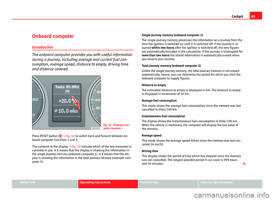
The onboard computer provides you with useful information
during a journey, including average and current fuel con-
sumption, average speed, distance to empty, driving time
and distance covered.
Fig. 59 Onboard com-
puter: memory 1
Press RESET button B
⇒ fig. 60 to switch back and forward between on-
board computer functions 1 and 2.
The numbers in the display ⇒ fig. 59 indicate which of the two memories is
currently in use. A 1 means that the display is showing the information in
the single journey memory (onboard computer 1). A 2 means that the dis-
play is showing the information in the total journey memory (onboard com-
puter 2). Single-journey memory (onboard computer 1)
The single-journey memory processes the information on a journey from the
time the ignition is switched on until it is switched off. If the journey is re-
sumed within two hours after the ignition is switched off, the new figures
are automatically included in the calculation. If the journey is interrupted for
more than two hours the stored information is automatically erased when
you resume your journey.
Total-journey memory (onboard computer 2)
Unlike the single-journey memory, the total-journey memory is not erased
automatically. Hence, you can determine the period for which you wish the
onboard computer to supply figures.
Distance to empty
The estimated distance to empty is displayed in km. The distance to empty
is displayed in increments of 10 km.
Average fuel consumption
This mode shows the average fuel consumption since the memory was last
cancelled in litres/100 km.
Instantaneous fuel consumption
The display shows the instantaneous fuel consumption in litres/100 km.
When the vehicle is stationary, the computer will display the last value in
the memory.
Average speed
This mode shows the average speed driven since the memory was last can-
celled (in km/h).
Driving time
This display shows the period of time which has elapsed since the memory
was last cancelled. The longest possible period it can cover is 999 hours
and 59 minutes.
Safety FirstOperating InstructionsPractical TipsTechnical Specifications
Page 88 of 319
86Cockpit
Driving time warning
After 2 hours of continuous driving, the display automatically switches over
to the driving time display of 2:00. At the same time the driving time display
starts flashing. This is to remind the driver to take a break.
The driving time warning can be switched off by briefly pressing the func-
tion selector switch or the Reset
button ⇒ fig. 60.
If you continue driving or take a break for less than 10 minutes, the driving
time warning will switch on once again when the total driving time is 4:00
hours, 6:00 hours, etc. However, if you take a break for more than 10 mi- nutes, the driving time warning clock will be erased.
Distance covered
This display shows the distance you have covered since the memory was
last cancelled. The longest possible distance which can be recorded is
9999.9 km.
Note
● The displays for fuel consumption (average and instantaneous), dis-
tance to empty and speed are shown in metric units.
● The information in the memory is lost if the battery is disconnected. Operation
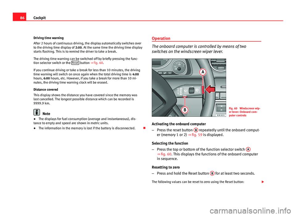
The onboard computer is controlled by means of two
switches on the windscreen wiper lever.
Fig. 60 Windscreen wip-
er lever: Onboard com-
puter controls
Activating the onboard computer
– Press the reset button B
repeatedly until the onboard comput-
er (memory 1 or 2) ⇒ fig. 59 is displayed.
Selecting the function
– Press the top or bottom of the function selector switch A
⇒ fig. 60. This displays the functions of the onboard computer
in sequence.
Resetting to zero
– Press and hold the Reset button B
for at least two seconds.
The following values can be reset to zero using the Reset button:
Page 89 of 319
87
Cockpit
● Journey duration
● Distance covered
● Average fuel consumption
● Average speed
The onboard computer can only be operated when the ignition is switched
on. When the ignition is switched on, the display shows the function that
was last selected.
As well as the figures from the onboard computer (1 or 2), the display can
also show information from the navigation system*. Press the Reset button B
briefly to switch back and forward between these displays.
Note
● If you keep the Reset button pressed for longer than two seconds, it will
reset the currently displayed figure to zero (for instance average fuel con-
sumption).
● Faults detected by the auto-check control will be displayed even if the
display is off.
● The information in the memory is lost if the battery is disconnected.
Safety FirstOperating InstructionsPractical TipsTechnical Specifications