technical specifications Seat Exeo ST 2012 Owner's manual
[x] Cancel search | Manufacturer: SEAT, Model Year: 2012, Model line: Exeo ST, Model: Seat Exeo ST 2012Pages: 325, PDF Size: 5.56 MB
Page 279 of 325

277
If and when
Changing the dipped beam headlight bulb
The procedure for changing the bulb is the same on both
sides.
Fig. 210 Dipped beam
headlights
Fig. 211 Dipped beam
headlights
– Switch off the ignition and the lights. –
Raise the bonnet.
– Move the brace ⇒ Fig. 210 1
in the direction of the arrow and
remove the rigid cover, separating the brace side and then re-
moving the two tabs from the other end of the cover.
– Pull the connector ⇒ Fig. 211 2
from the bulb.
– Unclip the retainer spring ⇒ Fig. 211 3
pressing inwards to the
right.
– Remove the bulb and fit the new one in the headlight casing
with the tab upwards, starting to position it from below.
– Clip on the spring, raising it and pressing it slightly while turn-
ing it anticlockwise. To ensure correct lighting, the filament
must be vertical. When changing the bulb, you can check the
position of the bulb through the headlight glass.
– Connect the connector to the bulb.
– Fit the cover, first inserting the side tabs and then closing the
cover and the brace. Make sure that the gasket sits well on the
casing cover during the operation.
– Check whether the new bulb is working.
– Have the headlight settings checked as soon as possible.
Safety FirstOperating InstructionsPractical TipsTechnical Specifications
Page 281 of 325
279
If and when
Changing the side light bulb (inside of vehicle)
The procedure for changing the bulb is the same on both
sides.
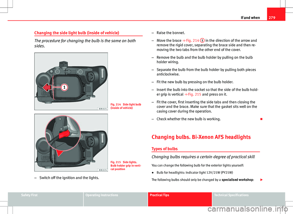
Fig. 214 Side light bulb
(inside of vehicle)
Fig. 215 Side lights.
Bulb holder grip in verti-
cal position
– Switch off the ignition and the lights. –
Raise the bonnet.
– Move the brace ⇒ Fig. 214 1
in the direction of the arrow and
remove the rigid cover, separating the brace side and then re-
moving the two tabs from the other end of the cover.
– Remove the bulb and the bulb holder by pulling on the bulb
holder wiring.
– Separate the bulb from the bulb holder by pulling both pieces
anticlockwise.
– Fit the new bulb by pressing on the bulb holder.
– Insert the bulb into the socket so that the side of the bulb hold-
er grip is vertical ⇒ Fig. 215 and press on it.
– Fit the cover, first inserting the side tabs and then closing the
cover and the brace. Make sure that the gasket sits well on the
casing cover during the operation.
– Check whether the new bulb is working.
Changing bulbs. Bi-Xenon AFS headlights Types of bulbs
Changing bulbs requires a certain degree of practical skill
You can change the following bulb for the exterior lights yourself:
● Bulb for headlights: Indicator light 12V/21W (PY21W)
The following bulbs should only be changed by a specialised workshop:
Safety FirstOperating InstructionsPractical TipsTechnical Specifications
Page 283 of 325
281
If and when
Fitting the air duct
Once the bulb(s) for the right-side headlight have been
changed, the air duct must be re-installed.
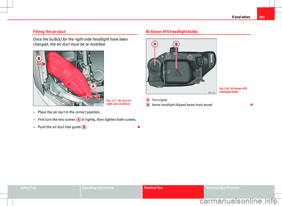
Fig. 217 Air duct on
right side of vehicle
– Place the air duct in the correct position.
– First turn the two screws A
in lightly, then tighten both screws.
– Push the air duct into guide B
. Bi-Xenon AFS headlight bulbs
Fig. 218 Bi-Xenon AFS
headlight bulbs
Turn signal
Xenon headlight (dipped beam/main beam)
A
B
Safety FirstOperating InstructionsPractical TipsTechnical Specifications
Page 285 of 325
283
If and when
Changing tail light bulbs (on side panel)
Overview of tail lights
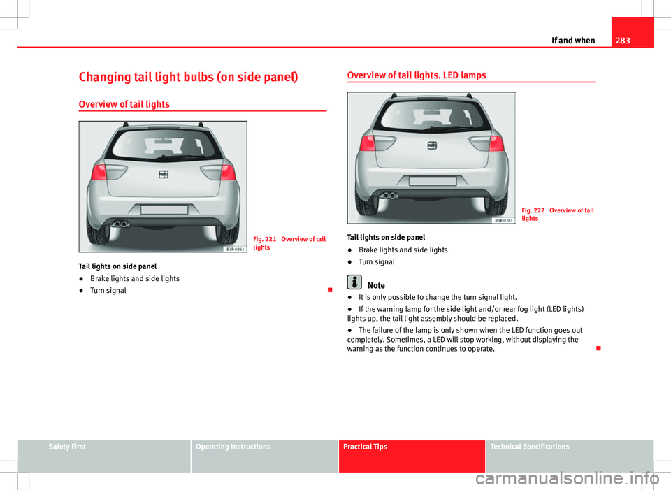
Fig. 221 Overview of tail
lights
Tail lights on side panel
● Brake lights and side lights
● Turn signal Overview of tail lights. LED lamps
Fig. 222 Overview of tail
lights
Tail lights on side panel
● Brake lights and side lights
● Turn signal
Note
● It is only possible to change the turn signal light.
● If the warning lamp for the side light and/or rear fog light (LED lights)
lights up, the tail light assembly should be replaced.
● The failure of the lamp is only shown when the LED function goes out
completely. Sometimes, a LED will stop working, without displaying the
warning as the function continues to operate.
Safety FirstOperating InstructionsPractical TipsTechnical Specifications
Page 287 of 325
285
If and when
Remove the bulb holder
When changing a bulb, you must first remove the bulb hold-
er.
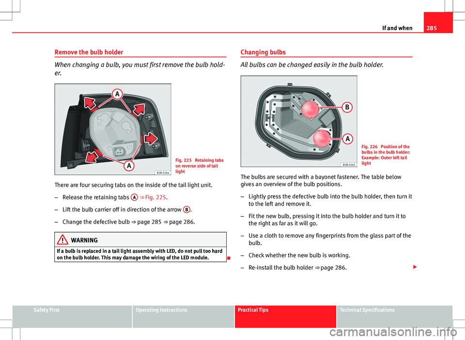
Fig. 225 Retaining tabs
on reverse side of tail
light
There are four securing tabs on the inside of the tail light unit.
– Release the retaining tabs A
⇒ Fig. 225.
– Lift the bulb carrier off in direction of the arrow B
.
– Change the defective bulb ⇒ page 285 ⇒ page 286.
WARNING
If a bulb is replaced in a tail light assembly with LED, do not pull too hard
on the bulb holder. This may damage the wiring of the LED module.
Changing bulbs
All bulbs can be changed easily in the bulb holder.
Fig. 226 Position of the
bulbs in the bulb holder:
Example: Outer left tail
light
The bulbs are secured with a bayonet fastener. The table below
gives an overview of the bulb positions.
– Lightly press the defective bulb into the bulb holder, then turn it
to the left and remove it.
– Fit the new bulb, pressing it into the bulb holder and turn it to
the right as far as it will go.
– Use a cloth to remove any fingerprints from the glass part of the
bulb.
– Check whether the new bulb is working.
– Re-install the bulb holder ⇒ page 286.
Safety FirstOperating InstructionsPractical TipsTechnical Specifications
Page 289 of 325
287
If and when
– Position the bulb holder on the tail light and align it so that it is
securely seated.
– Press the bulb holder into the tail light until it engages.
– Check that all four retaining tabs ⇒ Fig. 228 -arrows- have en-
gaged.
– Re-install the tail light unit ⇒ page 287.
Fitting the tail light unit
The tail light unit is easy to fit.
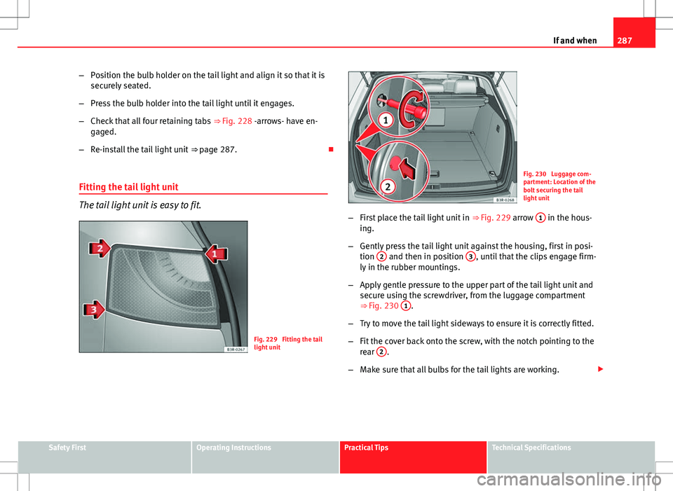
Fig. 229 Fitting the tail
light unit
Fig. 230 Luggage com-
partment: Location of the
bolt securing the tail
light unit
– First place the tail light unit in ⇒ Fig. 229 arrow 1
in the hous-
ing.
– Gently press the tail light unit against the housing, first in posi-
tion 2
and then in position 3, until that the clips engage firm-
ly in the rubber mountings.
– Apply gentle pressure to the upper part of the tail light unit and
secure using the screwdriver, from the luggage compartment
⇒ Fig. 230 1
.
– Try to move the tail light sideways to ensure it is correctly fitted.
– Fit the cover back onto the screw, with the notch pointing to the
rear 2
.
– Make sure that all bulbs for the tail lights are working.
Safety FirstOperating InstructionsPractical TipsTechnical Specifications
Page 291 of 325
289
If and when
Remove the bulb holder
The rear lid must be open to change the bulbs.
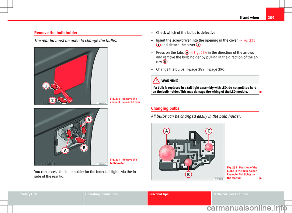
Fig. 233 Remove the
cover of the rear lid trim
Fig. 234 Remove the
bulb holder
You can access the bulb holder for the inner tail lights via the in-
side of the rear lid. –
Check which of the bulbs is defective.
– Insert the screwdriver into the opening in the cover ⇒ Fig. 233
1
and detach the cover 2.
– Press on the tabs A
⇒ Fig. 234 in the direction of the arrows
and remove the bulb holder by pulling in the direction of the ar-
row B
.
– Change the bulbs ⇒ page 289 ⇒ page 290.
WARNING
If a bulb is replaced in a tail light assembly with LED, do not pull too hard
on the bulb holder. This may damage the wiring of the LED module.
Changing bulbs
All bulbs can be changed easily in the bulb holder.
Fig. 235 Position of the
bulbs in the bulb holder.
Example: Tail lights on
the rear lid
Safety FirstOperating InstructionsPractical TipsTechnical Specifications
Page 293 of 325
291
If and when
Position of the bulbs
Pos.
⇒ Fig. 235Bulb function
AReverse lightsP21W LLBRear fog lightH21W
Fitting the bulb holder
The bulb holder is easy to fit. – Position the bulb holder on the tail light and align it so that it is
securely seated.
– Press the bulb holder into the tail light until it engages.
– Fit the cover back in the interior trim so that it engages.
– Make sure that all bulbs for the tail lights are working. Side turn signals
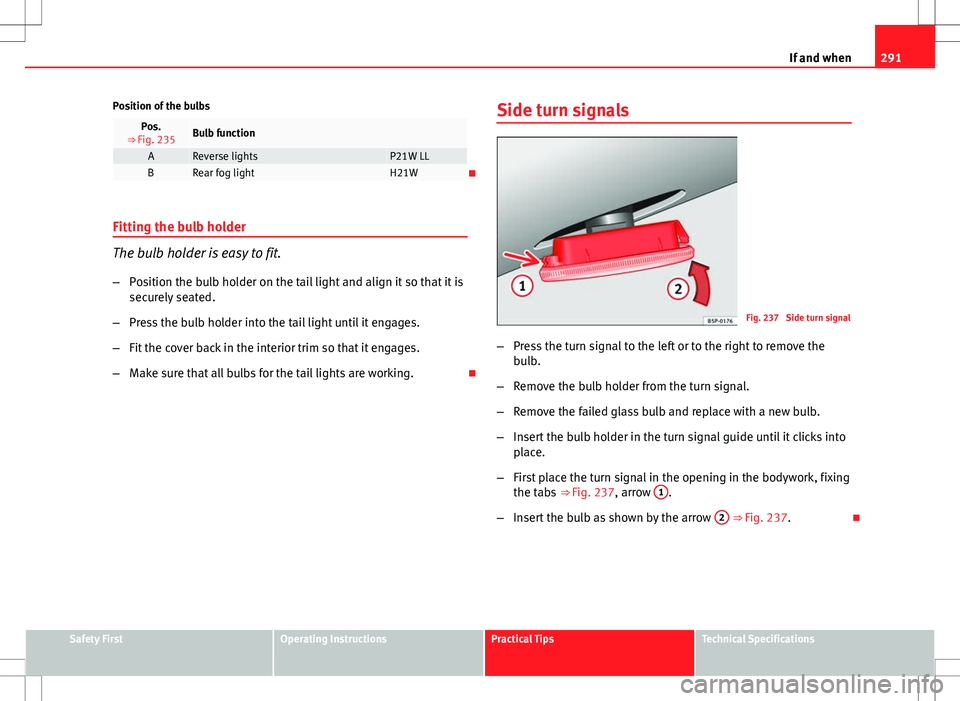
Fig. 237 Side turn signal
– Press the turn signal to the left or to the right to remove the
bulb.
– Remove the bulb holder from the turn signal.
– Remove the failed glass bulb and replace with a new bulb.
– Insert the bulb holder in the turn signal guide until it clicks into
place.
– First place the turn signal in the opening in the bodywork, fixing
the tabs ⇒ Fig. 237, arrow 1
.
– Insert the bulb as shown by the arrow 2
⇒ Fig. 237.
Safety FirstOperating InstructionsPractical TipsTechnical Specifications
Page 295 of 325

293
If and when
– To remove the light cover, unscrew the bolts ⇒ Fig. 240.
– Remove the bulb, moving it in the direction of the arrow and
outwards ⇒ Fig. 241.
– Installation is done in the reverse order.
Sun visor light
Fig. 242 Removing sun
visor light
Fig. 243 Removing sun
visor light
– Remove the bulb carefully, using the flat part of a screwdriver
⇒ Fig. 242.
– Use a screwdriver to remove the protective cover.
– Remove the bulb, moving it in the direction of the arrow and
outwards ⇒ Fig. 243.
Jump-starting
Jump leads
The jump lead must have a sufficient wire cross section. If the engine fails to start because of a discharged battery, the battery can
be connected to the battery of another vehicle to start the engine.
Safety FirstOperating InstructionsPractical TipsTechnical Specifications
Page 297 of 325

295
If and when
– Connect one end of the red jump lead to the positive +
termi-
nal of the vehicle with the flat battery A ⇒ Fig. 245.
– Connect the other end of the red jump lead to the positive ter-
minal +
in the vehicle providing assistance B.
– Connect one end of the black jump lead X
to a suitable ground
terminal, a solid piece of metal in the engine block, or to the en-
gine block ⇒ Fig. 245.
– Connect the other end of the black jump lead X
to a solid met-
al component bolted to the engine block or to the engine block
itself of the vehicle with the flat battery. However, connect it to
a point as far as possible from the battery A
.
4. Position the leads in such a way that they cannot come into contact with any moving parts in the engine compartment.
Starting
5. Start the engine of the vehicle with the boosting battery and let it run at idling speed.
6. Start the engine of the vehicle with the flat battery and wait one or two minutes until the engine is running.
Removing the jump leads
7. Before you remove the jump leads, switch off the headlights (if they are switched on).
8. Turn on the heater blower and heated rear window in the vehi- cle with the flat battery. This helps minimise voltage peaks
which are generated when the leads are disconnected.
9. When the engine is running, disconnect the leads in reverse or- der to the details given above. Connect the battery clamps so they have good metal-to-metal contact with
the battery terminals.
If the engine fails to start, switch off the starter after about 10 seconds and
try again after about half a minute.
WARNING
● Please note the safety warnings referring to working in the engine
compartment ⇒ page 234.
● The battery providing assistance must have the same voltage as the
flat battery (12V) and approximately the same capacity (see imprint on
battery). Failure to comply could result in an explosion.
● Never use jump leads when one of the batteries is frozen. Danger of
explosion! Even after the battery has thawed, battery acid could leak and
cause chemical burns. If a battery freezes, it should be replaced.
● Keep sparks, flames and lighted cigarettes away from batteries, dan-
ger of explosion. Failure to comply could result in an explosion.
● Observe the instructions provided by the manufacturer of the jump
leads.
● Do not connect the negative cable from the other vehicle directly to
the negative terminal of the flat battery. The gas emitted from the battery
could be ignited by sparks. Danger of explosion.
● Do not attach the negative cable from the other vehicle to parts of the
fuel system or to the brake line.
● The non-insulated parts of the battery clamps must not be allowed to
touch. The jump lead attached to the positive battery terminal must not
touch metal parts of the vehicle, this can cause a short circuit.
● Position the leads in such a way that they cannot come into contact
with any moving parts in the engine compartment.
● Do not bend over the batteries. This could result in chemical burns.
Safety FirstOperating InstructionsPractical TipsTechnical Specifications