change time Seat Ibiza 2017 Edition 11.17 Owner's Guide
[x] Cancel search | Manufacturer: SEAT, Model Year: 2017, Model line: Ibiza, Model: Seat Ibiza 2017Pages: 312, PDF Size: 6.51 MB
Page 222 of 312
Operation
programmed speed and ACC status will be
di s
p
layed ››› Fig. 196.
What ACC settings are possible?
● Setting your speed ›››
page 220.
● Setting your distance ›››
page 220.
● Connecting and activating the ACC
›››
page 220.
● Disconnecting and deactivating the ACC
›››
page 220.
● Adjusting the default distance level at the
star
t of your journey ››› page 220.
● Adjusting the driving profile ›››
page 221.
● Conditions in which the ACC does not react
›››
page 221.
Setting speed
To set your speed, move the third lever loca-
ted in position 1 upwards or downwards un-
ti l
the de
sired speed is shown on the instru-
ment panel display. The speed adjustment is
made at 10 km/h (6 mph) intervals.
Once you are driving , if you wish to set the
current speed as the vehicle’s cruise speed
and activate the ACC, press the button
››› Fig. 199. If you wish to increase or reduce
speed by intervals of 1 km/h (0.6 mph),
move the lever to position 2
›
››
Fig. 198 or
press the button, respectively.
The set speed can be changed when the ve-
hicle is stopped or during driving, as you like. Any modification to the programmed speed
wil
l be shown on the bottom left part of the
instrument panel display ››› Fig. 196.
Setting your distance level
To increase/reduce the distance level, press
the rocker switch towards the left/right
››› Fig. 199 A .
The in s
trument
panel display shows the mod-
ification of the distance level. There are 5 dis-
tance levels to choose from. SEAT recom-
mends level 3. The set distance can be
changed when the vehicle is stopped or dur-
ing driving, as you like ››› .
C onnectin
g and activ
ating the ACC
To connect and activate the ACC, the position
of the gearbox selector lever, the vehicle
speed and the position of the third level of
the ACC must all be taken into account.
● With a manual gearbox, the gearbox selec-
tor lev
er must be in any gear except first, and
speed must be greater than approximately 30
km/h. With an automatic gearbox, the gear-
box selector lever must be in position D or S.
● To activate the ACC, with the third lever in
position 1 press the
butt
on or mo
ve the
third lever of the ACC to position 2 ›››
Fig. 198. At thi s
point, the image of the
ACC on the instrument panel display will
switch to Active mode ››› Fig. 196. When the ACC function is active, the vehicle
trav
el
s at a set speed and distance from the
vehicle ahead. Both speed and distance can
be changed at any time.
Disconnecting and deactivating the ACC
To disconnect the ACC move the lever to the 0 position
›››
Fig. 198
(en
gaged). An ACC
deactivated message appears and the
function is totally deactivated.
If you do not wish to disconnect the ACC, just
to switch it temporarily to inactive mode
(Standby), move the third lever to position 3 ›››
Fig. 198 or pre s
s the brake pedal.
It will also switch to inactive mode (Standby)
if the vehicle is stopped and the driver door
is opened.
Adjusting the default distance level at the
start of your journey.
In wet road conditions, you should always set
a larger distance with regard to the vehicle in
front than when driving in dry conditions.
The following distances can be preselected:
● Very short
● Short
● Media
● Long
● Very long
220
Page 227 of 312
Driver assistance systems
Factors that may affect how the radar sensor
oper at
e
s
If laser sensor operation is impaired, due to
heavy rain, spray, snow or mud, the ACC is
deactivated temporarily. The relevant text
message will appear in the dash panel dis-
play. If necessary, clean the radar sensor
››› Fig. 197.
When the radar sensor begins to operate
properly again, the ACC will automatically be
available again. The message on the instru-
ment panel screen will switch off and the ACC
will be reactivated again.
ACC operation may be affected by a strong ra-
dar reverse reflection, for example in a closed
car park.
Trailer mode
When driving with trailer the ACC controls
less dynamically.
Overheated brakes
If the brakes overheat, for example after
abrupt braking or in long and steep slopes,
the ACC may be deactivated temporarily. The
relevant text message will appear in the dash
panel display. In this case, adaptive cruise
control cannot be activated.
Adaptive cruise control can be reactivated
once brake temperature has cooled suffi-
ciently. The message will disappear from the
instrument panel display. If the message ACCnot available
remain s on for quite a long
time it means that there is a fault. Contact a
specialised workshop. SEAT recommends vis-
iting a SEAT dealership. WARNING
If you do not heed the Press the brake
mes s
age, the vehicle may initiate an involun-
tary movement and could crash into the vehi-
cle ahead. In any event, before driving off,
check that the road is clear. The radar sensor
may not detect obstacles on the road. This
could cause an accident and serious injuries.
If necessary, apply the brake. SEAT Drive Profile*
Intr oduction SEAT Drive Profile enables the driver to
c
hoo
se betw
een four profiles or modes, Nor-
mal , Sport , Eco and Individual , that
modify the behaviour of various vehicle func-
tions, providing different driving experiences.
The Individual profile can be configured
according to personal preferences. The other
profiles are fixed. Description Depending on the equipment fitted in the ve-
hicl
e,
SEAT Drive Profile can operate on the
following functions:
Engine
Depending on the profile selected, the en-
gine responds more spontaneously or more
in harmony with the movements of the accel-
erator. Additionally, when Eco mode is selec-
ted, the Start-stop function is automatically
activated.
In vehicles with automatic transmission, the
gear change points are modified to position
them in lower or higher engine speed ranges.
Additionally, the Eco mode activates the In-
ertia function, enabling consumption to be
further reduced.
In manual gearbox vehicles, Eco mode cau-
ses the gear change recommendation indica-
tions that appear on the instrument panel to
vary, facilitating more efficient driving.
“Dual Ride” suspension
The “Dual Ride” suspension features a com-
fortable suspension in the Eco and Normal
profiles, suitable for daily use. Contrasting
with this it features a sporty suspension in »
225
Technical data
Advice
Operation
Emergencies
Safety
Page 233 of 312
Driver assistance systems
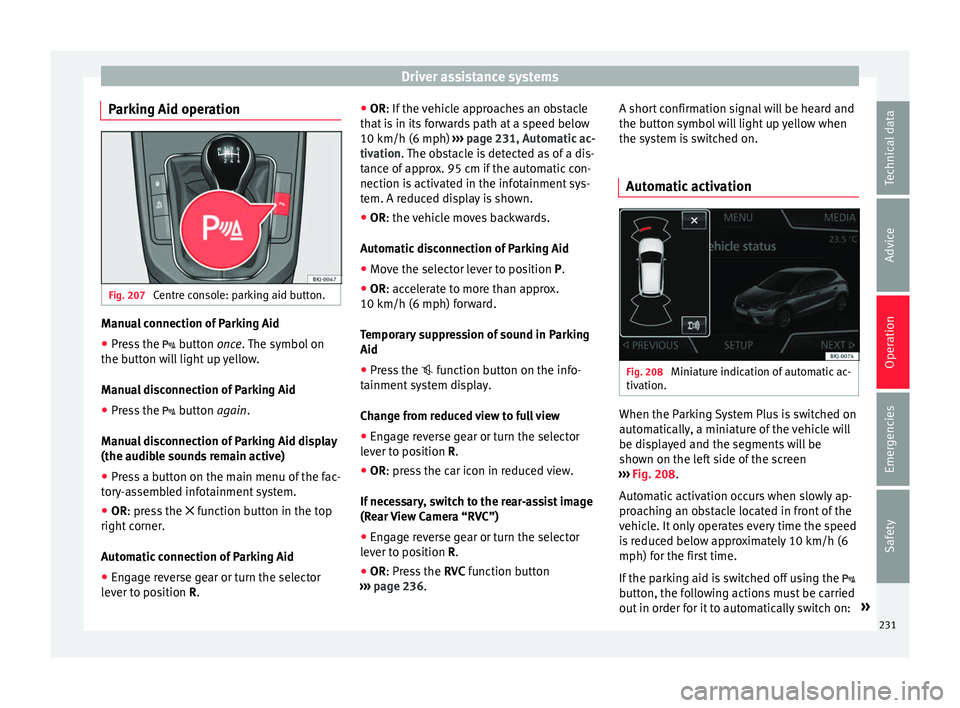
Parking Aid operation Fig. 207
Centre console: parking aid button. Manual connection of Parking Aid
● Press the butt
on once. The symbol on
the button will light up yellow.
Manual disconnection of Parking Aid
● Press the button
again.
Manual disconnection of Parking Aid display
(the audible sounds remain active)
● Press a button on the main menu of the fac-
tory
-assembled infotainment system.
● OR: press the fu
nction button in the top
right corner.
Automatic connection of Parking Aid
● Engage reverse gear or turn the selector
lever t
o position R. ●
OR: If the v
ehicle approaches an obstacle
that is in its forwards path at a speed below
10 km/h (6 mph) ››› page 231, Automatic ac-
tivation. The obstacle is detected as of a dis-
tance of approx. 95 cm if the automatic con-
nection is activated in the infotainment sys-
tem. A reduced display is shown.
● OR: the vehicle moves backwards.
Autom
atic disconnection of Parking Aid
● Move the selector lever to position P.
● OR: accelerate to more than approx.
10 km/h (6 mph) for
ward.
Temporary suppression of sound in Parking
Aid
● Press the function b
utton on the info-
tainment system display.
Change from reduced view to full view
● Engage reverse gear or turn the selector
lever t
o position R.
● OR: press the car icon in reduced view.
If nec
essary, switch to the rear-assist image
(Rear View Camera “RVC”)
● Engage reverse gear or turn the selector
lever t
o position R.
● OR: Press the RVC fu
nction button
››› page 236. A short confirmation signal will be heard and
the button symbo
l will light up yellow when
the system is switched on.
Automatic activation Fig. 208
Miniature indication of automatic ac-
tiv ation. When the Parking System Plus is switched on
aut
om
atic
ally, a miniature of the vehicle will
be displayed and the segments will be
shown on the left side of the screen
››› Fig. 208.
Automatic activation occurs when slowly ap-
proaching an obstacle located in front of the
vehicle. It only operates every time the speed
is reduced below approximately 10 km/h (6
mph) for the first time.
If the parking aid is switched off using the
button, the following actions must be carried
out in order for it to automatically switch on: »
231
Technical data
Advice
Operation
Emergencies
Safety
Page 235 of 312
Driver assistance systems
off – deactiv
at es the Automatic ac-
tivation option ››› page 231.
Front volume*
Volume in the front and rear area.
Front sound settings/sharpness*
Frequency (tone) of the sound in the front
area.
Rear volume*
Volume in the rear area.
Rear sound settings/sharpness*
Frequency (tone) of the sound in the rear
area.
Adjust volume
With the parking aid switched on, the active
audio/video source volume will be reduced
to the intensity of the selected setting.
Error messages When the Parking Aid is activated or when it
i
s
sw
itched on, if a message reporting a Park-
ing aid error is displayed on the instrument
panel, there is a fault in the system.
If the fault does not disappear before discon-
necting the ignition, the next time that the
parking aid is engaged in reverse, no audible signal of the existence of a fault will be is-
sued.
Park
ing System Plus*
If there is a fault in the parking aid system a
message will appear on the instrument panel
indicating the error. In addition the key
LED will blink.
If there is a fault in a sensor, the symbol is
displayed on the Easy Connect display in
front of/behind the vehicle. If a rear sensor is
faulty, only the obstacles in area A are dis-
p l
a
yed ››› Fig. 206. If a front sensor is faulty,
only the obstacles in area B are displayed.
Hav e the f
au
lt corrected by a specialised
workshop without delay.
Towing bracket In vehicles equipped with a towing bracket
dev
ic
e fr
om the factory, when the trailer is
connected electrically, the Parking Aid rear
sensors will not be activated when reverse
gear is engaged, when the selector lever is
turned to position R or when the button is
pressed.
Parking System Plus
The distance to possible obstacles at the rear
of the vehicle will not be displayed on the screen and nor will it be indicated by means
of audibl
e sound signals.
The Easy Connect system screen will only dis-
play objects detected at the front, and the ve-
hicle's trajectory will be hidden.
Braking while manoeuvring function* 3 Only valid with Parking System Plus
The emer
g
ency braking function is used to
minimise damage in the event of a collision.
Depending on the equipment, if the Parking
Aid is active, the braking while manoeuvring
function activates emergency braking when it
detects an obstacle in the vehicle’s path that
could cause a collision, driving forwards or in
reverse.
The function will not brake if the Parking Aid
is activated automatically. For the system to
operate, manoeuvring speed must be be-
tween 2.5 and 10 km/h (between 1.5 and 6
mph) for the front area and between 1.5 and
10 km/h (between 1 and 6 mph) for the rear.
Following an intervention, the braking while
manoeuvring function will be inactive in the
same direction of travel for 5 metres. Once
the gear is changed, or the selector lever’s
position is changed, the function will be ac-
tive again. The Parking Aid’s limitations ap-
ply. »
233
Technical data
Advice
Operation
Emergencies
Safety
Page 265 of 312
Checking and refilling levels
●
Do not tr y
to add any more additive after
the nozzle has stopped for the first time. The
AdBlue tank could overflow and AdBlue could
spill out.
● Only use AdBlue ®
that c
omplies with ISO
22241-1. Only use original containers.
● Never mix AdBlue ®
with wat
er, fuel or addi-
tives. Any type of damage caused by such a
mixture will not be covered by the warranty.
● Never pour AdBlue ®
into the fuel
tank. This
could result in engine damage.
● Do not carry the refill bottle inside the vehi-
cle. If
there is a leak (due to temperature
changes or damage to the bottle), the
AdBlue ®
may damage the vehicle. For the sake of the environment
Dispose of the refill bottle in an environment-
friendly m anner
.Note
You can buy refill bottles that are adequate
for AdBlue ®
u se at
SEAT dealerships. Working in the engine compart-
ment
Saf ety
not
es for work in the engine
compartment Read the additional information carefully
›› ›
page 17
Before starting any work on the engine or in
the engine compartment:
1. Switch off the engine and remove the key from the ignition.
2. Ap
ply the handbrake.
3. Move the gear lever to neutral or the selec- tor lev
er to position P.
4. Wait for the engine to cool down.
5. Keep children away from the vehicle.
6. Raise the bonnet ›››
page 264.
You should not do any work in the engine
compartment unless you know exactly how to
carry out the jobs and have the correct tools!
Have the work carried out by a specialised
workshop if you are uncertain.
All service fluids and consumables, e.g. cool-
ant, engine oil, spark plugs and batteries,
are under constant development. SEAT pro-
vides a constant flow of information to Tech-
nical Services concerning modifications. For
this reason, we recommend you have service fluids and consumables replaced by a Techni-
cal
Service. Please observe the relevant in-
structions ››› page 247. The engine compart-
ment of the vehicle is a hazardous area ››› .
WARNING
All work on the engine or in the engine com-
par tment, e.
g. checking and refilling fluids,
involves the danger of injury and burns, acci-
dents and even fire.
● Never open the bonnet if you see steam,
smoke or coo
lant escaping from the engine
compartment. Otherwise, there is a risk of
sustaining burns. Wait until no more steam or
coolant is emitted, then allow the engine to
cool before carefully opening the bonnet.
● Switch off the engine and remove the key
from the ignition.
● App
ly the handbrake and move the gear
lever t
o neutral or selector lever to position P.
● Keep children away from the vehicle.
● Never touch hot engine parts. There is a
risk of
burns.
● Never spill liquids on a hot engine or on a
hot exh
aust gas system. This is a fire hazard.
● Avoid causing short-circuits in the electri-
cal
system, particularly at the points where
the jump leads are attached ›››
page 72.
The battery could explode.
● Never touch the radiator fan. It is tempera-
ture c
ontrolled and could start automatically,
even when the engine has been switched off
and the key removed from the ignition! » 263
Technical data
Advice
Operation
Emergencies
Safety
Page 269 of 312
Checking and refilling levels
diesel engines together, it means that the oil
c an be u
sed f
or both types of engines.
We recommend that the oil change indicated
in the Maintenance Programme, be per-
formed by a technical service or specialised
workshop.
The correct oil specifications for your engine
are listed in the ›››
page 59.
Service intervals
Service intervals can be flexible (LongLife
service) or fixed (dependent on time/dis-
tance travelled).
If the PR code that appears on the back of the
Maintenance Programme booklet is PR QI6,
this means that your vehicle has the LongLife
service program. If it lists the codes QI1, QI2,
QI3, QI4 or QI7, the interval service is de-
pendent on the time/distance travelled.
Flexible service intervals (LongLife service
intervals*)
Special oils and processes have been devel-
oped which, depending on the characteris-
tics and individual driving profiles, enable
the extension of the oil change service (Long-
Life service intervals).
Because this oil is essential for extending the
service intervals, it must only be used ob-
serving the following indications: ●
Avoid mi xing it with oil for fixed service in-
tervals.
● Only in exceptional circumstances, if the
engine oil
level is too low ››› page 268 and
LongLife oil is not available, it is permitted to
top up (once) with oil for fixed service inter-
vals ›››
page 59 (up to a maximum of 0.5
litres).
Fixed service intervals*
If your vehicle does not have the “LongLife
service interval” or it has been disabled (by
request), you may use oils for fixed service
intervals, which also appear in
››› page 59. In this case, your vehicle
must be serviced after a fixed interval of 1
year/15,000 km (10,000 miles)(whatever
comes first) ››› Booklet Maintenance Pro-
gramme.
● In exceptional circumstances, if the engine
oil l
evel is too low ››› page 268 and you can-
not obtain the oil specified for your vehicle,
you can add a small quantity of oil conform-
ing to the specification ACEA A2 or ACEA A3
(petrol engines) or ACEA B3 or ACEA B4 (die-
sel engines) (up to 0.5 l).
Vehicles with diesel particulate filter*
The Maintenance Programme states whether
your vehicle is fitted with a diesel particulate
filter. Only VW 507 00 engine oil, with reduced ash
formation, m
ay be used in diesel engines
equipped with particulate filter. Using other
types of oil will cause a higher soot concen-
tration and reduce the life of the DPF. There-
fore:
● Avoid mixing this oil with other engine oils.
● Only in exceptional circumstances, if the
engine oil
level is too low ››› page 268,
Checking engine oil level and you cannot ob-
tain the oil specified for your vehicle, you can
use a small quantity of oil (once) conforming
to the VW 506 00, VW 506 01, VW 505 00,
VW 505 01 or ACEA B3/ACEA B4 specification
(up to 0.5 l). Note
Before a long trip, we recommend finding an
engine oi l
that conforms to the correspond-
ing VW specifications and recommend keep-
ing it in the vehicle. This way, the correct en-
gine oil will always be available for a top-up if
needed. Warning lamp
If this warning lamp
is
r
ed it indicates
that the engine oil pressure is too low.
If this warning symbol starts to flash, and is
accompanied by three audible warnings,
switch off the engine and check the oil level.
If necessary, add more oil ›››
page 268. »
267
Technical data
Advice
Operation
Emergencies
Safety
Page 273 of 312
Checking and refilling levels
CAUTION
The original additives should never be mixed
with c oo
lants which are not approved by
SEAT. Otherwise, you run the risk of causing
severe damage to the engine and the engine
cooling system.
● If the fluid in the expansion tank is not pur-
ple b
ut is, for example, brown, this indicates
that the G13 additive has been mixed with an
inadequate coolant. The coolant must be
changed as soon as possible if this is the
case! This could result in serious faults and
engine damage. For the sake of the environment
Coolants and additives can contaminate the
env ir
onment. If any fluids are spilled, they
should be collected and correctly disposed
of, with respect to the environment. Brake fluid
Chec k
in
g the brake fluid levelRead the additional information carefully
› ›
›
page 60
The position of the brake fluid reservoir is
shown in the corresponding engine compart-
ment image ›››
page 266. The brake fluid res-
ervoir has a black and yellow cap. The brake fluid level drops slightly when the
vehicl
e is being used as the brake pads are
automatically adjusted as they wear.
However, if the level goes down noticeably in
a short time, or drops below the “MIN” mark,
there may be a leak in the brake system. A
display on the instrument panel will warn you
if the brake fluid level is too low ››› page 122. WARNING
Before opening the bonnet to check the brake
fluid lev el, r
ead and observe the warnings
››› page 263. Changing the brake fluid
The Maintenance Programme indicates brake
fluid c
h
an
ge intervals.
We recommend that you have the brake fluid
changed by a Technical Service.
Before opening the bonnet, please read and
follow the warnings ››› in Safety notes for
w ork
in the en
gine compartment on
page 263 in section “Safety notes for work-
ing in the engine compartment”.
In the course of time, brake fluid becomes
hygroscopic and absorbs water from the am-
bient air. If the water content in the brake flu-
id is too high, the brake system could cor-
rode. This also considerably reduces the boil-
ing point of the brake fluid. Heavy use of the brakes may then cause a vapour lock which
coul
d impair the braking effect.
Be sure to always use the correct brake fluid.
Only use brake fluid that expressly meets the
VW 501 14 standard.
You can buy VW 501 14 standard brake fluid
in a SEAT dealership or a SEAT Official Serv-
ice. If none is available, use only high-quality
brake fluid that meets DIN ISO 4925 CLASS 4
standards, or USA Standards FMVSS 116 DOT
4.
Using any other kind of brake fluid or one
that is not of a high quality may affect opera-
tion of the brake system and reduce its effec-
tiveness. Never use a brake fluid if the con-
tainer does not state that it complies with VW
501 14, DIN ISO 4925 CLASS 4 standards, or
USA standards FMVSS 116 DOT 4. WARNING
Brake fluid is poisonous. Old brake fluid im-
pair s
the braking effect.
● Before opening the bonnet to check the
brake fluid l
evel, read and observe the warn-
ings ››› page 263.
● Brake fluid should be stored in the closed
original
container in a safe place out of reach
of children. There is a toxic risk.
● Perform the brake fluid change according to
the Mainten
ance Programme. Heavy use of
the brakes may cause a vapour lock if the
brake fluid is left in the brake system for too » 271
Technical data
Advice
Operation
Emergencies
Safety
Page 275 of 312
Checking and refilling levels
seek medical care immediately. Neutralise
any
ac
id splashes on the skin or clothing
with a soapy solution, and rinse off with plen-
ty of water. If acid is swallowed by mistake,
consult a doctor immediately.
● Fires, sparks, open flames and smoking are
prohibit
ed. When handling cables and electri-
cal equipment, avoid causing sparks and
electrostatic charge. Never short the battery
terminals. High-energy sparks can cause in-
jury.
● A highly explosive mixture of gases is re-
lea
sed when the battery is under charge. The
batteries should be charged in a well-ventila-
ted room only.
● Keep children away from acid and batteries.
● Before working on the electrical system,
you mus
t switch off the engine, the ignition
and all electrical devices. The negative cable
on the battery must be disconnected. When a
light bulb is changed, you need only switch
off the light.
● Deactivate the anti-theft alarm by unlock-
ing the v
ehicle before you disconnect the bat-
tery! The alarm will otherwise be triggered.
● When disconnecting the battery from the
vehicl
e on-board network, disconnect first
the negative cable and then the positive ca-
ble.
● Switch off all electrical devices before re-
connecting the b
attery. Reconnect first the
positive cable and then the negative cable.
Never reverse the polarity of the connections.
This could cause an electrical fire. ●
Never c h
arge a frozen battery, or one which
has thawed. This could result in explosions
and chemical burns. Always replace a battery
which has frozen. A flat battery can also
freeze at temperatures close to 0°C (+32°F).
● Ensure that the vent hose is always connec-
ted to the b
attery.
● Never use a defective battery. This could
cause an e
xplosion. Replace a damaged bat-
tery immediately. CAUTION
● Nev er di s
connect the battery if the ignition
is switched on or if the engine is running.
This could damage the electrical system or
electronic components.
● Do not expose the battery to direct sunlight
over a lon
g period of time, as the intense ul-
traviolet radiation can damage the battery
housing.
● If the vehicle is left standing in cold condi-
tions f
or a long period, protect the battery
from “freezing”. If it freezes it will be dam-
aged. Warning lamp
It lights up
Alternator fault. The control lamp
lights up when the igni-
tion i s
switched on. It should go out when the
engine has started running.
If the control lamp lights up while driving,
the alternator is no longer charging the bat-
tery. You should immediately drive to the
nearest specialised workshop.
You should avoid using electrical equipment
that is not absolutely necessary because this
will drain the battery.
Checking the battery electrolyte level The electrolyte level should be checked regu-
l
arly
in high-mi
leage vehicles, in hot coun-
tries and in older batteries.
– Open the bonnet and open the battery cov-
er at the front
››› in Safety notes for work
in the en gine c
omp
artment on page 263
››› in Symbols and warnings on handling
the b att
er
y on page 272. For vehicles with
the battery under the spare wheel, open
the rear lid and lift the floor covering. The
battery is located next to the spare wheel.
– Check the colour display in the "magic eye"
on the top of the b
attery.
– If there are air bubbles in the window, tap
the window g
ently until they disperse. »
273
Technical data
Advice
Operation
Emergencies
Safety
Page 278 of 312
Advice
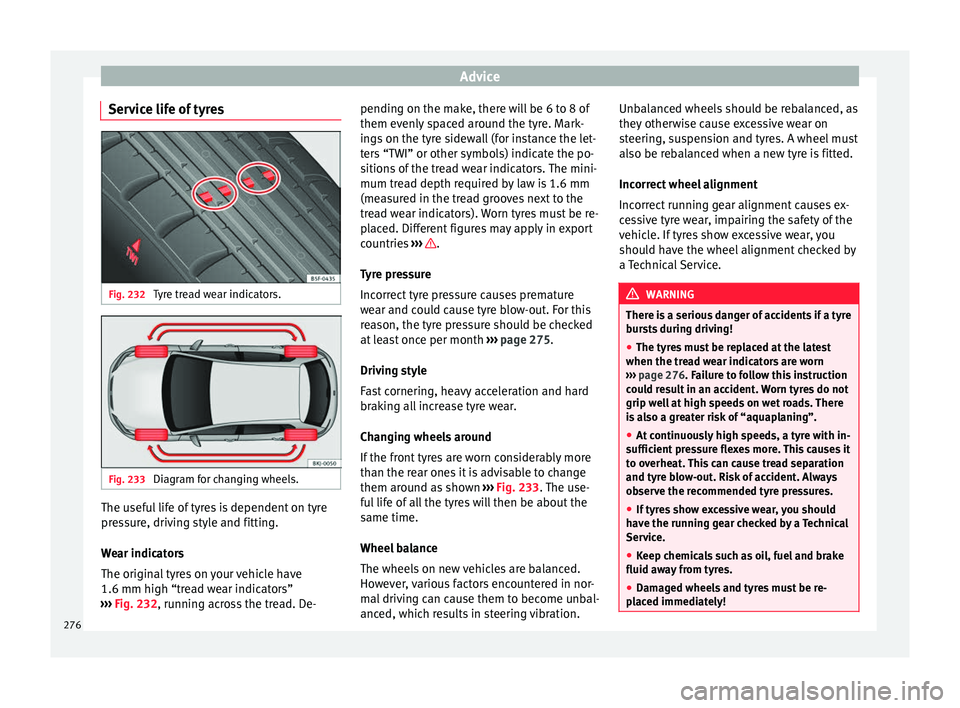
Service life of tyres Fig. 232
Tyre tread wear indicators. Fig. 233
Diagram for changing wheels. The useful life of tyres is dependent on tyre
pr
e
s
sure, driving style and fitting.
Wear indicators
The original tyres on your vehicle have
1.6 mm high “tread wear indicators”
››› Fig. 232, running across the tread. De- pending on the make, there will be 6 to 8 of
them evenly
spaced around the tyre. Mark-
ings on the tyre sidewall (for instance the let-
ters “TWI” or other symbols) indicate the po-
sitions of the tread wear indicators. The mini-
mum tread depth required by law is 1.6 mm
(measured in the tread grooves next to the
tread wear indicators). Worn tyres must be re-
placed. Different figures may apply in export
countries ››› .
T y
r
e pressure
Incorrect tyre pressure causes premature
wear and could cause tyre blow-out. For this
reason, the tyre pressure should be checked
at least once per month ››› page 275.
Driving style
Fast cornering, heavy acceleration and hard
braking all increase tyre wear.
Changing wheels around
If the front tyres are worn considerably more
than the rear ones it is advisable to change
them around as shown ››› Fig. 233. The use-
ful life of all the tyres will then be about the
same time.
Wheel balance
The wheels on new vehicles are balanced.
However, various factors encountered in nor-
mal driving can cause them to become unbal-
anced, which results in steering vibration. Unbalanced wheels should be rebalanced, as
they otherw
ise cause excessive wear on
steering, suspension and tyres. A wheel must
also be rebalanced when a new tyre is fitted.
Incorrect wheel alignment
Incorrect running gear alignment causes ex-
cessive tyre wear, impairing the safety of the
vehicle. If tyres show excessive wear, you
should have the wheel alignment checked by
a Technical Service. WARNING
There is a serious danger of accidents if a tyre
bur s
ts during driving!
● The tyres must be replaced at the latest
when the trea
d wear indicators are worn
››› page 276. Failure to follow this instruction
could result in an accident. Worn tyres do not
grip well at high speeds on wet roads. There
is also a greater risk of “aquaplaning”.
● At continuously high speeds, a tyre with in-
sufficient
pressure flexes more. This causes it
to overheat. This can cause tread separation
and tyre blow-out. Risk of accident. Always
observe the recommended tyre pressures.
● If tyres show excessive wear, you should
have the ru
nning gear checked by a Technical
Service.
● Keep chemicals such as oil, fuel and brake
fluid awa
y from tyres.
● Damaged wheels and tyres must be re-
plac
ed immediately! 276
Page 284 of 312
Technical data
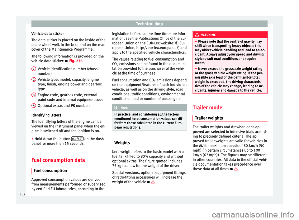
Vehicle data sticker
The d at
a s
ticker is placed on the inside of the
spare wheel well, in the boot and on the rear
cover of the Maintenance Programme.
The following information is provided on the
vehicle data sticker: ››› Fig. 236
Vehicle identification number (chassis
number)
Vehicle type, model, capacity, engine
type, finish, engine power and gearbox
type
Engine code, gearbox code, external
paint code and internal equipment code
Optional extras and PR numbers
Identifying letters
The identifying letters of the engine can be
viewed on the instrument panel when the en-
gine is switched off and the ignition is on.
● Hold down the button 0.0/SET on the dash
p anel
f
or more than 15 seconds.
Fuel consumption data Fuel c
onsumption Approved consumption values are derived
fr
om me
a
surements performed or supervised
by certified EU laboratories, according to the 1 2
3
4 legislation in force at the time (for more infor-
m
ation, see the P
ub
lications Office of the Eu-
ropean Union on the EUR-Lex website: © Eu-
ropean Union, http://eur-lex.europa.eu/) and
apply to the specified vehicle characteristics.
The values relating to fuel consumption and
CO 2 emissions can be found in the documen-
tation provided to the purchaser of the vehi-
cle at the time of purchase.
Fuel consumption and CO 2 emissions depend
on the equipment/features of each individual
vehicle, as well as on the driving style, road
conditions, traffic conditions, environmental
conditions, load or number of passengers. Note
In practice, and considering all the factors
mentioned here, c on
sumption values can dif-
fer from those calculated in the current Euro-
pean regulations. Weights
Kerb weight refers to the basic model with a
f
uel
t
ank filled to 90% capacity and without
optional extras. The figure quoted includes
75 kg to allow for the weight of the driver.
Special versions, optional equipment fittings
or retro-fitting accessories will increase the
weight of the vehicle ››› . WARNING
● Ple a
se note that the centre of gravity may
shift when transporting heavy objects; this
may affect vehicle handling and lead to an ac-
cident. Always adjust your speed and driving
style to suit road conditions and require-
ments.
● Never exceed the gross axle weight rating
or the gros
s vehicle weight rating. If the per-
missible axle load or the permissible total
weight is exceeded, the driving characteris-
tics of the vehicle may change, leading to ac-
cidents, injuries and damage to the vehicle. Trailer mode
Tr
ai
ler weights The trailer weights and drawbar loads ap-
pr
o
v
ed are selected in intensive trials accord-
ing to precisely defined criteria. The ap-
proved trailer weights are valid for vehicles in
the EU for maximum speeds of 80 km/h (50
mph) (in certain circumstances up to 100
km/h (62 mph)). The figures may be different
in other countries. All data in the official vehi-
cle documentation takes precedence over
these data at all times ››› .
282