coolant temperature Seat Ibiza 2017 Owner's manual Edition 11.17
[x] Cancel search | Manufacturer: SEAT, Model Year: 2017, Model line: Ibiza, Model: Seat Ibiza 2017Pages: 312, PDF Size: 6.51 MB
Page 42 of 312
The essentialsMenuFunction
Speed warning
at --- km/h or
Speed warning
at --- mphIf the stored speed is exceeded
(between 30 - 250 km/h, or 19 -
155 mph), an audible warning is
given together with a visual warn-
ing.
Oil tempera-
tureUpdated engine oil temperature
digital display
Coolant tem-
perature gaugeDigital display of the current tem-
perature of the liquid coolant.
Convenience
consumersInformation about the vehicle’s
main convenience consumers. It
is displayed by means of a con-
sumption indicator bar.
Eco tipsTips on how to save fuel.
Reset data “when setting
off”Reset journey data when setting
off.
Reset data for“total calcu-
lation”Reset travel journey to zero. Storing a speed with the speed warning
● Select the display Speed warning at
--- km/h (---
mph)
● Press the button
on the windscreen
w iper l
ev
er or the button on the multifunc-
tion s t
eerin
g wheel to store the current speed
and activate the warning.
● To switch system on: adjust to the desired
speed within 5 sec
onds using the rocker switch
on the windscreen wiper lever or
b y
t
urning the thumbwheel on the multifunc-
tion steering wheel. Next, press the button or
again or wait several seconds.
The s peed i
s
stored and the warning activa-
ted.
● To switch system off: press the but-
ton or
. The stored speed is de-
l et
ed.
Assist systems menu
MenuFunction
ACCDisplay of Adaptive Cruise Control
(ACC) ››› page 216.
Front AssistSwitching the monitoring system
on and off ››› page 212.
Fatigue detec-
tion *Switching the fatigue detection
on or off (pause recommenda-
tion) ››› page 227. Status display
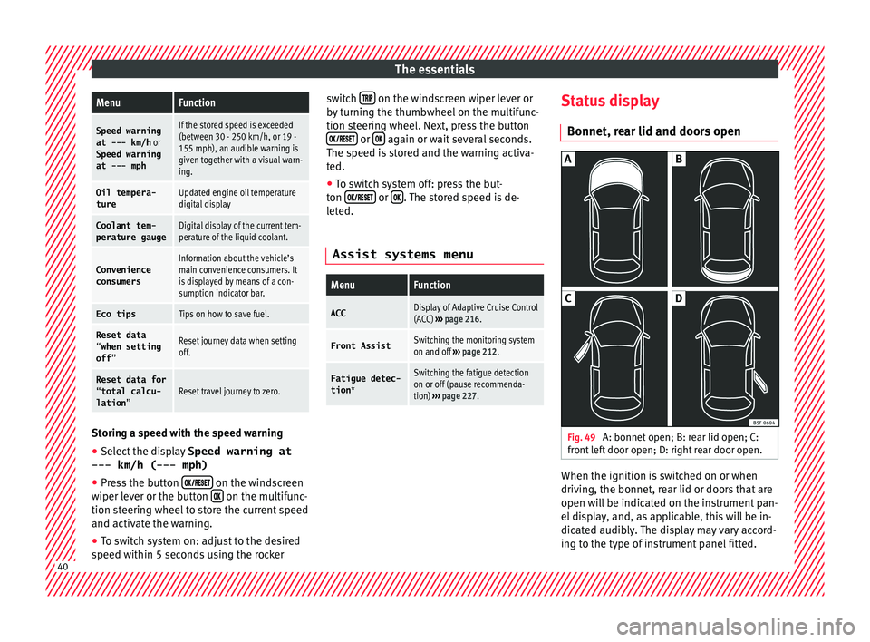
Bonnet, r e
ar lid and door
s open Fig. 49
A: bonnet open; B: rear lid open; C:
fr ont
l
eft door open; D: right rear door open. When the ignition is switched on or when
driv
in
g, the bonnet, r
ear lid or doors that are
open will be indicated on the instrument pan-
el display, and, as applicable, this will be in-
dicated audibly. The display may vary accord-
ing to the type of instrument panel fitted. 40
Page 51 of 312
The essentials
Ignition: Do not carry on
driving! Engine coolant level
too low, coolant temperature
too high
››› page
269
Flashing: Fault in the engine
coolant system.
Do not continue driving!
Engine oil pressure too low.››› page
267
Fault in the battery.›››
page
272
Driving light totally or partially
faulty.›››
page
106
Fault in the cornering light sys-
tem.››› page
149
particulate filter blocked.›››
page
202
Flashing: Fault in the oil level
detection. Control manually.
›››
page
267
Ignition: Insufficient engine
oil.
Fault in the gearbox.›››
page
196
Immobiliser active.›››
page
177
Service interval display›››
page 43
Mobile telephone is connected
via Bluetooth to the original
telephone device.›››
page
124
››› page
129
››› Booklet
Audio or
navigation
system
Mobile telephone battery
charge meter. Available only
for devices pre-installed in fac-
tory.
Freezing warning. The outside
temperature is lower than
+4°C (+39°F).›››
page 41
Start-Stop system activated.›››
page
204
Start-Stop system unavailable.
Low consumption driving sta-
tus›››
page
225
›››
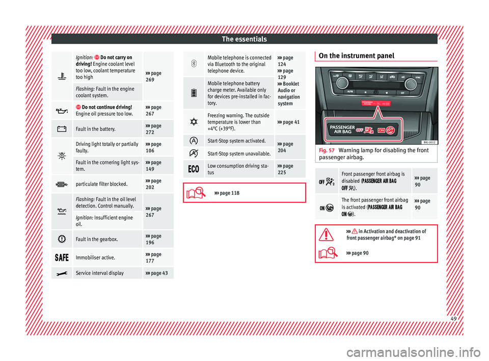
page 118 On the instrument panel
Fig. 57
Warning lamp for disabling the front
p a
s
senger airbag.
Front passenger front airbag is
disabled (
).
››› page
90
The front passenger front airbag
is activated (
).
››› page
90
››› in Activation and deactivation of
front passenger airbag* on page 91
››› page 90 49
Page 62 of 312
The essentials
If for weather reasons further protection is
nec e
s
sary, the proportion of additive may be
increased, but only up to 60 %; otherwise an-
tifreeze protection will diminish and this will
worsen cooling.
When the coolant is topped up, use a mixture
of distilled water and at least 40 % of the
G13 or G12 plus-plus (TL-VW 774 G) additive
(both are purple) to obtain an optimum anti-
corrosion protection ››› in Topping up cool-
ant on p ag
e 271
. The mixture of G13 with
G12 plus (TL-VW 774 F), G12 (red) or G11
(green-blue) engine coolants will significant-
ly reduce anti-corrosion protection and
should therefore be avoided ››› in Topping
up c oo
l
ant on page 271.
››› in Topping up coolant on page 270
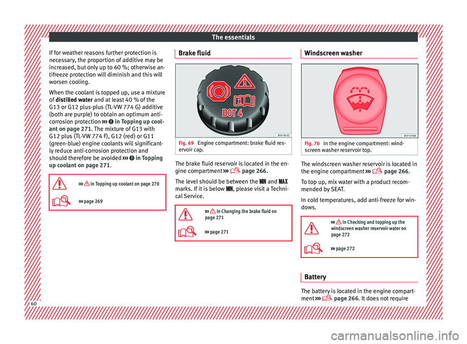
››› page 269 Brake fluid
Fig. 69
Engine compartment: brake fluid res-
er v
oir c
ap. The brake fluid reservoir is located in the en-
gine c
omp
ar
tment ›››
page 266
.
The level should be between the and
marks. If it is below , please visit a Techni-
cal Service.
››› in Changing the brake fluid on
page 271
››› page 271 Windscreen washer
Fig. 70
In the engine compartment: wind-
s c
r
een washer reservoir top. The windscreen washer reservoir is located in
the en
gine c
omp
artment ›››
page 266.
To top up, mix water with a product recom-
mended by SEAT.
In cold temperatures, add anti-freeze for win-
dows.
››› in Checking and topping up the
windscreen washer reservoir water on
page 272
››› page 272 Battery
The battery is located in the engine compart-
ment
›
›
› page 266. It does not require60
Page 107 of 312
Fuses and bulbsNo.Consumer/Amps
13Lights switch, steering column LSS
and SMLS, diagnostic port, rain/light
sensor7.5
14steering column LSS: wiper controls10
15Instrument panel7.5
16Right Lights Power Supply40
17Right Door Window Control30
18Windscreen wipers30
19Radio, Multimedia System25
20Heated Rear Window30
21SCR Control Unit30
23Rear View Camera7.5
24Connectivity Box, external audio
source wiring (Double USB-Aux IN),
telephone amplifier, MIB display5
25Steering Column Electronics (MFL)7.5
26Gateway7.5
27Active Suspension Control Unit7.5
28DWA Sensor7.5
29DWA Horn7.5
319AA/9AB climate control unit7.5
9AK Climatronic control unit15
32Steering Column LSS, without Kessy7.5
No.Consumer/Amps
33Left Door Window Control30
35Left Lights Power Supply40
36Signal Horn20
37Heated seats control unit30
38BCM Power C6330
39BSD, PDC, MRR10
40
Lights switch, diagnostic port, head-
light range control, steering column
LSS: lights, halogen headlights, re-
verse light switch, electrochromic mir-
ror, RKA without radio
7.5
41Regulation of unfolded exterior mir-
rors7.5
42Clutch pedal, ignition relays, CNG re-
lay coil, AC sensor pressure7.5
43DWP relay coil, rear window wiper mo-
tor, heated nozzles15
44Airbag7.5
45Leimo Plus left headlight7.5
46Leimo Plus right headlight7.5
48Steering Column Lock, Kessy Control
Unit7.5
49SCR Relay Coil7.5
53Automatic gearbox lever, ZSS7.5
No.Consumer/Amps
58Double Water Pump7.5
59Heated rear view mirrors10
60Tow Hook30
61Tow Hook30
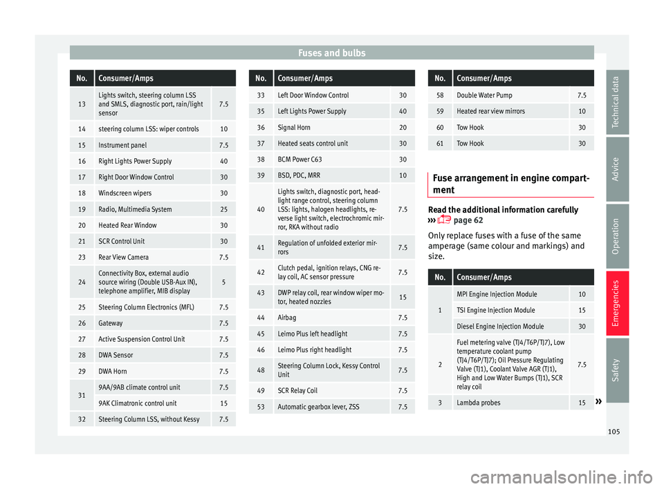
Fuse arrangement in engine compart-
ment
Read the additional information carefully
› ›
›
page 62
Only replace fuses with a fuse of the same
amperage (same colour and markings) and
size.
No.Consumer/Amps
1
MPI Engine Injection Module10
TSI Engine Injection Module15
Diesel Engine Injection Module30
2
Fuel metering valve (TJ4/T6P/TJ7), Low
temperature coolant pump
(TJ4/T6P/TJ7); Oil Pressure Regulating
Valve (TJ1), Coolant Valve AGR (TJ1),
High and Low Water Bumps (TJ1), SCR
relay coil
7.5
3Lambda probes15» 105
Technical data
Advice
Operation
Emergencies
Safety
Page 122 of 312
Operation
Note
● Differ ent
versions of the instrument panel
are available and therefore the versions and
instructions on the display may vary. In the
case of displays without warning or informa-
tion texts, faults are indicated exclusively by
the warning lamps.
● Depending on the equipment, some set-
tings
and instructions can also be carried out
in the Easy Connect system.
● When several warnings are active at the
same time, the symbol
s are shown succes-
sively for a few seconds and will stay on until
the fault is rectified. Odometer
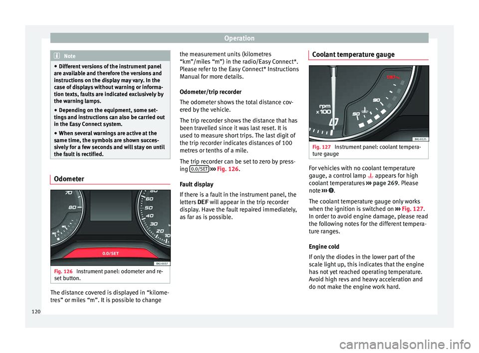
Fig. 126
Instrument panel: odometer and re-
set b
utt
on. The distance covered is displayed in “kilome-
tr
e
s” or mi
les “m”. It is possible to change the measurement units (kilometres
“km”/mile
s “m”) in the radio/Easy Connect*.
Please refer to the Easy Connect* Instructions
Manual for more details.
Odometer/trip recorder
The odometer shows the total distance cov-
ered by the vehicle.
The trip recorder shows the distance that has
been travelled since it was last reset. It is
used to measure short trips. The last digit of
the trip recorder indicates distances of 100
metres or tenths of a mile.
The trip recorder can be set to zero by press-
ing 0.0/SET
› ›
› Fig. 126
.
Fault display
If there is a fault in the instrument panel, the
letters DEF will appear in the trip recorder
display. Have the fault repaired immediately,
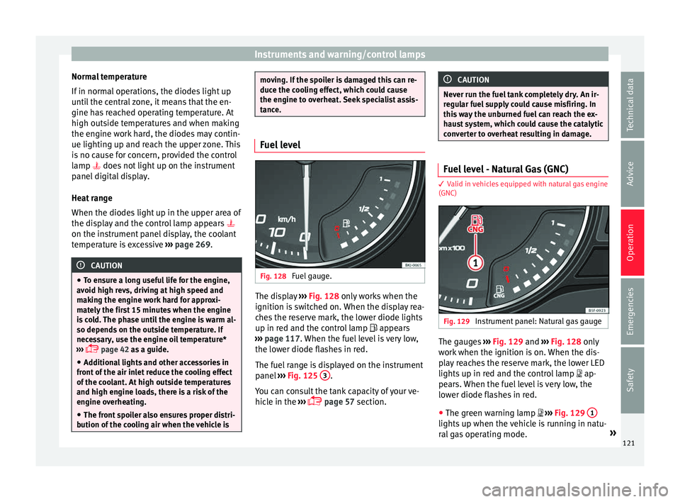
as far as is possible. Coolant temperature gauge Fig. 127
Instrument panel: coolant tempera-
t ur
e g
auge For vehicles with no coolant temperature
g
aug
e, a c
ontrol lamp appears for high
coolant temperatures ››› page 269. Please
note ››› .
The c oo
l
ant temperature gauge only works
when the ignition is switched on ››› Fig. 127.
In order to avoid engine damage, please read
the following notes for the different tempera-
ture ranges.
Engine cold
If only the diodes in the lower part of the
scale light up, this indicates that the engine
has not yet reached operating temperature.
Avoid high revs and heavy acceleration and
do not make the engine work hard.
120
Page 123 of 312
Instruments and warning/control lamps
Normal temperature
If in norm
al
operations, the diodes light up
until the central zone, it means that the en-
gine has reached operating temperature. At
high outside temperatures and when making
the engine work hard, the diodes may contin-
ue lighting up and reach the upper zone. This
is no cause for concern, provided the control
lamp does not light up on the instrument
panel digital display.
Heat range
When the diodes light up in the upper area of
the display and the control lamp appears
on the instrument panel display, the coolant
temperature is excessive ››› page 269. CAUTION
● To en s
ure a long useful life for the engine,
avoid high revs, driving at high speed and
making the engine work hard for approxi-
mately the first 15 minutes when the engine
is cold. The phase until the engine is warm al-
so depends on the outside temperature. If
necessary, use the engine oil temperature*
››› page 42 as a guide.
● Additional lights and other accessories in
front of
the air inlet reduce the cooling effect
of the coolant. At high outside temperatures
and high engine loads, there is a risk of the
engine overheating.
● The front spoiler also ensures proper distri-
bution of the c
ooling air when the vehicle is moving. If the spoiler is damaged this can re-
duce the c
oo
ling effect, which could cause
the engine to overheat. Seek specialist assis-
tance. Fuel level
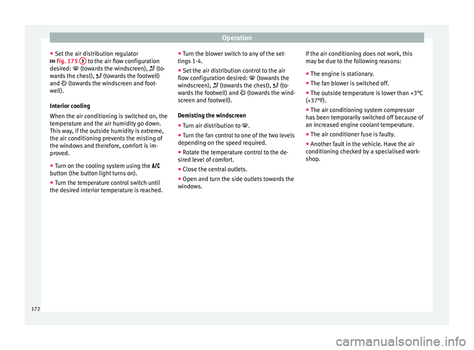
Fig. 128
Fuel gauge. The display
››
› Fig. 128
only works when the
ignition is switched on. When the display rea-
ches the reserve mark, the lower diode lights
up in red and the control lamp appears
››› page 117. When the fuel level is very low,
the lower diode flashes in red.
The fuel range is displayed on the instrument
panel ››› Fig. 125 3 .
Y ou c
an c
onsult the tank capacity of your ve-
hicle in the ›››
page 57 section. CAUTION
Never run the fuel tank completely dry. An ir-
re gu
lar fuel supply could cause misfiring. In
this way the unburned fuel can reach the ex-
haust system, which could cause the catalytic
converter to overheat resulting in damage. Fuel level - Natural Gas (GNC)
3 Valid in vehicles equipped with natural gas engine
(GNC) Fig. 129
Instrument panel: Natural gas gauge The gauges
››
›
Fig. 129 and ›››
Fig. 128 only
work when the ignition is on. When the dis-
play reaches the reserve mark, the lower LED
lights up in red and the control lamp
ap-
pears. When the fuel level is very low, the
lower diode flashes in red.
● The green warning lamp
››
›
Fig. 129 1 lights up when the vehicle is running in natu-
r
al
g
as operating mode. »
121
Technical data
Advice
Operation
Emergencies
Safety
Page 174 of 312
Operation
● Set the air di
s
tribution regulator
››› Fig. 175 3 to the air flow configuration
de s
ir
ed: (towards the windscreen), (to-
wards the chest), (towards the footwell)
and (towards the windscreen and foot-
well).
Interior cooling
When the air conditioning is switched on, the
temperature and the air humidity go down.
This way, if the outside humidity is extreme,
the air conditioning prevents the misting of
the windows and therefore, comfort is im-
proved.
● Turn on the cooling system using the
butt
on (the button light turns on).
● Turn the temperature control switch until
the desir
ed interior temperature is reached. ●
Turn the blo
wer switch to any of the set-
tings 1-4.
● Set the air distribution control to the air
flow configur
ation desired: (towards the
windscreen), (towards the chest), (to-
wards the footwell) and (towards the wind-
screen and footwell).
Demisting the windscreen
● Turn air distribution to .
● Turn the fan control to one of the two levels
depending on the speed r
equired.
● Rotate the temperature control to the de-
sired l
evel of comfort.
● Close the central outlets.
● Open and turn the side outlets towards the
window
s. If the air conditioning does not work, this
may
be due to the following reasons:
● The engine is stationary.
● The fan blower is switched off.
● The outside temperature is lower than +3°C
(+37°F).
● The air conditioning system compressor
has
been temporarily switched off because of
an increased engine coolant temperature.
● The air conditioner fuse is faulty.
● Another fault in the vehicle. Have the air
conditioning c
hecked by a specialised work-
shop.
172
Page 175 of 312
Air conditioning
Climatronic* Gener a
l
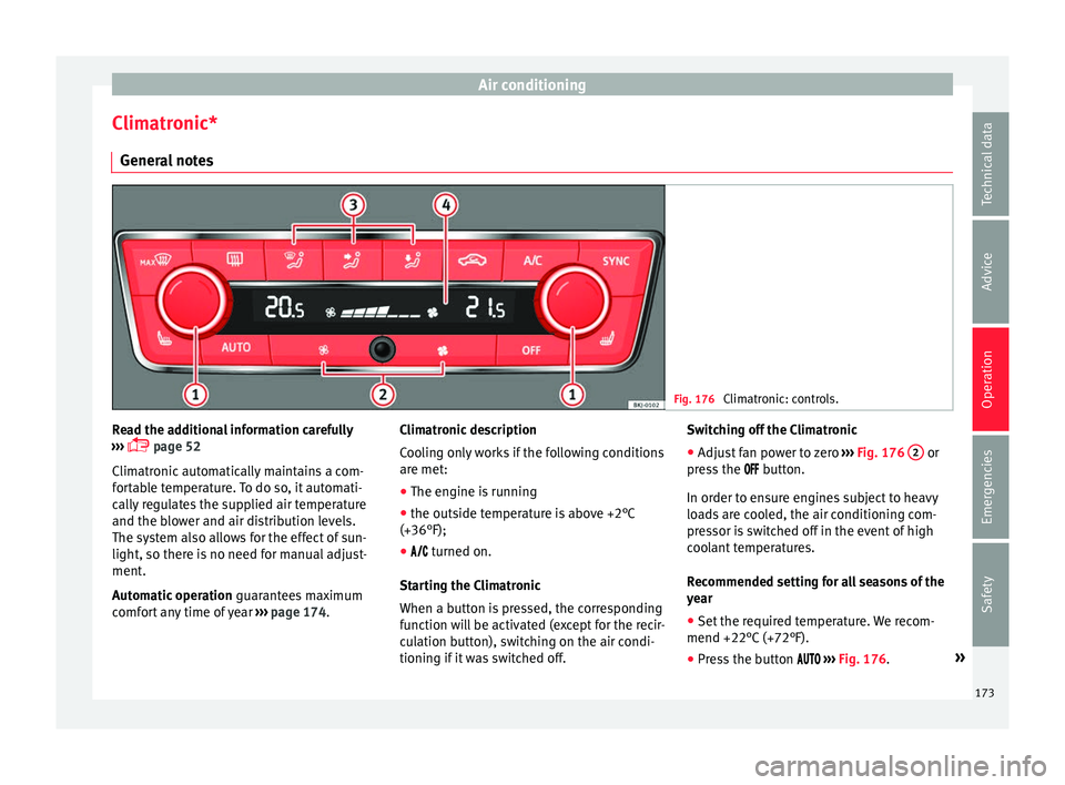
notes Fig. 176
Climatronic: controls. Read the additional information carefully
› ›
›
page 52
Climatronic automatically maintains a com-
fortable temperature. To do so, it automati-
cally regulates the supplied air temperature
and the blower and air distribution levels.
The system also allows for the effect of sun-
light, so there is no need for manual adjust-
ment.
Automatic operation guarantees maximum
comfort any time of year ››› page 174. Climatronic description
Coolin
g only works if the following conditions
are met:
● The engine is running
● the outside temperature is above +2°C
(+36°F);
● turned on.
Star
ting the Climatronic
When a button is pressed, the corresponding
function will be activated (except for the recir-
culation button), switching on the air condi-
tioning if it was switched off. Switching off the Climatronic
●
Adjust fan power to zero ›››
Fig. 176 2 or
pr e
s
s the button.
In order to ensure engines subject to heavy
loads are cooled, the air conditioning com-
pressor is switched off in the event of high
coolant temperatures.
Recommended setting for all seasons of the
year
● Set the required temperature. We recom-
mend +22°C (+72°F).
● Pre
ss the button ››
› Fig. 176. »
173
Technical data
Advice
Operation
Emergencies
Safety
Page 179 of 312
Driving
●
Bef or
e attempting to push-start or tow a ve-
hicle in order to start it, you should first try to
start it using the battery of another vehicle.
Please observe and follow the notes on the
››› page 71, How to jump start. For the sake of the environment
Do not warm-up the engine by running the
en gine w ith the
vehicle stationary. You
should drive off as soon as you start the en-
gine. This helps the engine reach operating
temperature faster and reduces emissions. “SAFE” electronic immobiliser
1)The electronic immobiliser prevents unau-
thori
sed per
son
s from driving the vehicle.
Inside the key there is a chip that deactivates
the electronic immobiliser automatically
when the key is inserted into the ignition.
The electronic immobiliser will be activated
again automatically as soon as you pull the
key out of the ignition lock.
The engine can only be started using a genu-
ine SEAT key with its correct code.
If the following message* is shown on the in-
strument panel display: SAFE, the vehicle
cannot be started. The engine can, however, be started if the
appropri
ate coded SEAT genuine key is used. Note
A perfect operation of the vehicle is ensured
if g enuine
SEAT keys are used. Switching off the engine
–
Stop the vehicle.
– Turn the ignition key to position ›
› ›
Fig. 177
1 .
Af t
er sw
itching the engine off, the radiator
fan may run on for up to 10 minutes. It is also
possible that the fan turns itself on once
more if the coolant temperature increases
due to the heat accumulated in the engine
compartment or due to its prolonged expo-
sure to solar radiation. WARNING
● Never sw it
ch the engine off until the vehi-
cle is completely stationary.
● The brake servo works only when the en-
gine is ru
nning. With the engine switched off,
more strength is needed to brake. As normal
brake operation cannot be performed, risk of
accidents and serious injury may exist. ●
The st eerin
g lock can be immediately
blocked once the key is removed from the ig-
nition. The vehicle cannot be steered. Risk of
accident.
● Power-assisted steering does not work
when the engine is
off, and more strength is
needed to turn the wheel.
● If the key is removed from the ignition lock
the steerin
g lock could be engaged and vehi-
cle steering would not work. CAUTION
● When the en gine ha
s been running under a
heavy load for a long period, heat can accu-
mulate in the engine compartment and cause
engine damage. For this reason, idle the en-
gine for approximately 2 minutes before
switching it off.
● If the vehicle is stopped and the Start-Stop
syst
em* switches off the engine, the ignition
remains switched on. Make sure that the igni-
tion is switched off before leaving the vehi-
cle, otherwise the battery could discharge. 1)
Available depending on the market
177
Technical data
Advice
Operation
Emergencies
Safety
Page 247 of 312
Towing bracket device
Anti-theft alarm When the vehicle is locked, the alarm is trig-
ger
ed when the el
ectrical connection be-
tween vehicle and trailer is interrupted.
Always turn off the anti-theft alarm system
before connecting or disconnecting a trailer
››› page 138.
Conditions for the integration of a trailer in
the anti-theft alarm system.
● The vehicle is factory-equipped with an an-
ti-theft al
arm system and a towing bracket
device.
● The trailer is connected electrically to the
tow
ing vehicle by the trailer connector.
● The electrical system of the vehicle and the
trail
er are prepared for operation.
● The vehicle is locked with the ignition key
and the anti-theft al
arm system is activated.CAUTION
For technical reasons, trailers fitted with rear
LED lights ar
e not integrated in the anti-theft
alarm system. Driving tips
Driving with a trailer always requires extra
c
ar e. W
eight distribution
The weight di
stribution of a loaded trailer
with an unladen vehicle is very unfavourable.
However, if this cannot be avoided, drive ex-
tra slowly to allow for the unbalanced weight
distribution.
Speed
The stability of the vehicle and trailer is re-
duced with increasing speed. For this reason,
it is advisable not to drive at the maximum
permissible speed in an unfavourable road,
weather or wind conditions. This applies es-
pecially when driving downhill.
You should always reduce speed immediately
if the trailer shows the slightest sign of snak-
ing. Never try to stop the “snaking” by in-
creasing speed.
Always brake in due course. If the trailer has
an overrun brake, apply the brakes gently at
first and then, firmly. This will prevent the
jerking that can be caused by locking of trail-
er wheels. Select a low gear in due course
before going down a steep downhill. This en-
ables you to use the engine braking to slow
down the vehicle.
Reheating
At very high temperatures and during pro-
longed slopes, driving in a low gear and high
engine speed, always monitor the coolant
temperature gauge ››› page 120. Electronic Stability Control*
The ESC* sys
tem helps to stabilise the trailer
in case of skidding or rocking.
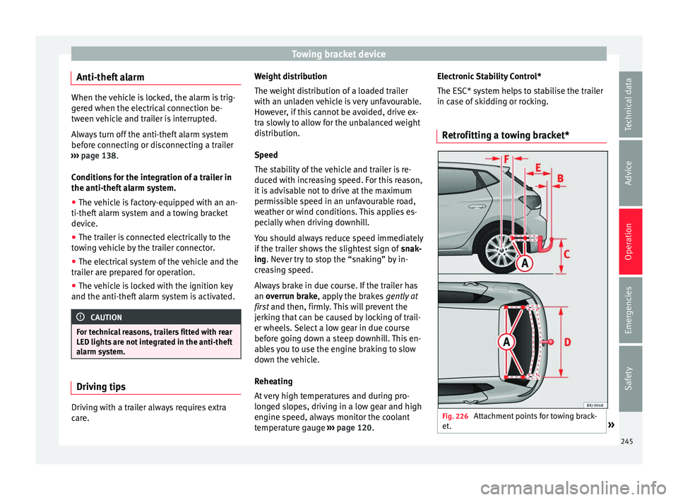
Retrofitting a towing bracket* Fig. 226
Attachment points for towing brack-
et . » 245
Technical data
Advice
Operation
Emergencies
Safety