engine coolant Seat Ibiza 2017 Owner's manual Edition 11.17
[x] Cancel search | Manufacturer: SEAT, Model Year: 2017, Model line: Ibiza, Model: Seat Ibiza 2017Pages: 312, PDF Size: 6.51 MB
Page 6 of 312
Frequently Asked Ques-
tion
sBefore driving
How do you adjust the seat?
››› page 19
How do you adjust the steering wheel? ››› page 20
How do you adjust the exterior mirrors? ››› page 20
How do you turn on the exterior lights? ››› page 31
How does the automatic gearbox selector lever work?
››› page 50
How do you refuel? ››› page 57
How do you activate the windscreen wipers and wind-
screen washer system? ››› page 33
Emergency situations
A warning lamp lights up or flashes. What does this
mean? ››› page 47
Where are the first-aid kit and the warning triangle in
the vehicle? ››› page 97
How do you open the bonnet? ››› page 17
How do you perform a jump start? ››› page 71
Where is the vehicle tool kit located? ››› page 65
How do you repair a tyre with the anti-puncture kit?
››› page 64
How do you change a wheel? ››› page 65
How do you change a fuse? ››› page 62
How do you change a light? ››› page 63
How do you tow a vehicle? ››› page 70
Useful tips
How do you set the time? ››› page 118
When should the vehicle inspection should be per-
formed? ››› page 43
What functions do the buttons/thumbwheels on the
steering wheel perform? ››› page 124
How do you remove the luggage compartment cover?
››› page 163
How do you drive in an economical and environmental-
ly-friendly way? ››› page 200
How do you check and top up the engine oil?
››› page 58
How do you check and top up the engine coolant?
››› page 59
How do you top up the windscreen washer fluid?
››› page 60
How do you check and top up the brake fluid?
››› page 60
How do you check and adjust tyre pressure values?
››› page 275
Vehicle washing tips ››› page 249
Functions of interest
Easy Connect, CAR menu ››› page 34
How does the START-STOP system work? ››› page 204
What parking assistants are available? ››› page 228
How does the rear assist work? ››› page 234
How does the adaptive cruise control work?
››› page 216
How can the SEAT driving mode be adjusted?
››› page 225
How does tyre pressure monitoring work? ››› page 278
How do you open the vehicle without a key (Keyless Ac-
cess)? ››› page 135
Interior lighting and ambient light ››› page 150
Page 42 of 312
The essentialsMenuFunction
Speed warning
at --- km/h or
Speed warning
at --- mphIf the stored speed is exceeded
(between 30 - 250 km/h, or 19 -
155 mph), an audible warning is
given together with a visual warn-
ing.
Oil tempera-
tureUpdated engine oil temperature
digital display
Coolant tem-
perature gaugeDigital display of the current tem-
perature of the liquid coolant.
Convenience
consumersInformation about the vehicle’s
main convenience consumers. It
is displayed by means of a con-
sumption indicator bar.
Eco tipsTips on how to save fuel.
Reset data “when setting
off”Reset journey data when setting
off.
Reset data for“total calcu-
lation”Reset travel journey to zero. Storing a speed with the speed warning
● Select the display Speed warning at
--- km/h (---
mph)
● Press the button
on the windscreen
w iper l
ev
er or the button on the multifunc-
tion s t
eerin
g wheel to store the current speed
and activate the warning.
● To switch system on: adjust to the desired
speed within 5 sec
onds using the rocker switch
on the windscreen wiper lever or
b y
t
urning the thumbwheel on the multifunc-
tion steering wheel. Next, press the button or
again or wait several seconds.
The s peed i
s
stored and the warning activa-
ted.
● To switch system off: press the but-
ton or
. The stored speed is de-
l et
ed.
Assist systems menu
MenuFunction
ACCDisplay of Adaptive Cruise Control
(ACC) ››› page 216.
Front AssistSwitching the monitoring system
on and off ››› page 212.
Fatigue detec-
tion *Switching the fatigue detection
on or off (pause recommenda-
tion) ››› page 227. Status display
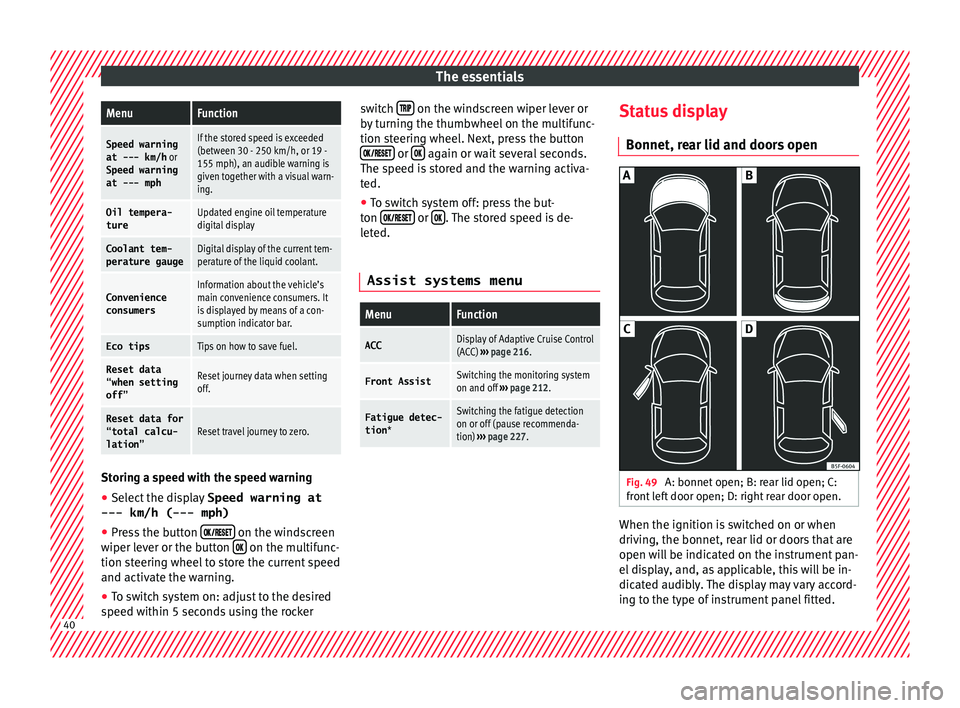
Bonnet, r e
ar lid and door
s open Fig. 49
A: bonnet open; B: rear lid open; C:
fr ont
l
eft door open; D: right rear door open. When the ignition is switched on or when
driv
in
g, the bonnet, r
ear lid or doors that are
open will be indicated on the instrument pan-
el display, and, as applicable, this will be in-
dicated audibly. The display may vary accord-
ing to the type of instrument panel fitted. 40
Page 51 of 312
The essentials
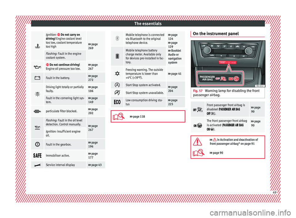
Ignition: Do not carry on
driving! Engine coolant level
too low, coolant temperature
too high
››› page
269
Flashing: Fault in the engine
coolant system.
Do not continue driving!
Engine oil pressure too low.››› page
267
Fault in the battery.›››
page
272
Driving light totally or partially
faulty.›››
page
106
Fault in the cornering light sys-
tem.››› page
149
particulate filter blocked.›››
page
202
Flashing: Fault in the oil level
detection. Control manually.
›››
page
267
Ignition: Insufficient engine
oil.
Fault in the gearbox.›››
page
196
Immobiliser active.›››
page
177
Service interval display›››
page 43
Mobile telephone is connected
via Bluetooth to the original
telephone device.›››
page
124
››› page
129
››› Booklet
Audio or
navigation
system
Mobile telephone battery
charge meter. Available only
for devices pre-installed in fac-
tory.
Freezing warning. The outside
temperature is lower than
+4°C (+39°F).›››
page 41
Start-Stop system activated.›››
page
204
Start-Stop system unavailable.
Low consumption driving sta-
tus›››
page
225
›››
page 118 On the instrument panel
Fig. 57
Warning lamp for disabling the front
p a
s
senger airbag.
Front passenger front airbag is
disabled (
).
››› page
90
The front passenger front airbag
is activated (
).
››› page
90
››› in Activation and deactivation of
front passenger airbag* on page 91
››› page 90 49
Page 61 of 312
The essentials
Engine oil specificationsService intervalEngine typeSpecification
Petrol engines with Set Service Intervals (dependent on
time/distance travelled)1.0l / 1.0l GNC / 1.5lVW 504 00
1.0l / 1.6lVW 502 00 a)
Petrol engines with Flexible Service Intervals (LongLife)1.0l / 1.5lVW 508 00
VW 504 00b)
Diesel engines with Set Service and Flexible Service In-
tervalsc)With particulate filter (DPF)VW 507 00
a)
If the quality of the fuel available in the country does not fulfil the EN 228 (for petrol) and EN 590 (for diesel) standards.
b) Use of engine oil compliant with the VW 504 00 specification instead of VW 508 00 may have a slight negative effect on the vehicle’s exhaust gas values.
c) Only use recommended oils, otherwise you may damage the engine.
››› in Changing engine oil on page 269
››› page 266 Coolant
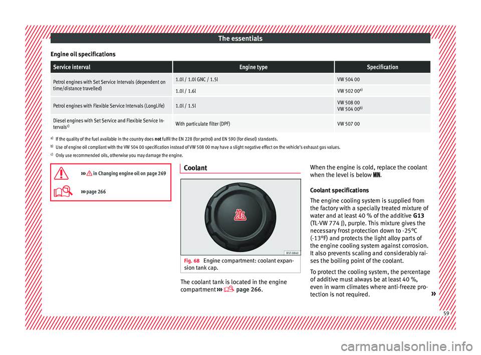
Fig. 68
Engine compartment: coolant expan-
s ion t
ank
cap. The coolant tank is located in the engine
c
omp
ar
tment ›››
page 266. When the engine is cold, replace the coolant
when the level
is below .
Coolant specifications
The engine cooling system is supplied from
the factory with a specially treated mixture of
water and at least 40 % of the additive G13
(TL-VW 774 J), purple. This mixture gives the
necessary frost protection down to -25°C
(-13°F) and protects the light alloy parts of
the engine cooling system against corrosion.
It also prevents scaling and considerably rai-
ses the boiling point of the coolant.
To protect the cooling system, the percentage
of additive must always be at least 40 %,
even in warm climates where anti-freeze pro-
tection is not required. » 59
Page 62 of 312
The essentials
If for weather reasons further protection is
nec e
s
sary, the proportion of additive may be
increased, but only up to 60 %; otherwise an-
tifreeze protection will diminish and this will
worsen cooling.
When the coolant is topped up, use a mixture
of distilled water and at least 40 % of the
G13 or G12 plus-plus (TL-VW 774 G) additive
(both are purple) to obtain an optimum anti-
corrosion protection ››› in Topping up cool-
ant on p ag
e 271
. The mixture of G13 with
G12 plus (TL-VW 774 F), G12 (red) or G11
(green-blue) engine coolants will significant-
ly reduce anti-corrosion protection and
should therefore be avoided ››› in Topping
up c oo
l
ant on page 271.
››› in Topping up coolant on page 270
››› page 269 Brake fluid
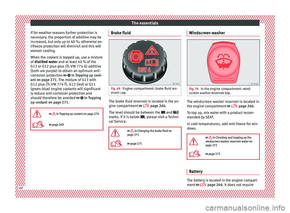
Fig. 69
Engine compartment: brake fluid res-
er v
oir c
ap. The brake fluid reservoir is located in the en-
gine c
omp
ar
tment ›››
page 266
.
The level should be between the and
marks. If it is below , please visit a Techni-
cal Service.
››› in Changing the brake fluid on
page 271
››› page 271 Windscreen washer
Fig. 70
In the engine compartment: wind-
s c
r
een washer reservoir top. The windscreen washer reservoir is located in
the en
gine c
omp
artment ›››
page 266.
To top up, mix water with a product recom-
mended by SEAT.
In cold temperatures, add anti-freeze for win-
dows.
››› in Checking and topping up the
windscreen washer reservoir water on
page 272
››› page 272 Battery
The battery is located in the engine compart-
ment
›
›
› page 266. It does not require60
Page 107 of 312
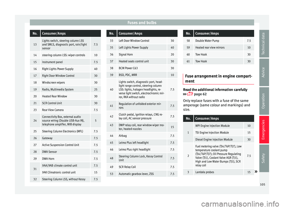
Fuses and bulbsNo.Consumer/Amps
13Lights switch, steering column LSS
and SMLS, diagnostic port, rain/light
sensor7.5
14steering column LSS: wiper controls10
15Instrument panel7.5
16Right Lights Power Supply40
17Right Door Window Control30
18Windscreen wipers30
19Radio, Multimedia System25
20Heated Rear Window30
21SCR Control Unit30
23Rear View Camera7.5
24Connectivity Box, external audio
source wiring (Double USB-Aux IN),
telephone amplifier, MIB display5
25Steering Column Electronics (MFL)7.5
26Gateway7.5
27Active Suspension Control Unit7.5
28DWA Sensor7.5
29DWA Horn7.5
319AA/9AB climate control unit7.5
9AK Climatronic control unit15
32Steering Column LSS, without Kessy7.5
No.Consumer/Amps
33Left Door Window Control30
35Left Lights Power Supply40
36Signal Horn20
37Heated seats control unit30
38BCM Power C6330
39BSD, PDC, MRR10
40
Lights switch, diagnostic port, head-
light range control, steering column
LSS: lights, halogen headlights, re-
verse light switch, electrochromic mir-
ror, RKA without radio
7.5
41Regulation of unfolded exterior mir-
rors7.5
42Clutch pedal, ignition relays, CNG re-
lay coil, AC sensor pressure7.5
43DWP relay coil, rear window wiper mo-
tor, heated nozzles15
44Airbag7.5
45Leimo Plus left headlight7.5
46Leimo Plus right headlight7.5
48Steering Column Lock, Kessy Control
Unit7.5
49SCR Relay Coil7.5
53Automatic gearbox lever, ZSS7.5
No.Consumer/Amps
58Double Water Pump7.5
59Heated rear view mirrors10
60Tow Hook30
61Tow Hook30
Fuse arrangement in engine compart-
ment
Read the additional information carefully
› ›
›
page 62
Only replace fuses with a fuse of the same
amperage (same colour and markings) and
size.
No.Consumer/Amps
1
MPI Engine Injection Module10
TSI Engine Injection Module15
Diesel Engine Injection Module30
2
Fuel metering valve (TJ4/T6P/TJ7), Low
temperature coolant pump
(TJ4/T6P/TJ7); Oil Pressure Regulating
Valve (TJ1), Coolant Valve AGR (TJ1),
High and Low Water Bumps (TJ1), SCR
relay coil
7.5
3Lambda probes15» 105
Technical data
Advice
Operation
Emergencies
Safety
Page 122 of 312
Operation
Note
● Differ ent
versions of the instrument panel
are available and therefore the versions and
instructions on the display may vary. In the
case of displays without warning or informa-
tion texts, faults are indicated exclusively by
the warning lamps.
● Depending on the equipment, some set-
tings
and instructions can also be carried out
in the Easy Connect system.
● When several warnings are active at the
same time, the symbol
s are shown succes-
sively for a few seconds and will stay on until
the fault is rectified. Odometer
Fig. 126
Instrument panel: odometer and re-
set b
utt
on. The distance covered is displayed in “kilome-
tr
e
s” or mi
les “m”. It is possible to change the measurement units (kilometres
“km”/mile
s “m”) in the radio/Easy Connect*.
Please refer to the Easy Connect* Instructions
Manual for more details.
Odometer/trip recorder
The odometer shows the total distance cov-
ered by the vehicle.
The trip recorder shows the distance that has
been travelled since it was last reset. It is
used to measure short trips. The last digit of
the trip recorder indicates distances of 100
metres or tenths of a mile.
The trip recorder can be set to zero by press-
ing 0.0/SET
› ›
› Fig. 126
.
Fault display
If there is a fault in the instrument panel, the
letters DEF will appear in the trip recorder
display. Have the fault repaired immediately,
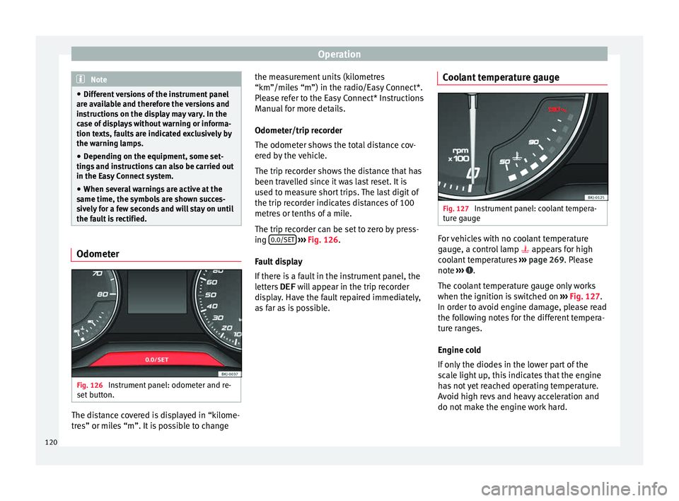
as far as is possible. Coolant temperature gauge Fig. 127
Instrument panel: coolant tempera-
t ur
e g
auge For vehicles with no coolant temperature
g
aug
e, a c
ontrol lamp appears for high
coolant temperatures ››› page 269. Please
note ››› .
The c oo
l
ant temperature gauge only works
when the ignition is switched on ››› Fig. 127.
In order to avoid engine damage, please read
the following notes for the different tempera-
ture ranges.
Engine cold
If only the diodes in the lower part of the
scale light up, this indicates that the engine
has not yet reached operating temperature.
Avoid high revs and heavy acceleration and
do not make the engine work hard.
120
Page 123 of 312
Instruments and warning/control lamps
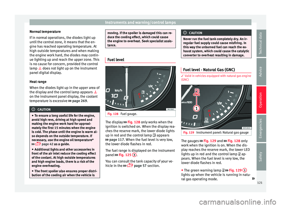
Normal temperature
If in norm
al
operations, the diodes light up
until the central zone, it means that the en-
gine has reached operating temperature. At
high outside temperatures and when making
the engine work hard, the diodes may contin-
ue lighting up and reach the upper zone. This
is no cause for concern, provided the control
lamp does not light up on the instrument
panel digital display.
Heat range
When the diodes light up in the upper area of
the display and the control lamp appears
on the instrument panel display, the coolant
temperature is excessive ››› page 269. CAUTION
● To en s
ure a long useful life for the engine,
avoid high revs, driving at high speed and
making the engine work hard for approxi-
mately the first 15 minutes when the engine
is cold. The phase until the engine is warm al-
so depends on the outside temperature. If
necessary, use the engine oil temperature*
››› page 42 as a guide.
● Additional lights and other accessories in
front of
the air inlet reduce the cooling effect
of the coolant. At high outside temperatures
and high engine loads, there is a risk of the
engine overheating.
● The front spoiler also ensures proper distri-
bution of the c
ooling air when the vehicle is moving. If the spoiler is damaged this can re-
duce the c
oo
ling effect, which could cause
the engine to overheat. Seek specialist assis-
tance. Fuel level
Fig. 128
Fuel gauge. The display
››
› Fig. 128
only works when the
ignition is switched on. When the display rea-
ches the reserve mark, the lower diode lights
up in red and the control lamp appears
››› page 117. When the fuel level is very low,
the lower diode flashes in red.
The fuel range is displayed on the instrument
panel ››› Fig. 125 3 .
Y ou c
an c
onsult the tank capacity of your ve-
hicle in the ›››
page 57 section. CAUTION
Never run the fuel tank completely dry. An ir-
re gu
lar fuel supply could cause misfiring. In
this way the unburned fuel can reach the ex-
haust system, which could cause the catalytic
converter to overheat resulting in damage. Fuel level - Natural Gas (GNC)
3 Valid in vehicles equipped with natural gas engine
(GNC) Fig. 129
Instrument panel: Natural gas gauge The gauges
››
›
Fig. 129 and ›››
Fig. 128 only
work when the ignition is on. When the dis-
play reaches the reserve mark, the lower LED
lights up in red and the control lamp
ap-
pears. When the fuel level is very low, the
lower diode flashes in red.
● The green warning lamp
››
›
Fig. 129 1 lights up when the vehicle is running in natu-
r
al
g
as operating mode. »
121
Technical data
Advice
Operation
Emergencies
Safety
Page 124 of 312
Operation
● The gr een w
arnin
g lamp 1 turns off
when the n at
ur
al gas is exhausted. The en-
gine changes to operate with petrol.
● The yellow control lamp lights up when
the re
serve level has been reached.
Things to note
If the vehicle is left parked for a long time im-
mediately after refuelling, the natural gas lev-
el indicator may not accurately indicate the
same level shown after refuelling when the
vehicle is started up again. This is not due to
a leak in the system, but to a drop in pres-
sure in the gas tank for technical reasons af-
ter a cooling phase just after refuelling.
Warning and control lamps
Warning symbo
lsRead the additional information carefully
› ›
›
page 47
There are red warning symbols (priority 1)
and yellow warning symbols (priority 2).
Warning messages, Priority 1 (red)
If one of these faults occurs, the warning
lamp will light up or flash and will be accom-
panied by three audible warnings. This is a
danger warning. Stop the vehicle and switch off the engine. Check the fault and correct it.
Obtain pr
ofessional assistance if necessary.
If several priority 1 faults are detected at the
same time, the symbols will be displayed one
after the other for about 2 seconds at a time
and will continue until the fault is corrected.
No menus will be shown in the display for the
duration of a priority 1 warning message.
Examples of priority 1 warning messages
(red)
● Brake system symbol with the warnin
g
message STOP BRAKE FLUID INSTRUC-
TION MANUAL or STOP BRAKE FAULT IN-
STRUCTION MANUAL .
● Coolant symbol with the warnin
g mes-
sage STOP SEE COOLANT INSTRUCTION
MANUAL .
● Engine oil pressure symbol with the
warnin
g message STOP ENGINE OIL
PRESSURE LOW! INSTRUCTION MANUAL .
Warning messages, Priority 2 (yellow)
If one of these faults occurs, the correspond-
ing warning lamp lights up and is accompa-
nied by an audible warning. Check the corre-
sponding function as soon as possible al-
though the vehicle may be used without risk.
If several priority 2 warning messages are de-
tected at the same time, the symbols are dis-
played one after the other for about 2 sec- onds at a time. After a set time, the informa-
tion text
will disappear and the symbol will
be shown as a reminder at the side of the
display.
Priority 2 warning messages will not be
shown until all Priority 1 warning messages
have been dealt with!
Examples of priority 2 warning reports (yel-
low):*
● Fuel warning light with the information text
PLEASE REFUEL . WARNING
If the warning lamps and messages are ignor-
ed, the v ehic
le may stall in traffic, or may
cause accidents and severe injuries.
● Never ignore the warning lamps or text
mess
ages.
● Stop the vehicle safely as soon as possible.
● Park the vehicle away from traffic and en-
sure th
at there are no highly flammable ma-
terials under the vehicle that could come into
contact with the exhaust system (e.g. dry
grass, fuel).
● A faulty vehicle represents a risk of acci-
dent for the driv
er and for other road users. If
necessary, switch on the hazard warning
lamps and put out the warning triangle to ad-
vise other drivers.
● Before opening the bonnet, switch off the
engine and al
low it to cool.122
Page 174 of 312
Operation
● Set the air di
s
tribution regulator
››› Fig. 175 3 to the air flow configuration
de s
ir
ed: (towards the windscreen), (to-
wards the chest), (towards the footwell)
and (towards the windscreen and foot-
well).
Interior cooling
When the air conditioning is switched on, the
temperature and the air humidity go down.
This way, if the outside humidity is extreme,
the air conditioning prevents the misting of
the windows and therefore, comfort is im-
proved.
● Turn on the cooling system using the
butt
on (the button light turns on).
● Turn the temperature control switch until
the desir
ed interior temperature is reached. ●
Turn the blo
wer switch to any of the set-
tings 1-4.
● Set the air distribution control to the air
flow configur
ation desired: (towards the
windscreen), (towards the chest), (to-
wards the footwell) and (towards the wind-
screen and footwell).
Demisting the windscreen
● Turn air distribution to .
● Turn the fan control to one of the two levels
depending on the speed r
equired.
● Rotate the temperature control to the de-
sired l
evel of comfort.
● Close the central outlets.
● Open and turn the side outlets towards the
window
s. If the air conditioning does not work, this
may
be due to the following reasons:
● The engine is stationary.
● The fan blower is switched off.
● The outside temperature is lower than +3°C
(+37°F).
● The air conditioning system compressor
has
been temporarily switched off because of
an increased engine coolant temperature.
● The air conditioner fuse is faulty.
● Another fault in the vehicle. Have the air
conditioning c
hecked by a specialised work-
shop.
172