heating Seat Ibiza 5D 2015 Owner's manual
[x] Cancel search | Manufacturer: SEAT, Model Year: 2015, Model line: Ibiza 5D, Model: Seat Ibiza 5D 2015Pages: 248, PDF Size: 4.77 MB
Page 5 of 248
Table of Contents
Table of Contents
The e s
senti
als . . . . . . . . . . . . . . . . . . . . . . . . 5
Exterior view . . . . . . . . . . . . . . . . . . . . . . . . . . . . 5
Exterior view . . . . . . . . . . . . . . . . . . . . . . . . . . . . 6
Interior view (left guide) . . . . . . . . . . . . . . . . . . 7
Interior view (right-hand drive) . . . . . . . . . . . . . 8
How it works . . . . . . . . . . . . . . . . . . . . . . . . . . . . 9
Opening and closing . . . . . . . . . . . . . . . . . . . . . 9
Before driving . . . . . . . . . . . . . . . . . . . . . . . . . . . 12
Airbags . . . . . . . . . . . . . . . . . . . . . . . . . . . . . . . . 14
Child seats . . . . . . . . . . . . . . . . . . . . . . . . . . . . . 16
Starting the vehicle . . . . . . . . . . . . . . . . . . . . . . 20
Lights and visibility . . . . . . . . . . . . . . . . . . . . . . 21
Easy Connect . . . . . . . . . . . . . . . . . . . . . . . . . . . 24
Driver information system . . . . . . . . . . . . . . . . . 25
Journey data . . . . . . . . . . . . . . . . . . . . . . . . . . . . 29
Cruise control . . . . . . . . . . . . . . . . . . . . . . . . . . . 34
Warning lamps . . . . . . . . . . . . . . . . . . . . . . . . . . 35
Gearbox lever . . . . . . . . . . . . . . . . . . . . . . . . . . . 37
Air conditioning . . . . . . . . . . . . . . . . . . . . . . . . . 39
Level control . . . . . . . . . . . . . . . . . . . . . . . . . . . . 40
Emergencies . . . . . . . . . . . . . . . . . . . . . . . . . . . . 44
Fuses . . . . . . . . . . . . . . . . . . . . . . . . . . . . . . . . . . 44
Bulbs . . . . . . . . . . . . . . . . . . . . . . . . . . . . . . . . . . 45
Action in the event of a puncture . . . . . . . . . . . 45
Changing a wheel . . . . . . . . . . . . . . . . . . . . . . . 47
Snow chains . . . . . . . . . . . . . . . . . . . . . . . . . . . . 50
Emergency towing of the vehicle . . . . . . . . . . . 51
How to jump start . . . . . . . . . . . . . . . . . . . . . . . . 52
Changing the windscreen wiper blades . . . . . . 54
Safety . . . . . . . . . . . . . . . . . . . . . . . . . . . . . . . . 56
Safe driving . . . . . . . . . . . . . . . . . . . . . . . . . . . . 56
Safety first! . . . . . . . . . . . . . . . . . . . . . . . . . . . . . 56
Advice about driving . . . . . . . . . . . . . . . . . . . . . 56 Correct position for passengers . . . . . . . . . . . . 57
Pedal area . . . . . . . . . . . . . . . . . . . . . . . . . . . . . . 61
Seat belts
. . . . . . . . . . . . . . . . . . . . . . . . . . . . . . 61
Why wear a seat belt? . . . . . . . . . . . . . . . . . . . . 61
How to properly adjust your seatbelt . . . . . . . . 64
Belt pretensioners* . . . . . . . . . . . . . . . . . . . . . . 65
Airbag system . . . . . . . . . . . . . . . . . . . . . . . . . . 66
Brief introduction . . . . . . . . . . . . . . . . . . . . . . . . 66
Airbag safety instructions . . . . . . . . . . . . . . . . . 69
Deactivating airbags . . . . . . . . . . . . . . . . . . . . . 70
Transporting children safely . . . . . . . . . . . . . . . 72
Safety for children . . . . . . . . . . . . . . . . . . . . . . . 72
Child seats . . . . . . . . . . . . . . . . . . . . . . . . . . . . . 73
Emergencies . . . . . . . . . . . . . . . . . . . . . . . . . . 75
Self-help . . . . . . . . . . . . . . . . . . . . . . . . . . . . . . . 75
Emergency equipment . . . . . . . . . . . . . . . . . . . . 75
Tyre repair . . . . . . . . . . . . . . . . . . . . . . . . . . . . . . 76
Changing the windscreen wiper blades . . . . . . 78
Towing or tow-starting . . . . . . . . . . . . . . . . . . . . 79
Fuses and bulbs . . . . . . . . . . . . . . . . . . . . . . . . . 81
Fuses . . . . . . . . . . . . . . . . . . . . . . . . . . . . . . . . . . 81
Changing bulbs . . . . . . . . . . . . . . . . . . . . . . . . . 83
Single headlight bulb change . . . . . . . . . . . . . . 84
Double headlight bulb change . . . . . . . . . . . . . 85
Changing the AFS headlight bulbs . . . . . . . . . . 87
Changing the fog light bulbs . . . . . . . . . . . . . . . 88
Changing the tail light bulbs . . . . . . . . . . . . . . . 89
Changing the side and interior bulbs . . . . . . . . 91
Operation . . . . . . . . . . . . . . . . . . . . . . . . . . . . . 95
Controls and displays . . . . . . . . . . . . . . . . . . . . 95
General instrument panel . . . . . . . . . . . . . . . . . 94
Instruments and warning/control lamps . . . . . 96
Instruments . . . . . . . . . . . . . . . . . . . . . . . . . . . . 96
Warning and indication lamps . . . . . . . . . . . . . 100
Introduction to the Easy Connect system* . . . . 107
System settings (CAR)* . . . . . . . . . . . . . . . . . . . 107 Communications and multimedia
. . . . . . . . . . . 108
Steering wheel controls* . . . . . . . . . . . . . . . . . . 108
Multimedia . . . . . . . . . . . . . . . . . . . . . . . . . . . . . 112
Opening and closing . . . . . . . . . . . . . . . . . . . . . 112
Central locking system . . . . . . . . . . . . . . . . . . . . 112
Keys . . . . . . . . . . . . . . . . . . . . . . . . . . . . . . . . . . . 116
Radio frequency remote control* . . . . . . . . . . . 117
Anti-theft alarm* . . . . . . . . . . . . . . . . . . . . . . . . 118
Boot hatch . . . . . . . . . . . . . . . . . . . . . . . . . . . . . 120
Electric windows . . . . . . . . . . . . . . . . . . . . . . . . . 120
Tilting panoramic roof* . . . . . . . . . . . . . . . . . . . 122
Lights and visibility . . . . . . . . . . . . . . . . . . . . . . 123
Lights . . . . . . . . . . . . . . . . . . . . . . . . . . . . . . . . . 123
Interior lights . . . . . . . . . . . . . . . . . . . . . . . . . . . 128
Visibility . . . . . . . . . . . . . . . . . . . . . . . . . . . . . . . 128
Windscreen wiper and rear window wiper sys-
tems . . . . . . . . . . . . . . . . . . . . . . . . . . . . . . . . . . 129
R
ear view mirrors . . . . . . . . . . . . . . . . . . . . . . . . 131
Seats and head restraints . . . . . . . . . . . . . . . . . 132
Adjusting the seat and head restraints . . . . . . 132
Seat functions . . . . . . . . . . . . . . . . . . . . . . . . . . 134
Transport and practical equipment . . . . . . . . . 136
Practical equipment . . . . . . . . . . . . . . . . . . . . . . 136
Luggage compartment . . . . . . . . . . . . . . . . . . . . 139
Roof rack/roof luggage rack* . . . . . . . . . . . . . . 142
Air conditioning . . . . . . . . . . . . . . . . . . . . . . . . . 144
Heating, ventilation and cooling . . . . . . . . . . . . 144
Heating and fresh air . . . . . . . . . . . . . . . . . . . . . 146
Air conditioning* . . . . . . . . . . . . . . . . . . . . . . . . 148
Climatronic* . . . . . . . . . . . . . . . . . . . . . . . . . . . . 150
Driving . . . . . . . . . . . . . . . . . . . . . . . . . . . . . . . . 152
Address . . . . . . . . . . . . . . . . . . . . . . . . . . . . . . . . 152
Starting and stopping the engine . . . . . . . . . . . 153
Braking and parking . . . . . . . . . . . . . . . . . . . . . 156
Manual gearbox . . . . . . . . . . . . . . . . . . . . . . . . . 159
Automatic gearbox* . . . . . . . . . . . . . . . . . . . . . . 159
Run-in and economical driving . . . . . . . . . . . . . 165
Driving abroad . . . . . . . . . . . . . . . . . . . . . . . . . . 168 3
Page 23 of 248
The essentials
press the locking key on the selector lever
and r el
e
ase it again.
● Unlocking the steering wheel: Put the key
into the ignition and turn it
at the same time
as the steering wheel in the direction indica-
ted by the arrow. If it is not possible to turn
the steering wheel, it may be because it is
locked.
Turning on/switching off the ignition, glow
plugs reheating
● Switch ignition on: Turn the key to the 2position.
●
Switch ignition off. Turn the key to the 1position.
●
Diesel vehicles : The glo
w p
lugs reheat
when the ignition is switched on
Starting the engine
● Manual gearbox: press the clutch pedal all
the way
down and move the gearbox lever in-
to neutral.
● Automatic gearbox: Press the brake pedal
and move the sel
ector lever to the P position
or into N.
● Turn the key to the 3 position. The key au-
t om
atic
ally returns to the 2 position. Do not
pr e
s
s the accelerator. Start-Stop System*
When you s
top and release the clutch pedal,
the Start-Stop system* turns off the engine.
The ignition remains switched on.
››› in Ignition key positions on
page 154
››› page 153 Lights and visibility
He a
dlight
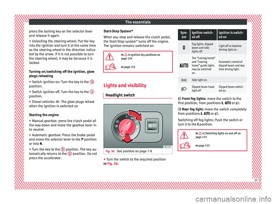
switch Fig. 30
See position on page 7-8 ●
Turn the switch to the required position
› ›
›
Fig. 30.
Sym-
bolIgnition switch-
ed offIgnition is switch-
ed on
Fog lights, dipped
beam and side
lights off.Light off or daytime
driving light on.
The “Coming home”
and “Leaving
home” guide lights
may be switched
on.Automatic control of
dipped beam and day-
time driving light.
Side light on.
Dipped beam head-
light offDipped beam switch-
ed on.
Front
fog lights: mo
ve the switch to the
first position, from positions , or .
Rear fog light: move the switch completely
from positions , or .
Switching off fog lights: Push the switch or
turn it to the position.
››› in Switching lights on and off on
page 123
››› page 123 21
Page 42 of 248
The essentials
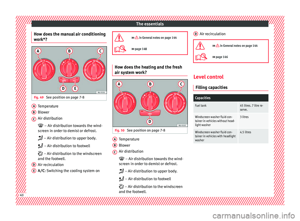
How does the manual air conditioning
w ork*? Fig. 49
See position on page 7-8 Temperature
Blo
w
er
Air di
stribution
– Air distribution towards the wind-
screen in order to demist or defrost.
– Air distribution to upper body.
– Air distribution to footwell
– Air distribution to the windscreen
and the footwell.
Air recirculation
A/C : Switching the cooling system on
A B
C
D
E
››› in General notes on page 144
›››
page 148 How does the heating and the fresh
air sy
s
t
em work? Fig. 50
See position on page 7-8 Temperature
Blo
w
er
Air di
stribution
– Air distribution towards the wind-
screen in order to demist or defrost.
– Air distribution to upper body.
– Air distribution to footwell
– Air distribution to the windscreen
and the footwell.
A B
C Air recirculation
››› in General notes on page 144
››› page 146 Level control
Fi l
lin
g capacities
Capacities
Fuel tank45 litres. 7 litre re-
serve.
Windscreen washer fluid con-
tainer in vehicles without head-
light washer3 litres
Windscreen washer fluid con-
tainer in vehicles with headlight
washer4.5 litres D
40
Page 80 of 248
Emergencies
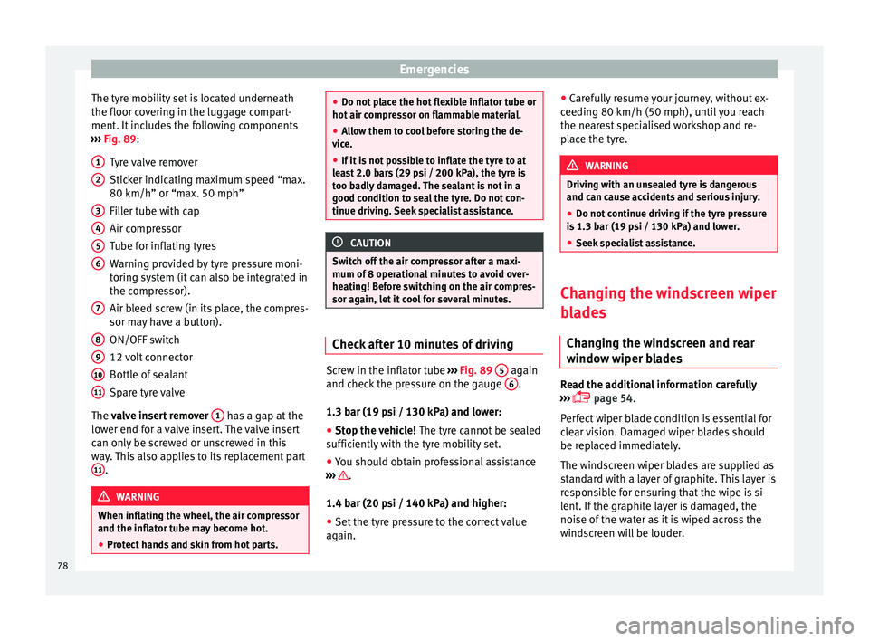
The tyre mobility set is located underneath
the floor c o
v
ering in the luggage compart-
ment. It includes the following components
››› Fig. 89:
Tyre valve remover
Sticker indicating maximum speed “max.
80 km/h” or “max. 50 mph”
Filler tube with cap
Air compressor
Tube for inflating tyres
Warning provided by tyre pressure moni-
toring system (it can also be integrated in
the compressor).
Air bleed screw (in its place, the compres-
sor may have a button).
ON/OFF switch
12 volt connector
Bottle of sealant
Spare tyre valve
The valve insert remover 1 has a gap at the
lo w
er end f
or a valve insert. The valve insert
can only be screwed or unscrewed in this
way. This also applies to its replacement part 11 .
WARNING
When inflating the wheel, the air compressor
and the inflat or t
ube may become hot.
● Protect hands and skin from hot parts. 1
2
3
4
5
6
7
8
9
10
11 ●
Do not p l
ace the hot flexible inflator tube or
hot air compressor on flammable material.
● Allow them to cool before storing the de-
vice.
● If
it is not possible to inflate the tyre to at
lea
st 2.0 bars (29 psi / 200 kPa), the tyre is
too badly damaged. The sealant is not in a
good condition to seal the tyre. Do not con-
tinue driving. Seek specialist assistance. CAUTION
Switch off the air compressor after a maxi-
mum of 8 operation
al minutes to avoid over-
heating! Before switching on the air compres-
sor again, let it cool for several minutes. Check after 10 minutes of driving
Screw in the inflator tube
››
›
Fig. 89 5 again
and c hec
k
the pressure on the gauge 6 .
1.3 b ar (19 p
s
i / 130 kPa) and lower:
● Stop the vehicle! The tyre c
annot be sealed
sufficiently with the tyre mobility set.
● You should obtain professional assistance
›››
.
1.4 b ar (20 p
s
i / 140 kPa) and higher:
● Set the tyre pressure to the correct value
again. ●
Caref
ully resume your journey, without ex-
ceeding 80 km/h (50 mph), until you reach
the nearest specialised workshop and re-
place the tyre. WARNING
Driving with an unsealed tyre is dangerous
and can c au
se accidents and serious injury.
● Do not continue driving if the tyre pressure
is 1.3
bar (19 psi / 130 kPa) and lower.
● Seek specialist assistance. Changing the windscreen wiper
b
l
a
des
Changing the windscreen and rear
window wiper blades Read the additional information carefully
› ›
›
page 54.
Perfect wiper blade condition is essential for
clear vision. Damaged wiper blades should
be replaced immediately.
The windscreen wiper blades are supplied as
standard with a layer of graphite. This layer is
responsible for ensuring that the wipe is si-
lent. If the graphite layer is damaged, the
noise of the water as it is wiped across the
windscreen will be louder.
78
Page 84 of 248
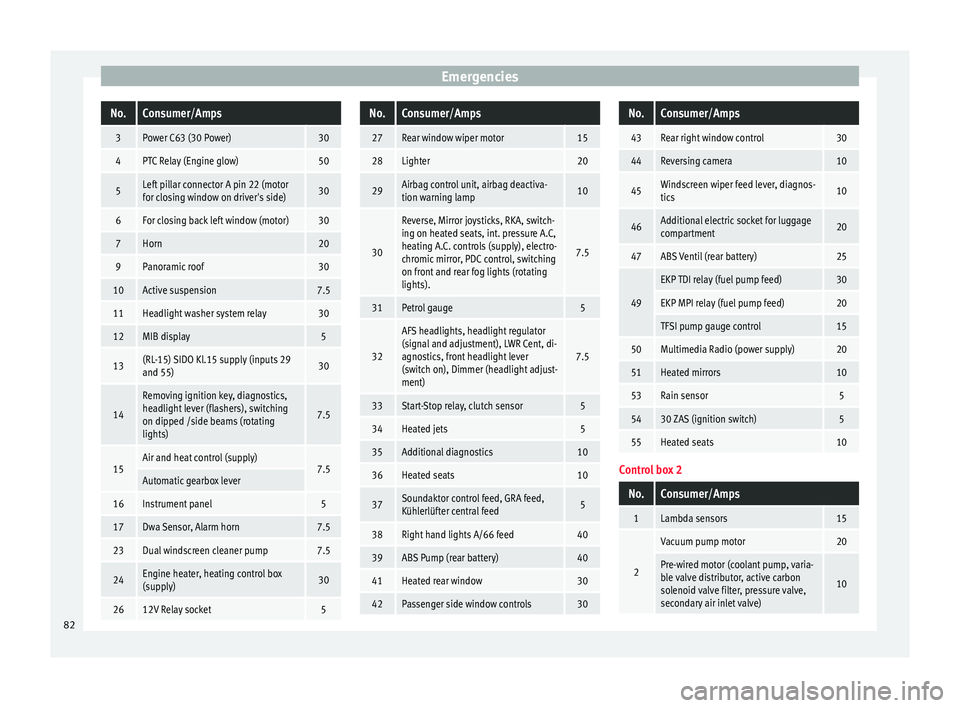
EmergenciesNo.Consumer/Amps
3Power C63 (30 Power)30
4PTC Relay (Engine glow)50
5Left pillar connector A pin 22 (motor
for closing window on driver's side)30
6For closing back left window (motor)30
7Horn20
9Panoramic roof30
10Active suspension7.5
11Headlight washer system relay30
12MIB display5
13(RL-15) SIDO Kl.15 supply (inputs 29
and 55)30
14
Removing ignition key, diagnostics,
headlight lever (flashers), switching
on dipped /side beams (rotating
lights)
7.5
15Air and heat control (supply)7.5Automatic gearbox lever
16Instrument panel5
17Dwa Sensor, Alarm horn7.5
23Dual windscreen cleaner pump7.5
24Engine heater, heating control box
(supply)30
2612V Relay socket5
No.Consumer/Amps
27Rear window wiper motor15
28Lighter20
29Airbag control unit, airbag deactiva-
tion warning lamp10
30
Reverse, Mirror joysticks, RKA, switch-
ing on heated seats, int. pressure A.C,
heating A.C. controls (supply), electro-
chromic mirror, PDC control, switching
on front and rear fog lights (rotating
lights).
7.5
31Petrol gauge5
32
AFS headlights, headlight regulator
(signal and adjustment), LWR Cent, di-
agnostics, front headlight lever
(switch on), Dimmer (headlight adjust-
ment)
7.5
33Start-Stop relay, clutch sensor5
34Heated jets5
35Additional diagnostics10
36Heated seats10
37Soundaktor control feed, GRA feed,
Kühlerlüfter central feed5
38Right hand lights A/66 feed40
39ABS Pump (rear battery)40
41Heated rear window30
42Passenger side window controls30
No.Consumer/Amps
43Rear right window control30
44Reversing camera10
45Windscreen wiper feed lever, diagnos-
tics10
46Additional electric socket for luggage
compartment20
47ABS Ventil (rear battery)25
49
EKP TDI relay (fuel pump feed)30
EKP MPI relay (fuel pump feed)20
TFSI pump gauge control15
50Multimedia Radio (power supply)20
51Heated mirrors10
53Rain sensor5
5430 ZAS (ignition switch)5
55Heated seats10
Control box 2
No.Consumer/Amps
1Lambda sensors15
2
Vacuum pump motor20
Pre-wired motor (coolant pump, varia-
ble valve distributor, active carbon
solenoid valve filter, pressure valve,
secondary air inlet valve)
10
82
Page 97 of 248
Controls and displays
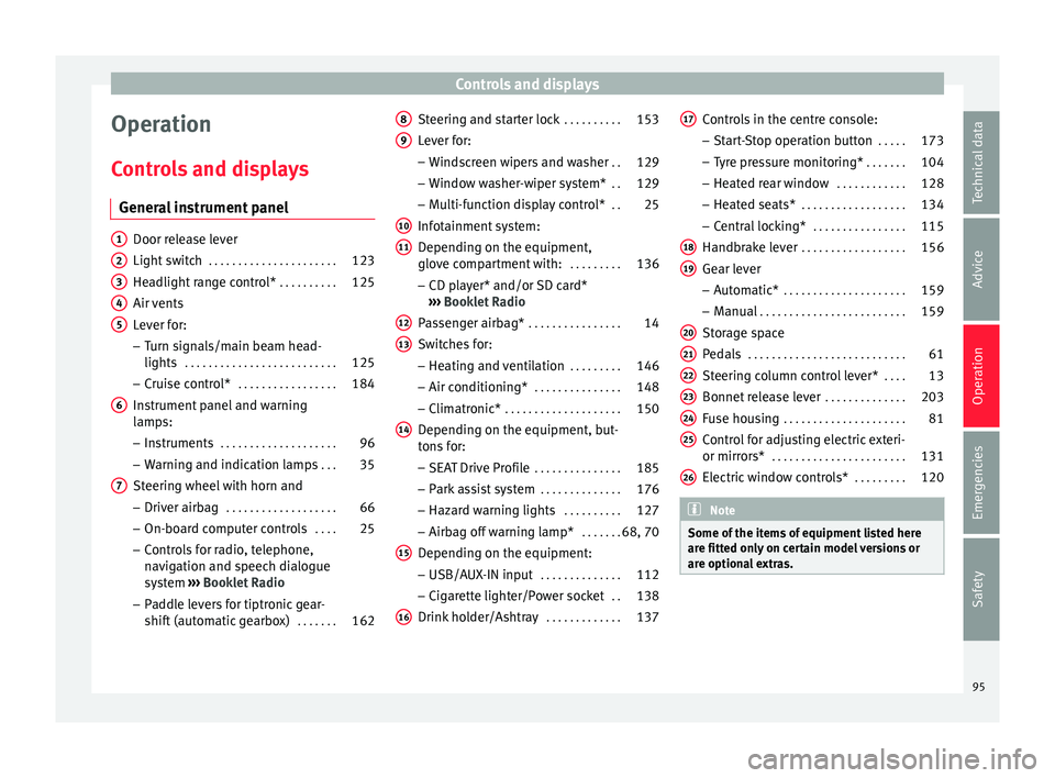
Operation
C ontr
o
ls and displays
General instrument panel Door release lever
Light sw
it
ch . . . . . . . . . . . . . . . . . . . . . . 123
Headlight range control* . . . . . . . . . .125
Air vents
Lever f
or:
– Turn signals/main beam head-
lights . . . . . . . . . . . . . . . . . . . . . . . . . . 125
– Crui se c
ontrol* . . . . . . . . . . . . . . . . . 184
Instrument panel and warning
lamp s:
– In
struments . . . . . . . . . . . . . . . . . . . . 96
– Warnin g and indic
ation lamps . . .35
Steering wheel with horn and – Driver airb ag . . . . . . . . . . . . . . . . . . . 66
– On-boar d c
omputer controls . . . .25
– Contro
ls for radio, telephone,
navigation and speech dialogue
system ›››
Booklet Radio
– Paddle levers for tiptronic gear-
shift (automatic gearbox) . . . . . . .162
1 2
3
4
5
6
7 Steering and starter lock
. . . . . . . . . .153
Lever for: – Wind
s
creen wipers and washer . .129
– Window w
asher-wiper system* . .129
– Multi-f
unction display control* . .25
Infotainment system:
Depending on the equipment,
glo
ve compartment with: . . . . . . . . .136
– CD pla
yer* and/or SD card*
››› Booklet Radio
Passenger airbag* . . . . . . . . . . . . . . . . 14
Switches for:
– Heating and
ventilation . . . . . . . . . 146
– Air conditionin g* . . . . . . . . . . . . . . . 148
– C
limatr
onic* . . . . . . . . . . . . . . . . . . . . 150
Depending on the equipment, but-
ton s
for:
– SEAT Drive Profile . . . . . . . . . . . . . . . 185
– Park a
ssist system . . . . . . . . . . . . . . 176
– Hazard w
arning lights . . . . . . . . . .127
– Airbag off w
arning lamp* . . . . . . .68, 70
Depending on the equipment:
– USB/AUX -IN inp
ut . . . . . . . . . . . . . . 112
– Cig ar
ette lighter/Power socket . .138
Drink holder/Ashtray . . . . . . . . . . . . .137
8 9
10
11
12
13
14
15
16 Controls in the centre console:
– St ar
t
-Stop operation button . . . . .173
– Tyr
e pressure monitoring* . . . . . . .104
– Heated r
ear window . . . . . . . . . . . . 128
– Heated se
ats* . . . . . . . . . . . . . . . . . . 134
– Central
locking* . . . . . . . . . . . . . . . . 115
Handbrake lever . . . . . . . . . . . . . . . . . . 156
Gear lever – Automatic* . . . . . . . . . . . . . . . . . . . . . 159
– M
anual . . . . . . . . . . . . . . . . . . . . . . . . . 159
Stor
age space
Pedal
s . . . . . . . . . . . . . . . . . . . . . . . . . . . 61
Steering column control lever* . . . .13
Bonnet release lever . . . . . . . . . . . . . .203
Fuse housing . . . . . . . . . . . . . . . . . . . . . 81
Control for adjusting electric exteri-
or mirrors* . . . . . . . . . . . . . . . . . . . . . . . 131
El
ectric window controls* . . . . . . . . .120 Note
Some of the items of equipment listed here
are fitt ed on
ly on certain model versions or
are optional extras. 17
18
19
20
21
22
23
24
25
26
95
Technical data
Advice
Operation
Emergencies
Safety
Page 102 of 248
Operation
●
Addition a
l lights and other accessories in
front of the air inlet reduce the cooling effect
of the coolant. At high outside temperatures
and high engine loads, there is a risk of the
engine overheating.
● The front spoiler also ensures proper distri-
bution of the c
ooling air when the vehicle is
moving. If the spoiler is damaged this can re-
duce the cooling effect, which could cause
the engine to overheat. Seek specialist assis-
tance. Fuel level
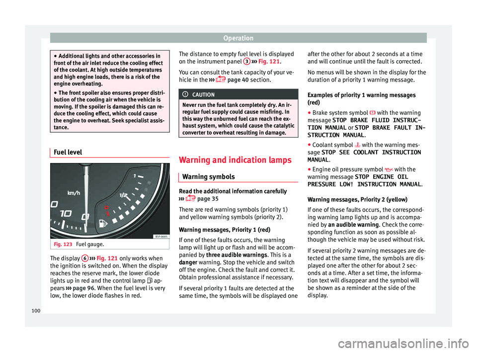
Fig. 123
Fuel gauge. The display
6
› ›
› Fig. 121
only works when
the ignition is switched on. When the display
reaches the reserve mark, the lower diode
lights up in red and the control lamp ap-
pears ››› page 96. When the fuel level is very
low, the lower diode flashes in red. The distance to empty fuel level is displayed
on the instrument
panel 3
› ››
Fig. 121
.
Y
ou can consult the tank capacity of your ve-
hicle in the ›››
page 40 section. CAUTION
Never run the fuel tank completely dry. An ir-
re gu
lar fuel supply could cause misfiring. In
this way the unburned fuel can reach the ex-
haust system, which could cause the catalytic
converter to overheat resulting in damage. Warning and indication lamps
W arnin
g symbo
ls Read the additional information carefully
› ›
›
page 35
There are red warning symbols (priority 1)
and yellow warning symbols (priority 2).
Warning messages, Priority 1 (red)
If one of these faults occurs, the warning
lamp will light up or flash and will be accom-
panied by three audible warnings. This is a
danger warning. Stop the vehicle and switch
off the engine. Check the fault and correct it.
Obtain professional assistance if necessary.
If several priority 1 faults are detected at the
same time, the symbols will be displayed one after the other for about 2 seconds at a time
and wil
l continue until the fault is corrected.
No menus will be shown in the display for the
duration of a priority 1 warning message.
Examples of priority 1 warning messages
(red)
● Brake system symbol with the warnin
g
message STOP BRAKE FLUID INSTRUC-
TION MANUAL or STOP BRAKE FAULT IN-
STRUCTION MANUAL .
● Coolant symbol with the warnin
g mes-
sage STOP SEE COOLANT INSTRUCTION
MANUAL .
● Engine oil pressure symbol with the
warnin
g message STOP ENGINE OIL
PRESSURE LOW! INSTRUCTION MANUAL .
Warning messages, Priority 2 (yellow)
If one of these faults occurs, the correspond-
ing warning lamp lights up and is accompa-
nied by an audible warning. Check the corre-
sponding function as soon as possible al-
though the vehicle may be used without risk.
If several priority 2 warning messages are de-
tected at the same time, the symbols are dis-
played one after the other for about 2 sec-
onds at a time. After a set time, the informa-
tion text will disappear and the symbol will
be shown as a reminder at the side of the
display.
100
Page 103 of 248
Instruments and warning/control lamps
Priority 2 warning messages will not be
sho wn u
ntil all Priority 1 warning messages
have been dealt with!
Examples of priority 2 warning reports (yel-
low):*
● Fuel warning light with the information text
PLEASE REFUEL .WARNING
If the warning lamps and messages are ignor-
ed, the v ehic
le may stall in traffic, or may
cause accidents and severe injuries.
● Never ignore the warning lamps or text
mess
ages.
● Stop the vehicle safely as soon as possible.
● Park the vehicle away from traffic and en-
sure th
at there are no highly flammable ma-
terials under the vehicle that could come into
contact with the exhaust system (e.g. dry
grass, fuel).
● A faulty vehicle represents a risk of acci-
dent for the driv
er and for other road users. If
necessary, switch on the hazard warning
lamps and put out the warning triangle to ad-
vise other drivers.
● Before opening the bonnet, switch off the
engine and al
low it to cool.
● In any vehicle, the engine compartment is a
hazar
dous area and could cause severe inju-
ries ››› page 201. CAUTION
Failure to heed the control lamps and text
mes s
ages when they appear may result in
faults in the vehicle. Engine management*
This warning lamp monitors the engine man-
agement
sy
stem for petrol engines.
The warning lamp (Electronic Power Con-
trol) lights up when the ignition is switched
on while system operation is being verified. It
should go out once the engine is started.
If there is a fault in the electronic engine
management system while you are driving,
this warning lamp will light up. Stop the vehi-
cle and seek technical assistance.
Engine pre-heating/fault system* The warning lamp lights up to show that the
glo
w p
lug
s are preheating the diesel engine.
The control lamp lights up
If the control lamp lights up when the en-
gine is started it means that the glow plugs
are preheating. When the warning lamp goes
off, the engine should be started straight
away. Control lamp
flashe
s
If a fault develops in the engine management
system while you are driving, the glow plug
system lamp will flash . Take the vehicle to
a specialised workshop as soon as possible
and have the engine checked.
Accumulation of soot in the diesel en-
gine partic
ulate filter* If the control lamp
lights up
y
ou should
help the filter clean itself by driving in the ap-
propriate manner.
To do this, drive about 15 minutes in fourth
or fifth gear (automatic gearbox: S gear
range) at a minimum speed of 60 km/h
(37 mph), with the engine running at approxi-
mately 2,000 rpm. In this way, the soot build
up in the filter is burned. When cleaning is
successful, the control lamp turns off.
If the lamp does not turn off, or the three
lamps turn on (particulate filter , fault in
the emission control system and glow
plugs ), drive the vehicle to a specialised
workshop and have the fault repaired at the
earliest opportunity. »
101
Technical data
Advice
Operation
Emergencies
Safety
Page 108 of 248
Operation
●
Never ignor e the w
arning lamps or messag-
es.
● Stop the vehicle at the next opportunity
and in a safe p
lace. Note
Failure to heed the control lamps and corre-
s pondin g t
ext messages when they light up
may result in damage to the vehicle. Emission control system*
Control lamp
fla
she
s:
When there is misfiring that can damage the
catalytic converter. Reduce speed and drive
carefully to the nearest specialised workshop
to have the engine checked.
The control lamp lights up:
If a fault has developed during driving which
has reduced the quality of the exhaust gas
(e.g. lambda probe fault). Reduce speed and
drive carefully to the nearest specialised
workshop to have the engine checked.
Coolant Level*/Temperature There is a fault if:
● The warning symbol does not go out again
af t
er a f
ew seconds. ●
The contro
l lamp lights up or flashes while
the vehicle is moving, and three acoustic
warning signals ››› are emitted.
Thi s
me
ans that either the coolant level is too
low or the coolant temperature is too high.
Coolant temperature too high
If the control lamp comes on, stop the vehi-
cle, turn off the engine and wait for it to cool
down. Check the coolant level.
If the coolant level is correct, the overheating
may be caused by a malfunction of the radia-
tor fan. Check the radiator fan fuse and have
it replaced if necessary ››› page 81.
If the control lamp lights up again after driv-
ing on for a short distance, stop the vehicle
and switch the engine off. Contact a Techni-
cal Service or a specialised workshop.
Coolant level too low
If the control lamp comes on , stop the vehi-
cle, turn off the engine and wait for it to cool
down. First check the coolant level. If the lev-
el of the coolant is below the “MIN” mark,
top up with coolant liquid ››› .
WARNING
● If y
our vehicle is immobilised for technical
reasons, move it to a safe distance from traf-
fic. Turn the engine off, turn the hazard lights
on and place the warning triangle. ●
Never open the bonnet if
you can see or
hear steam or coolant escaping from the en-
gine compartment. Risk of scalding. Wait un-
til you can no longer see or hear escaping
steam or coolant.
● The engine compartment is a dangerous
area. B
efore carrying out any work in the en-
gine compartment, switch off the engine and
allow it to cool down. Always note the corre-
sponding warnings ››› page 201. Alternator
This control lamp signals a fault in the alter-
n
at
or
.
The control lamp lights up when the igni-
tion is switched on. It should go out when the
engine has started running.
If the control lamp lights up while driving,
the alternator is no longer charging the bat-
tery. You should immediately drive to the
nearest specialised workshop.
You should avoid using electrical equipment
that is not absolutely necessary because this
will drain the battery.
Turn signals Depending on which turn signal is operating,
either the l
ef
t
or right turn signal lamp
flashes. Both control lamps will flash at the
106
Page 130 of 248
Operation
All turn signals flash simultaneously when
the h az
ar
d warning lights are switched on.
The two turn signal turn signal lamps
and the turn signal lamp in the switch will
flash at the same time. The hazard warning
lights also work when the ignition is switch-
ed off. WARNING
● The risk of
an accident increases if your ve-
hicle breaks down. Always use the hazard
warning lights and a warning triangle to draw
the attention of other road users to your sta-
tionary vehicle.
● Due to the high temperatures that the cata-
lytic con
verter can reach, never park in an
area where the catalytic converter could come
into contact with highly inflammable materi-
als, for example dry grass or spilt petrol. This
could start a fire. Note
● The batt er
y will run down if the hazard
warning lights are left on for a long time,
even if the ignition is switched off.
● The use of the hazard warning lights de-
scribed her
e is subject to the relevant statu-
tory requirements. Interior lights
Int erior and r
e
ading lights Read the additional information carefully
›› ›
page 22
Luggage compartment lighting
The light is activated when the rear lid is
open, even when the ignition and lights are
turned off. For this reason, ensure that the
rear lid is always closed.
Glove compartment light
When opening the glove compartment on the
passenger side, the glove compartment light
will automatically turn on and will turn off
upon closure.
Ambient light*
››› table on page 2
The ambient lighting lights up the central
console area and the footwell area.
They will switch on fully when the doors are
opened and will decrease in intensity while
driving when the dipped beam headlight is
on.
The intensity of the ambient light* can be ad-
justed using the Easy Connect menu (see
Adjusting Lights > Interior light-
ing ›››
page 24). Note
If not all the vehicle doors are closed, the in-
terior light s
will be switched off after approx.
10 minutes, providing the ignition key has
been removed and the courtesy light position
selected. This prevents the battery from dis-
charging. Visibility
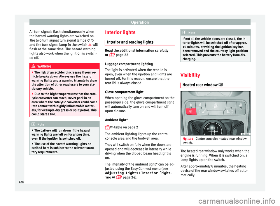
Heat ed r
ear window Fig. 136
Centre console: heated rear window
sw it
c
h. The heated rear window only works when the
en
gine i
s
running. When it is switched on, a
lamp lights up on the switch.
After approximately 8 minutes, the heating
device of the rear window switches off auto-
matically.
128