ESP Seat Ibiza SC 2012 User Guide
[x] Cancel search | Manufacturer: SEAT, Model Year: 2012, Model line: Ibiza SC, Model: Seat Ibiza SC 2012Pages: 280, PDF Size: 3.67 MB
Page 45 of 280
43
Child safety
WARNING
● Never install a child seat facing backwards on the front passenger
seat unless the front passenger front airbag has been disabled. Risk of
potentially fatal injuries to the child! However, if it is necessary, in excep-
tional cases, to transport a child in the front passenger seat, the front
passenger front airbag must always be disabled ⇒ page 40, Deactivating
airbags*. If the front passenger seat has a height adjustment option,
move it to the highest position.
● For those vehicles that do not include a key lock switch to deactivate
the airbag, the vehicle must be taken to a Technical Service.
● All vehicle occupants, especially children, must assume the proper
sitting position and be properly belted in while travelling.
● Never hold children or babies on your lap, this can result in potential-
ly fatal injuries to the child!
● Never allow a child to be transported in a vehicle without being prop-
erly secured, or to stand up or kneel on a seat while travelling. In an acci-
dent, the child could be flung through the vehicle, causing possibly fatal
injuries to themselves and to the other vehicle occupants.
● If children assume an improper sitting position when the vehicle is
moving, they expose themselves to greater risk of injury in the event of a
sudden braking manoeuvre or in an accident. This is particularly impor-
tant if the child is travelling on the front passenger seat and the airbag
system is triggered in an accident; as this could cause serious injury or
even death.
● A suitable child seat can protect your child!
● Never leave an unsupervised child alone on a child seat or in the vehi-
cle.
● Depending on weather conditions, it may become extremely hot or
cold inside the vehicle. This can be fatal.WARNING (Continued)
● Children who are less than 1.5 metres tall must not wear a normal
seat belt without a child seat, as this could cause injuries to the abdomi-
nal and neck areas during a sudden braking manoeuvre or in an accident.
● Do not allow the seat belt to become twisted or jammed, or to rub on
any sharp edges.
● Incorrectly worn seat belts can cause injuries even in a minor colli-
sion or in sudden braking manoeuvres.
● The seat belt provides maximum protection only when the seat belt is
properly positioned ⇒ page 24, Seat belts.
● Only one child may occupy a child seat ⇒ page 44, Child seats.
Safety FirstOperating InstructionsPractical TipsTechnical Specifications
Page 59 of 280
57
Cockpit
WARNING
LPG is a highly explosive and inflammable substance. It may cause se-
vere burns and other injury.
● Due care must be taken to avoid any risk of fire or explosion.
● When parking the vehicle in a closed area (for example in a garage),
make sure that there is adequate ventilation, either natural or mechani-
cal, to neutralise the LPG in the event of a leak.
Note
● The values shown in the average fuel consumption and distance to emp-
ty indications on the multifunction display (MFI) 1)
on the instrument panel 2)
are approximate values only.
● Two different consumption values are given on the MFI, depending on
whether the vehicle is running in GAS or Petrol mode.
● Please check the fuel level on the fuel level gauge on the instrument
panel ⇒ page 57
● If frequent short journeys are made, especially when the outside tem-
perature is low, the vehicle will tend to run on petrol more often than on
LPG. Therefore, the petrol tank may empty before the LPG tank. Digital instrument panel display
Fuel gauge and reserve indicator
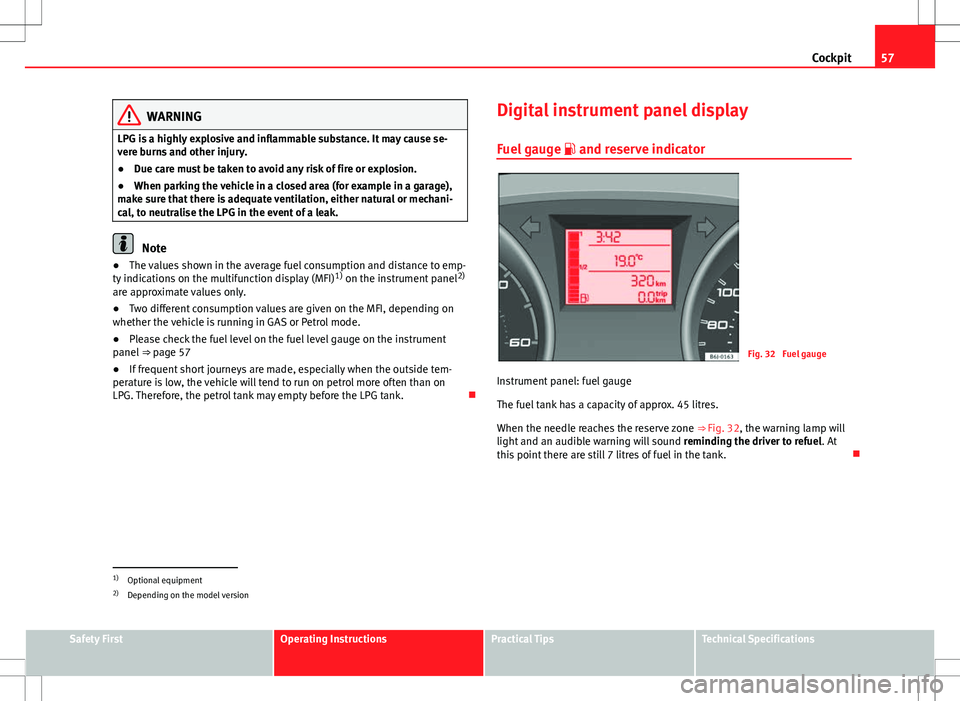
Fig. 32 Fuel gauge
Instrument panel: fuel gauge
The fuel tank has a capacity of approx. 45 litres.
When the needle reaches the reserve zone ⇒ Fig. 32, the warning lamp will
light and an audible warning will sound reminding the driver to refuel. At
this point there are still 7 litres of fuel in the tank.
1)
Optional equipment
2) Depending on the model version
Safety FirstOperating InstructionsPractical TipsTechnical Specifications
Page 64 of 280
62Cockpit
The service interval display only indicates the dates of services that include
engine oil change. The dates of all other services, such as Inspection Serv-
ice or brake fluid change, appear in the sticker on the door pillar or in the
Maintenance Programme.
Vehicles with service intervals dependent on time/distance travelled al-
ready have certain service intervals set.
The intervals are calculated separately in vehicles with LongLife service.
Technical progress has made it possible to considerably reduce servicing re-
quirements. With the LongLife System, SEAT ensures that your vehicle only
has an interval service when it is necessary. To calculate this (max. two
years), the conditions under which the vehicle is used and the individual
driving style are also taken into account. The service pre-warning will ap-
pear at 20 days or less prior to the corresponding service. The distance trav-
elled is rounded off to the nearest 100 km (miles) and the time to full days.
The current service message can only be consulted 500 km (miles) or more
after the last service. Until that time, only dashes are displayed.
Service warning
A service warning will appear when the ignition is switched on if a service is
due soon.
The instrument panel display will show the “spanner symbol” and the
“km (miles)” indication, along with a clock symbol with the days remaining
until the date of the next service. The figure indicated is the maximum num-
ber of kilometres (miles) remaining before the date of the next service. The
indication changes after a few seconds. A “clock symbol” appears and the
number of days until the service appointment should be carried out.
Service
If a service is due, an audible warning will sound and the flashing “span-
ner” symbol will be shown along with the fixed text SERVICE.
If no service is carried out following the indication on the instrument panel,
the excess distance travelled and the excess time following the SERVICE
warning will be displayed. Reading the service message
The current service message
can be consulted with the ignition on, the en-
gine switched off and the vehicle at a standstill:
● Press the
button on the instrument panel as often as necessary until
the spanner symbol is displayed.
An overdue service is indicated by a minus sign in front of the mileage or
day information.
Resetting service interval display
If the service was not performed by a SEAT dealership, the display must be
reset as follows:
● Switch the ignition off.
● Press and hold the 0.0 / SET
button.
● Switch ignition back on.
● Release the 0.0 / SET
button and press the button within 20 seconds.
Do not reset the display between service intervals, as the display will other-
wise be incorrect.
If the display is reset manually, the next service interval will be indicated af-
ter 15 000 km (10 000 miles) or one year and will not be calculated individ-
ually.
Note
In LongLife Service vehicles, if the battery is disconnected for a long period,
the days remaining until the next service cannot be calculated. Therefore,
the service message indications may be incorrect. In this case, bear in mind
the maximum service intervals permitted in the ⇒ Booklet Maintenance Pro-
gramme.
Page 69 of 280
67
Cockpit
If several priority 1 faults are detected at the same time, the symbols will be
displayed one after the other for about 2 seconds at a time and will contin-
ue until the fault is corrected.
No menus will be shown in the display for the duration of a priority 1 warn-
ing message.
Examples of priority 1 warning messages (red)
● Brake system symbol with the warning message STOP BRAKE FLUID
INSTRUCTION MANUAL or STOP BRAKE FAULT INSTRUCTION MANUAL .
● Coolant symbol with the warning message STOP SEE COOLANT IN-
STRUCTION MANUAL.
● Engine oil pressure symbol with the warning message STOP ENGINE
OIL PRESSURE LOW! INSTRUCTION MANUAL .
Warning messages, Priority 2 (yellow)
If one of these faults occurs, the warning lamp lights up, and is accompa-
nied by one audible warning. Check the corresponding function as soon as
possible although the vehicle may be used without risk.
If several priority 2 warning messages are detected at the same time, the
symbols are displayed one after the other for about 2 seconds at a time. Af-
ter a set time, the information text will disappear and the symbol will be
shown as a reminder at the side of the display.
Priority 2 warning messages will not be shown until all Priority 1 warning
messages have been dealt with!
Examples of priority 2 warning messages (yellow): 1)
● Fuel warning light with the information text PLEASE REFUEL. Information messages displayed on the screen*
Message
a)Description
SERVICEThe service interval has ended. Take the vehicle to a Techni-
cal Service.
IMMOBILIS-
ERImmobiliser system active. The vehicle will not start. Take
the vehicle to a Technical Service.
ERRORInstrument panel faulty. Take the vehicle to a Technical Serv-
ice.
CLEAN AIRFILTERWarning: Clean the air filter.
NO KEYWarning: Correct key cannot be found in the vehicle.KEY BATTERYWarning: Key battery low. Change the battery.
CLUTCHWarning: Press the clutch to start. In vehicles with manual
gearbox and Start/Stop system.
--> P/NWarning: Place the selector level in P/N to start. Only in ve-
hicles with automatic gearbox.
--> PWarning: Place the selector lever in position P to stop the
engine.
STARTINGWarning: The engine starts automatically. Start-Stop system
activated.
START MAN- UALLYWarning: The engine must be started manually. Start-Stop
system activated.
ERROR
START STOPWarning: Start-Stop system error.
START-STOP
IMPOSSIBLEWarning: Although the Start-Stop system is switched on, the
engine cannot be stopped automatically. Not all the neces-
sary conditions are met.
START-STOP ACTIVEWarning: Start-Stop system activated. Vehicle in Stop mode.
1)
Depending on the version of the model.
Safety FirstOperating InstructionsPractical TipsTechnical Specifications
Page 74 of 280
72Cockpit
Tyre pressure*
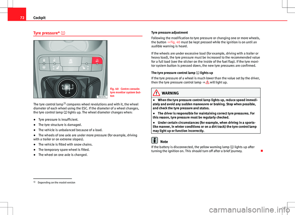
Fig. 40 Centre console:
tyre monitor system but-
ton
The tyre control lamp 1)
compares wheel revolutions and with it, the wheel
diameter of each wheel using the ESC. If the diameter of a wheel changes,
the tyre control lamp lights up. The wheel diameter changes when:
● Tyre pressure is insufficient.
● The tyre structure is damaged.
● The vehicle is unbalanced because of a load.
● The wheels of one axle are under more pressure (for example, driving
with a trailer or on extreme slopes).
● The vehicle is fitted with snow chains.
● The temporary spare wheel is fitted.
● The wheel on one axle is changed. Tyre pressure adjustment
Following the modification to tyre pressure or changing one or more wheels,
the button ⇒ Fig. 40 must be kept pressed while the ignition is on until an
audible warning is heard.
If the wheels are under excessive load (for example, driving with a trailer or
heavy load), the tyre pressure must be increased to the recommended value
for a full load (see the sticker on the inside of the fuel flap). If the tyre moni-
tor system button is pressed down, the new tyre pressures are confirmed.
The tyre pressure control lamp
lights up
If the tyre pressure of a wheel is much lower than the value set by the driver,
then the tyre pressure control lamp ⇒
will light up.
WARNING
● When the tyre pressure control lamp lights up, reduce speed immedi-
ately and avoid any sudden manoeuvre or braking. Stop when possible,
and check the tyre pressure and status.
● The driver is responsible for maintaining correct tyre pressures. For
this reason, tyre pressure must be regularly checked.
● Under certain circumstances (for example, when driving in a sports-
like manner, in winter conditions or on a dirt track) the tyre control lamp
may light up or function incorrectly.
Note
If the battery is disconnected, the yellow warning lamp lights up after
turning the ignition on. This should turn off after a brief journey.
1)
Depending on the model version
Page 76 of 280
74Cockpit
Emission control system*
This warning lamp monitors the exhaust system.
Control lamp flashes:
When there is misfiring that can damage the catalytic converter. Reduce
speed and drive carefully to the nearest specialised workshop to have the
engine checked.
Control lamp is lit:
If a fault has developed during driving which has reduced the quality of the
exhaust gas (e.g. lambda probe fault). Reduce speed and drive carefully to
the nearest specialised workshop to have the engine checked.
Coolant level* / temperature
The warning lamp lights up if the coolant temperature is too
high or if the coolant level is too low.
There is a fault if:
● The warning symbol does not go out again after a few seconds.
● The warning lamp lights up or flashes while the vehicle is moving, and
three acoustic warning signals ⇒
are emitted.
This means that either the coolant level is too low or the coolant tempera-
ture is too high.
Coolant temperature too high
If the warning light comes on, stop the vehicle, switch off the engine and
wait for it to cool down. Check the coolant level.
If the coolant level is correct, the overheating may be caused by a malfunc-
tion of the radiator fan. Check the radiator fan fuse and have it replaced if
necessary ⇒ page 224. If the control lamp lights up again after driving on for a short distance,
stop
the vehicle and switch the engine off . Contact a Technical Service or a spe-
cialised workshop.
Coolant level too low
If the warning light comes on, stop the vehicle, switch off the engine and
wait for it to cool down First check the coolant level. If the level of the cool-
ant is below the “MIN” mark, top up with coolant liquid ⇒
.
WARNING
● If your vehicle is immobilised for technical reasons, move it to a safe
distance from traffic. Turn the engine off, turn the hazard lights on and
place the warning triangle.
● Never open the bonnet if you can see or hear steam or coolant escap-
ing from the engine compartment. Risk of scalding. Wait until you can no
longer see or hear escaping steam or coolant.
● The engine compartment is a dangerous area! Before carrying out any
work in the engine compartment, switch off the engine and allow it to
cool down. Always note the corresponding warnings ⇒ page 193.
Alternator
This warning lamp signals a fault in the alternator.
The warning lamp lights up when the ignition is switched on. It should
go out when the engine has started running.
If the warning lamp lights up while driving, the alternator is no longer
charging the battery. You should immediately drive to the nearest special-
ised workshop.
You should avoid using electrical equipment that is not absolutely necessa-
ry because this will drain the battery.
Page 105 of 280
103
Lights and visibility
Note
● The battery will run down if the hazard warning lights are left on for a
long time, even if the ignition is switched off.
● The use of the hazard warning lights described here is subject to the rel-
evant statutory requirements.
Turn signal and main beam headlight lever
The turn signal and main beam lever also operates the park-
ing lights and the headlight flasher.
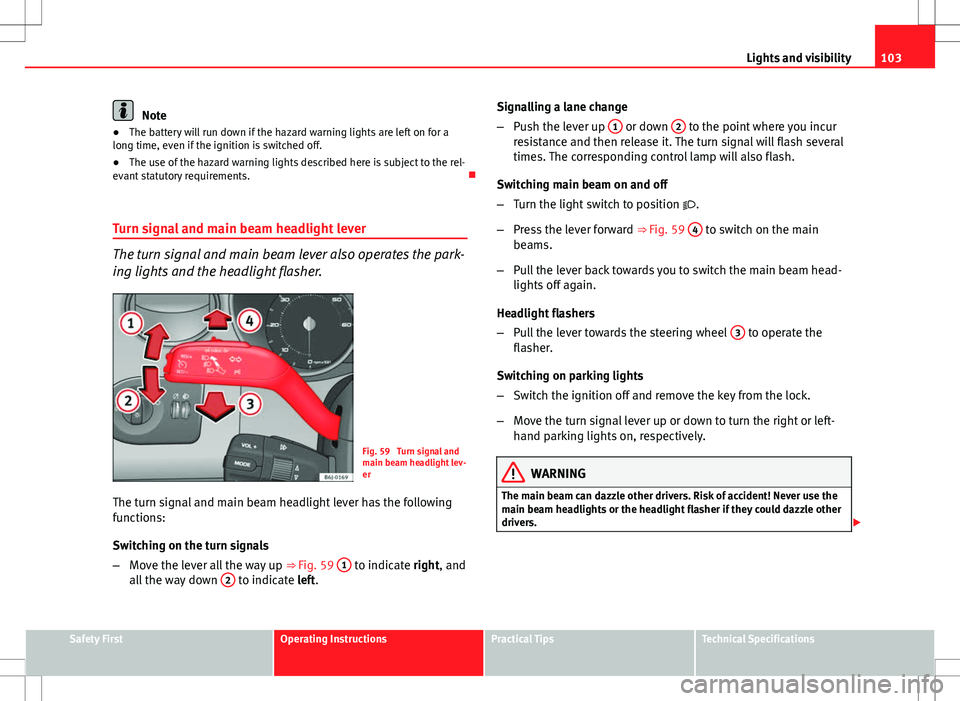
Fig. 59 Turn signal and
main beam headlight lev-
er
The turn signal and main beam headlight lever has the following
functions:
Switching on the turn signals
– Move the lever all the way up ⇒
Fig. 59 1
to indicate right, and
all the way down 2 to indicate left. Signalling a lane change
–
Push the lever up 1
or down 2 to the point where you incur
resistance and then release it. The turn signal will flash several
times. The corresponding control lamp will also flash.
Switching main beam on and off
– Turn the light switch to position .
– Press the lever forward ⇒ Fig. 59 4
to switch on the main
beams.
– Pull the lever back towards you to switch the main beam head-
lights off again.
Headlight flashers
– Pull the lever towards the steering wheel 3
to operate the
flasher.
Switching on parking lights
– Switch the ignition off and remove the key from the lock.
– Move the turn signal lever up or down to turn the right or left-
hand parking lights on, respectively.
WARNING
The main beam can dazzle other drivers. Risk of accident! Never use the
main beam headlights or the headlight flasher if they could dazzle other
drivers.
Safety FirstOperating InstructionsPractical TipsTechnical Specifications
Page 106 of 280
104Lights and visibility
Note
● The turn signals only work when the ignition is switched on. The corre-
sponding warning lamp or flashes in the instrument panel. The control
lamp flashes when the turn signals are operated, provided a trailer is
correctly attached and connected to the vehicle. If a turn signal bulb is de-
fective, the control lamp flashes at double speed. If the trailer turn signal
bulbs are damaged, control lamp does not light up. Change the bulb.
● The main beam headlights can only be switched on if the dipped beam
headlights are already on. The warning lamp then comes on in the instru-
ment panel.
● The headlight flasher comes on for as long as you pull the lever – even if
no other lights are switched on. The warning lamp then comes on in the
instrument panel.
● When the parking lights are switched on, the headlight and the tail light
on the corresponding side of the vehicle light up. The parking lights will on-
ly work if the key is removed from the ignition. If the lights are switched on,
an audible warning will be emitted while the driver door is open.
● If the turn signal lever is left on after the key has been taken out of the
ignition lock, an acoustic signal sounds when the driver door is opened.
This is a reminder to switch off the turn signal, unless of course you wish to
leave the parking light on. Interior lights
Front interior light
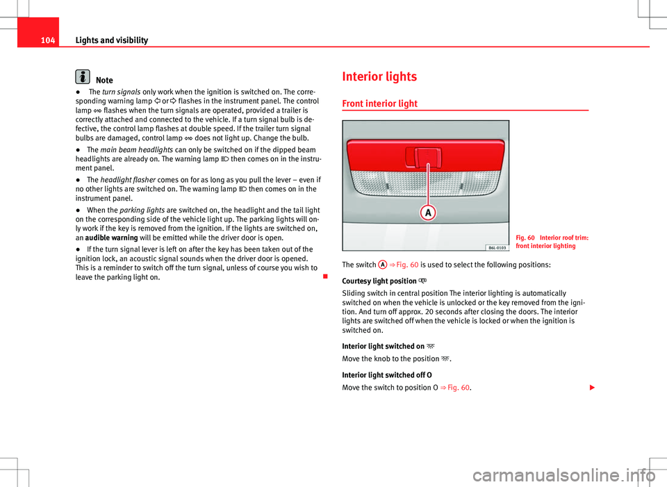
Fig. 60 Interior roof trim:
front interior lighting
The switch A
⇒ Fig. 60 is used to select the following positions:
Courtesy light position
Sliding switch in central position The interior lighting is automatically
switched on when the vehicle is unlocked or the key removed from the igni-
tion. And turn off approx. 20 seconds after closing the doors. The interior
lights are switched off when the vehicle is locked or when the ignition is
switched on.
Interior light switched on
Move the knob to the position .
Interior light switched off O
Move the switch to position O ⇒ Fig. 60.
Page 107 of 280
105
Lights and visibility
Note
If not all the vehicle doors are closed, the interior lights will be switched off
after approx. 10 minutes, providing the ignition key has been removed and
the courtesy light position selected. This prevents the battery from dis-
charging.
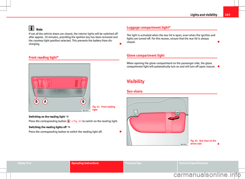
Front reading light*
Fig. 61 Front reading
light
Switching on the reading light
Press the corresponding button B
⇒ Fig. 61 to switch on the reading light.
Switching the reading lights off
Press the corresponding button to switch the reading light off. Luggage compartment light*
The light is activated when the rear lid is open, even when the ignition and
lights are turned off. For this reason, ensure that the rear lid is always
closed.
Glove compartment light
When opening the glove compartment on the passenger side, the glove
compartment light will automatically turn on and will turn off upon closure.
Visibility Sun visors
Fig. 62 Sun visor on the
driver side
Safety FirstOperating InstructionsPractical TipsTechnical Specifications
Page 109 of 280
107
Lights and visibility
WARNING
● Worn and dirty wiper blades reduce visibility and safety levels while
driving.
● In cold conditions, you should not use the wash/wipe system unless
you have warmed the windscreen with the heating and ventilation sys-
tem. The windscreen washer fluid could otherwise freeze on the wind-
screen and obscure your view of the road.
● Always note the corresponding warnings on ⇒ page 203.
CAUTION
In icy conditions, always check that the wiper blades are not frozen to the
glass before using the wipers for the first time. If you switch on the wind-
screen wipers when the wiper blades are frozen to the windscreen, you
could damage both the wiper blades and the wiper motor.
Note
● The windscreen wipers will only work when the ignition is switched on.
● The heat output of the heated jets* is controlled automatically when the
ignition is switched on, depending upon the outside temperature.
● In certain versions of vehicles with alarms, the windscreen wiper will on-
ly work in interval/rain sensor mode when the ignition is on and the bonnet
closed.
● When the interval wipe function is on, the intervals are directly propor-
tional to the speed. This way, the higher the vehicle speed the shorter the
intervals.
● If you stop the vehicle with the windscreen wiper in position 1 or 2, it
will automatically change to a lower speed. The set speed will be resumed
when the vehicle pulls away.
● The windscreen will be wiped again after approximately five seconds
once the “automatic wipe/wash system” has been operated, provided the
vehicle is in transit (drip function). If you activate the wipers less than three seconds after the drip function, a new wash sequence will begin without the
last wipe. For the “drip” function to work again, you have to turn the ignition
off and then on again.
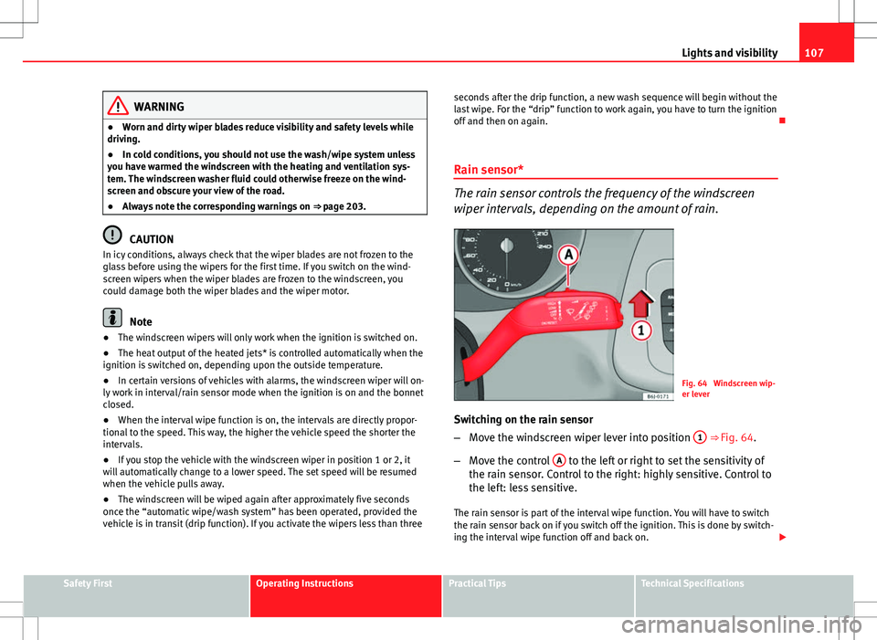
Rain sensor*
The rain sensor controls the frequency of the windscreen
wiper intervals, depending on the amount of rain.
Fig. 64 Windscreen wip-
er lever
Switching on the rain sensor
– Move the windscreen wiper lever into position 1
⇒ Fig. 64.
– Move the control A
to the left or right to set the sensitivity of
the rain sensor. Control to the right: highly sensitive. Control to
the left: less sensitive.
The rain sensor is part of the interval wipe function. You will have to switch
the rain sensor back on if you switch off the ignition. This is done by switch-
ing the interval wipe function off and back on.
Safety FirstOperating InstructionsPractical TipsTechnical Specifications