battery Seat Ibiza SC 2012 Owner's manual
[x] Cancel search | Manufacturer: SEAT, Model Year: 2012, Model line: Ibiza SC, Model: Seat Ibiza SC 2012Pages: 280, PDF Size: 3.67 MB
Page 6 of 280
Accessories, replacement of parts and
modifications . . . . . . . . . . . . . . . . . . . . . . . . . . . . . 183
Accessories and spare parts . . . . . . . . . . . . . . . . 183
Technical modifications . . . . . . . . . . . . . . . . . . . . 183
Roof aerial* . . . . . . . . . . . . . . . . . . . . . . . . . . . . . . 184
Mobile telephones and two-way radios . . . . . . . . 184
Fitting a towing bracket* . . . . . . . . . . . . . . . . . . . 185
Checking and refilling levels . . . . . . . . . . . . . . . 187
Refuelling . . . . . . . . . . . . . . . . . . . . . . . . . . . . . . . 187
LPG system* . . . . . . . . . . . . . . . . . . . . . . . . . . . . . 189
Petrol . . . . . . . . . . . . . . . . . . . . . . . . . . . . . . . . . . . 192
Diesel . . . . . . . . . . . . . . . . . . . . . . . . . . . . . . . . . . . 192
Working in the engine compartment . . . . . . . . . . 193
Engine oil . . . . . . . . . . . . . . . . . . . . . . . . . . . . . . . . 196
Coolant . . . . . . . . . . . . . . . . . . . . . . . . . . . . . . . . . 200
Washer fluid and windscreen wiper blades . . . . 202
Brake fluid . . . . . . . . . . . . . . . . . . . . . . . . . . . . . . . 206
Vehicle battery . . . . . . . . . . . . . . . . . . . . . . . . . . . 207
Wheels . . . . . . . . . . . . . . . . . . . . . . . . . . . . . . . . . . 209
If and when . . . . . . . . . . . . . . . . . . . . . . . . . . . . . . . 216
Vehicle tools, spare wheel . . . . . . . . . . . . . . . . . . 216
Wheel change . . . . . . . . . . . . . . . . . . . . . . . . . . . . 217
Tyre repair kit (Tyre-Mobility-System)* . . . . . . . . . 222
Fuses . . . . . . . . . . . . . . . . . . . . . . . . . . . . . . . . . . . 224
Bulb change . . . . . . . . . . . . . . . . . . . . . . . . . . . . . 227
Single headlight bulb change . . . . . . . . . . . . . . . 229
Double headlight bulb change . . . . . . . . . . . . . . . 231
Changing the bulbs of AFS headlights . . . . . . . . 235
Changing the fog light bulbs . . . . . . . . . . . . . . . . 236
Changing the rear, side and interior light bulbs . 237
Jump-starting . . . . . . . . . . . . . . . . . . . . . . . . . . . . . 241
Towing and tow-starting . . . . . . . . . . . . . . . . . . . . 244 Technical Specifications
. . . . . . . . . . . 247
Description of specifications . . . . . . . . . . . . . . . 247
Important information . . . . . . . . . . . . . . . . . . . . . 247
Information on fuel consumption . . . . . . . . . . . . 249
Towing a trailer . . . . . . . . . . . . . . . . . . . . . . . . . . . 249
Wheels . . . . . . . . . . . . . . . . . . . . . . . . . . . . . . . . . . 250
Technical specifications . . . . . . . . . . . . . . . . . . . . 251
Checking fluid levels . . . . . . . . . . . . . . . . . . . . . . . 251
Petrol engine 1.2 44 kW (60 PS) . . . . . . . . . . . . . 252
Petrol engine 1.2 51 kW (70 PS) . . . . . . . . . . . . . 253
Petrol engine 1.2 TSI 63 kW (85 PS) . . . . . . . . . . 254
Petrol engine/LPG 1.6 60 kW (81 PS) . . . . . . . . . 255
Petrol engine 1.4 63 kW (85 PS) . . . . . . . . . . . . . 256
Petrol engine 1.2 TSI 77 kW (105 PS) . . . . . . . . . 257
Petrol engine 1.2 TSI 77 kW (105 PS) Start-Stop 258
Petrol engine 1.6 77 kW (105 PS) . . . . . . . . . . . . 259
Petrol engine 1.4 110 kW (150 PS) . . . . . . . . . . . 260
Petrol engine 1.4 132 kW (180 PS) - Cupra . . . . . 261
Diesel engine 1.2 TDI CR 55 kW (75 PS) DPF
Start-Stop Ecomotive . . . . . . . . . . . . . . . . . . . . . . 262
Diesel engine 1.2 TDI CR 55 kW (75 PS) DPF . . . . 263
Diesel engine 1.6 TDI CR 66 kW (90 PS) DPF . . . . 264
Diesel engine 1.6 TDI CR 77 kW (105 PS) with/
without DPF . . . . . . . . . . . . . . . . . . . . . . . . . . . . . . 265
Diesel engine 2.0 TDI CR 105 kW (143 PS) DPF . 266
Dimensions and capacities . . . . . . . . . . . . . . . . . 267
Index . . . . . . . . . . . . . . . . . . . . . . . . . . . . . . . . . . . 269
4Table of Contents
Page 64 of 280
62Cockpit
The service interval display only indicates the dates of services that include
engine oil change. The dates of all other services, such as Inspection Serv-
ice or brake fluid change, appear in the sticker on the door pillar or in the
Maintenance Programme.
Vehicles with service intervals dependent on time/distance travelled al-
ready have certain service intervals set.
The intervals are calculated separately in vehicles with LongLife service.
Technical progress has made it possible to considerably reduce servicing re-
quirements. With the LongLife System, SEAT ensures that your vehicle only
has an interval service when it is necessary. To calculate this (max. two
years), the conditions under which the vehicle is used and the individual
driving style are also taken into account. The service pre-warning will ap-
pear at 20 days or less prior to the corresponding service. The distance trav-
elled is rounded off to the nearest 100 km (miles) and the time to full days.
The current service message can only be consulted 500 km (miles) or more
after the last service. Until that time, only dashes are displayed.
Service warning
A service warning will appear when the ignition is switched on if a service is
due soon.
The instrument panel display will show the “spanner symbol” and the
“km (miles)” indication, along with a clock symbol with the days remaining
until the date of the next service. The figure indicated is the maximum num-
ber of kilometres (miles) remaining before the date of the next service. The
indication changes after a few seconds. A “clock symbol” appears and the
number of days until the service appointment should be carried out.
Service
If a service is due, an audible warning will sound and the flashing “span-
ner” symbol will be shown along with the fixed text SERVICE.
If no service is carried out following the indication on the instrument panel,
the excess distance travelled and the excess time following the SERVICE
warning will be displayed. Reading the service message
The current service message
can be consulted with the ignition on, the en-
gine switched off and the vehicle at a standstill:
● Press the
button on the instrument panel as often as necessary until
the spanner symbol is displayed.
An overdue service is indicated by a minus sign in front of the mileage or
day information.
Resetting service interval display
If the service was not performed by a SEAT dealership, the display must be
reset as follows:
● Switch the ignition off.
● Press and hold the 0.0 / SET
button.
● Switch ignition back on.
● Release the 0.0 / SET
button and press the button within 20 seconds.
Do not reset the display between service intervals, as the display will other-
wise be incorrect.
If the display is reset manually, the next service interval will be indicated af-
ter 15 000 km (10 000 miles) or one year and will not be calculated individ-
ually.
Note
In LongLife Service vehicles, if the battery is disconnected for a long period,
the days remaining until the next service cannot be calculated. Therefore,
the service message indications may be incorrect. In this case, bear in mind
the maximum service intervals permitted in the ⇒ Booklet Maintenance Pro-
gramme.
Page 69 of 280
67
Cockpit
If several priority 1 faults are detected at the same time, the symbols will be
displayed one after the other for about 2 seconds at a time and will contin-
ue until the fault is corrected.
No menus will be shown in the display for the duration of a priority 1 warn-
ing message.
Examples of priority 1 warning messages (red)
● Brake system symbol with the warning message STOP BRAKE FLUID
INSTRUCTION MANUAL or STOP BRAKE FAULT INSTRUCTION MANUAL .
● Coolant symbol with the warning message STOP SEE COOLANT IN-
STRUCTION MANUAL.
● Engine oil pressure symbol with the warning message STOP ENGINE
OIL PRESSURE LOW! INSTRUCTION MANUAL .
Warning messages, Priority 2 (yellow)
If one of these faults occurs, the warning lamp lights up, and is accompa-
nied by one audible warning. Check the corresponding function as soon as
possible although the vehicle may be used without risk.
If several priority 2 warning messages are detected at the same time, the
symbols are displayed one after the other for about 2 seconds at a time. Af-
ter a set time, the information text will disappear and the symbol will be
shown as a reminder at the side of the display.
Priority 2 warning messages will not be shown until all Priority 1 warning
messages have been dealt with!
Examples of priority 2 warning messages (yellow): 1)
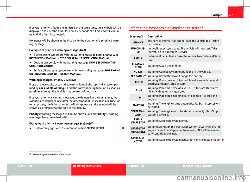
● Fuel warning light with the information text PLEASE REFUEL. Information messages displayed on the screen*
Message
a)Description
SERVICEThe service interval has ended. Take the vehicle to a Techni-
cal Service.
IMMOBILIS-
ERImmobiliser system active. The vehicle will not start. Take
the vehicle to a Technical Service.
ERRORInstrument panel faulty. Take the vehicle to a Technical Serv-
ice.
CLEAN AIRFILTERWarning: Clean the air filter.
NO KEYWarning: Correct key cannot be found in the vehicle.KEY BATTERYWarning: Key battery low. Change the battery.
CLUTCHWarning: Press the clutch to start. In vehicles with manual
gearbox and Start/Stop system.
--> P/NWarning: Place the selector level in P/N to start. Only in ve-
hicles with automatic gearbox.
--> PWarning: Place the selector lever in position P to stop the
engine.
STARTINGWarning: The engine starts automatically. Start-Stop system
activated.
START MAN- UALLYWarning: The engine must be started manually. Start-Stop
system activated.
ERROR
START STOPWarning: Start-Stop system error.
START-STOP
IMPOSSIBLEWarning: Although the Start-Stop system is switched on, the
engine cannot be stopped automatically. Not all the neces-
sary conditions are met.
START-STOP ACTIVEWarning: Start-Stop system activated. Vehicle in Stop mode.
1)
Depending on the version of the model.
Safety FirstOperating InstructionsPractical TipsTechnical Specifications
Page 74 of 280
72Cockpit
Tyre pressure*
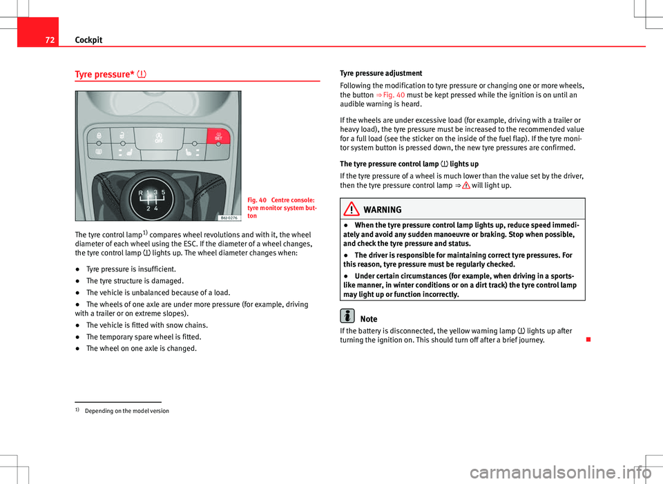
Fig. 40 Centre console:
tyre monitor system but-
ton
The tyre control lamp 1)
compares wheel revolutions and with it, the wheel
diameter of each wheel using the ESC. If the diameter of a wheel changes,
the tyre control lamp lights up. The wheel diameter changes when:
● Tyre pressure is insufficient.
● The tyre structure is damaged.
● The vehicle is unbalanced because of a load.
● The wheels of one axle are under more pressure (for example, driving
with a trailer or on extreme slopes).
● The vehicle is fitted with snow chains.
● The temporary spare wheel is fitted.
● The wheel on one axle is changed. Tyre pressure adjustment
Following the modification to tyre pressure or changing one or more wheels,
the button ⇒ Fig. 40 must be kept pressed while the ignition is on until an
audible warning is heard.
If the wheels are under excessive load (for example, driving with a trailer or
heavy load), the tyre pressure must be increased to the recommended value
for a full load (see the sticker on the inside of the fuel flap). If the tyre moni-
tor system button is pressed down, the new tyre pressures are confirmed.
The tyre pressure control lamp
lights up
If the tyre pressure of a wheel is much lower than the value set by the driver,
then the tyre pressure control lamp ⇒
will light up.
WARNING
● When the tyre pressure control lamp lights up, reduce speed immedi-
ately and avoid any sudden manoeuvre or braking. Stop when possible,
and check the tyre pressure and status.
● The driver is responsible for maintaining correct tyre pressures. For
this reason, tyre pressure must be regularly checked.
● Under certain circumstances (for example, when driving in a sports-
like manner, in winter conditions or on a dirt track) the tyre control lamp
may light up or function incorrectly.
Note
If the battery is disconnected, the yellow warning lamp lights up after
turning the ignition on. This should turn off after a brief journey.
1)
Depending on the model version
Page 76 of 280
74Cockpit
Emission control system*
This warning lamp monitors the exhaust system.
Control lamp flashes:
When there is misfiring that can damage the catalytic converter. Reduce
speed and drive carefully to the nearest specialised workshop to have the
engine checked.
Control lamp is lit:
If a fault has developed during driving which has reduced the quality of the
exhaust gas (e.g. lambda probe fault). Reduce speed and drive carefully to
the nearest specialised workshop to have the engine checked.
Coolant level* / temperature
The warning lamp lights up if the coolant temperature is too
high or if the coolant level is too low.
There is a fault if:
● The warning symbol does not go out again after a few seconds.
● The warning lamp lights up or flashes while the vehicle is moving, and
three acoustic warning signals ⇒
are emitted.
This means that either the coolant level is too low or the coolant tempera-
ture is too high.
Coolant temperature too high
If the warning light comes on, stop the vehicle, switch off the engine and
wait for it to cool down. Check the coolant level.
If the coolant level is correct, the overheating may be caused by a malfunc-
tion of the radiator fan. Check the radiator fan fuse and have it replaced if
necessary ⇒ page 224. If the control lamp lights up again after driving on for a short distance,
stop
the vehicle and switch the engine off . Contact a Technical Service or a spe-
cialised workshop.
Coolant level too low
If the warning light comes on, stop the vehicle, switch off the engine and
wait for it to cool down First check the coolant level. If the level of the cool-
ant is below the “MIN” mark, top up with coolant liquid ⇒
.
WARNING
● If your vehicle is immobilised for technical reasons, move it to a safe
distance from traffic. Turn the engine off, turn the hazard lights on and
place the warning triangle.
● Never open the bonnet if you can see or hear steam or coolant escap-
ing from the engine compartment. Risk of scalding. Wait until you can no
longer see or hear escaping steam or coolant.
● The engine compartment is a dangerous area! Before carrying out any
work in the engine compartment, switch off the engine and allow it to
cool down. Always note the corresponding warnings ⇒ page 193.
Alternator
This warning lamp signals a fault in the alternator.
The warning lamp lights up when the ignition is switched on. It should
go out when the engine has started running.
If the warning lamp lights up while driving, the alternator is no longer
charging the battery. You should immediately drive to the nearest special-
ised workshop.
You should avoid using electrical equipment that is not absolutely necessa-
ry because this will drain the battery.
Page 87 of 280
85
Opening and closing
Radio frequency remote control*
Locking and unlocking the vehicle
The radio frequency remote control key is used to lock and
unlock the vehicle from a distance.
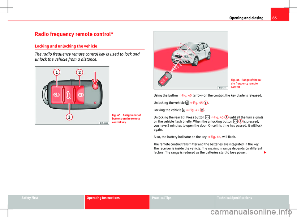
Fig. 45 Assignment of
buttons on the remote
control key
Fig. 46 Range of the ra-
dio frequency remote
control
Using the button ⇒ Fig. 45 (arrow) on the control, the key blade is released.
Unlocking the vehicle
⇒ Fig. 45 1.
Locking the vehicle
⇒ Fig. 45 2.
Unlocking the rear lid. Press button
⇒ Fig. 45 3 until all the turn signals
on the vehicle flash briefly. When the unlocking button
3 is pressed,
you have 2 minutes to open the door. Once this time has passed, it will lock
again.
Also, the battery indicator on the key ⇒ Fig. 46, will flash.
The remote control transmitter and the batteries are integrated in the key.
The receiver is inside the vehicle. The maximum range depends on different
factors. The range is reduced as the batteries start to lose power.
Safety FirstOperating InstructionsPractical TipsTechnical Specifications
Page 88 of 280
86Opening and closing
WARNING
● An improper use of the key can cause serious injuries.
● Never leave children or disabled persons in the vehicle. In case of
emergency, they may not be able to leave the vehicle or manage on their
own.
● Never forget the keys inside the vehicle. Otherwise, this could result
in serious injuries, accidents or even the theft of your vehicle. Always
take the key with you when you leave the vehicle.
● An uncontrolled use of the key could start the engine or activate any
electric equipment (e.g. electric windows), causing risk of accident. The
vehicle can be locked when using the remote control key. This could com-
plicate the aid in case of emergency.
Note
● The radio frequency remote control key functions only when you are
within range ⇒ Fig. 46.
● If the vehicle cannot be unlocked or locked by using the radio frequency
remote control, the remote control key will have to be re-synchronised. For
this, go to your Technical Service.
Changing the battery
If the battery indicator does not flash when the buttons are pushed, the bat-
tery must be replaced.
CAUTION
The use of inappropriate batteries may damage the radio frequency remote
control. For this reason, always replace the dead battery with another of the
same size and power.
For the sake of the environment
Used batteries must be disposed of at an appropriate waste facility or
through an authorised service, given that their components can affect the
environment.
Synchronising the remote control key
If it is not possible to unlock or lock the door with the remote
control, it should be re-synchronised.
While the vehicle is open:
– Press the
button
2 ⇒
Fig. 45 on the remote control.
– Then close the vehicle using the key bit within one minute.
While the vehicle is closed:
– Press the
button
1 ⇒ Fig. 45 on the remote control.
– Then close the vehicle using the key bit within one minute.
It is possible that the vehicle could no longer be opened and closed with
the remote control if the button
is repeatedly pressed outside of the ef-
fective range of the radio frequency remote control. The remote control key
will have to be resynchronised.
Spare remote control keys are available in your Technical Service, where
they must be matched to the locking system.
Up to five remote control keys can be used.
Page 89 of 280
87
Opening and closing
Anti-theft alarm system* Description of anti-theft alarm system*
The anti-theft alarm triggers if unauthorised movements are
detected around the vehicle.
The anti-theft alarm makes it more difficult to break into the vehicle or steal
it. The system will initiate acoustic and optical warning signals when your
vehicle is tried to be forced.
The anti-theft alarm system is automatically switched on when locking the
vehicle. For this, either rotate the key in the locking position or press button
2 on the radio frequency remote control*. The system is immediately ac-
tivated and the turn signal light located on the driver door will flash along
with the turn signals, indicating that the alarm and the locking security sys-
tem (double lock) have been turned on.
If any of the doors or the bonnet are open, they will not be included in the
protection zones of the vehicle when the alarm is connected. If the door or
the bonnet are subsequently closed, they will be automatically included in
the protection areas of the vehicle and the turn signals will flash according-
ly when the doors close.
● The turn signal light will flash twice on opening and deactivating the
alarm.
● The turn signal light will flash once on closing and activating the alarm.
When does the system trigger an alarm?
The system triggers an alarm if the following unauthorised actions are car-
ried out when the vehicle is locked: ●
Opening of vehicle with mechanical key without switching ignition on
within the next 15 seconds
● Opening a door
● Opening the bonnet
● Opening the rear lid
● Ignition switched on with a non-validated key.
● Movements in the driving compartment (vehicles with a volume sensor)
● Towing of the vehicle 1)
● Tilt angle (tow-away protection) 1)
● Undue manipulation of the alarm
● Battery handling
The acoustic signals sound and the turn signals flash for approx. 30 sec-
onds. This may be repeated up to 10 times depending on the country.
Opening all the doors in manual mode
In vehicles without alarm, when opening the driver door manually all the
doors are opened.
How to switch the alarm off
To deactivate the anti-theft alarm, turn the key to the opening direction,
open the door and switch the ignition on, or press the unlocking button
on the remote control.
In vehicles equipped with an anti-theft alarm system, you have 15 seconds
to insert the key in the ignition lock and activate the ignition if the vehicle is
opened using the driver door key.
Otherwise, the alarm will trigger for 30 sec. and the ignition will be blocked.
1)
With vehicles fitted with a tow-away protection
Safety FirstOperating InstructionsPractical TipsTechnical Specifications
Page 93 of 280
91
Opening and closing
WARNING
● Always close the rear lid properly. Risk of accident or injury.
● The rear lid must not be opened when the reverse or rear fog lights
are lit. This may damage the tail lights
● Do not close the rear lid by pushing it down with your hand on the
rear window. The glass could smash. Risk of injury!
● Ensure the rear lid is locked after closing it. If not, it may open unex-
pectedly while driving.
● Never allow children to play in or around the vehicle. A locked vehicle
can be subjected to extremely high and low temperatures, depending on
the time of year, thus causing serious injuries/illness. It could even have
fatal consequences. Close and lock both the rear lid and all the other
doors when you are not using the vehicle.
● Closing the rear lid without observing and ensuring it is clear could
cause serious injury to you and to third parties. Make sure that no one is
in the path of the rear lid.
● Never drive with the rear lid open or half-closed, exhaust gases may
penetrate into the interior of the vehicle. Danger of poisoning!
● If you only open the rear lid, do not leave the key inside. The vehicle
will not be opened if the key is left inside.
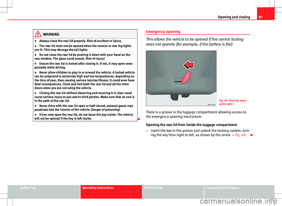
Emergency opening
This allows the vehicle to be opened if the central locking
does not operate (for example, if the battery is flat)
Fig. 49 Rear lid: emer-
gency open
There is a groove in the luggage compartment allowing access to
the emergency opening mechanism.
Opening the rear lid from inside the luggage compartment
– Insert the key in the groove and unlock the locking system, turn-
ing the key from right to left, as shown by the arrow ⇒ Fig. 49.
Safety FirstOperating InstructionsPractical TipsTechnical Specifications
Page 104 of 280
102Lights and visibility
For the sake of the environment
The heated rear window should be switched off as soon as the glass is dem-
isted. By saving electrical power you can also save fuel.
Note
To avoid possible damage to the battery, an automatic temporary discon-
nection of this function is possible, coming back on when normal operating
conditions are re-established.
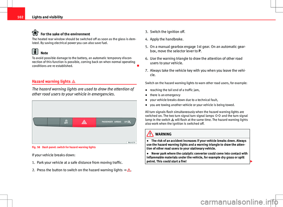
Hazard warning lights
The hazard warning lights are used to draw the attention of
other road users to your vehicle in emergencies.
Fig. 58 Dash panel: switch for hazard warning lights
If your vehicle breaks down:
1. Park your vehicle at a safe distance from moving traffic.
2. Press the button to switch on the hazard warning lights ⇒
.3. Switch the ignition off.
4. Apply the handbrake.
5. On a manual gearbox engage 1st gear. On an automatic gear-
box, move the selector lever to P.
6. Use the warning triangle to draw the attention of other road users to your vehicle.
7. Always take the vehicle key with you when you leave the vehi- cle.
Switch on the hazard warning lights to warn other road users, for example:
● reaching the tail end of a traffic jam,
● there is an emergency
● your vehicle breaks down due to a technical fault,
● you are towing another vehicle or your vehicle is being towed.
All turn signals flash simultaneously when the hazard warning lights are
switched on. The two turn signal turn signal lamps and the turn signal
lamp in the switch will flash at the same time. The hazard warning lights
also work when the ignition is switched off.
WARNING
● The risk of an accident increases if your vehicle breaks down. Always
use the hazard warning lights and a warning triangle to draw the atten-
tion of other road users to your stationary vehicle.
● Never park where the catalytic converter could come into contact with
inflammable materials under the vehicle, for example dry grass or spilt
petrol. This could start a fire!