service interval Seat Ibiza SC 2012 Owner's manual
[x] Cancel search | Manufacturer: SEAT, Model Year: 2012, Model line: Ibiza SC, Model: Seat Ibiza SC 2012Pages: 280, PDF Size: 3.67 MB
Page 58 of 280
56Cockpit
Rev counter
The rev counter displays the engine speed in revolutions per
minute.
The start of the red zone ⇒ Fig. 30 1
indicates the maximum engine speed
operating at service temperature. However, it is advisable to change up into
a higher gear, move the selector lever to D or lift your foot off the accelerator
before the needle reaches the red zone.
CAUTION
To prevent possible engine malfunctions, the rev counter needle should not
reach the red zone. The start of the red zone on the dial is different for some
engine versions.
For the sake of the environment
Changing up into higher gears sooner, following the recommended gear in-
dications ⇒ Fig. 33 will help you to reduce fuel consumption, emissions and
also engine noise.
Speedometer
The speedometer is equipped with a digital odometer and a trip recorder, in
addition to a service intervals display.
During the running-in period, the instructions shown on ⇒ page 167
should be followed. LPG system*
LPG gauge
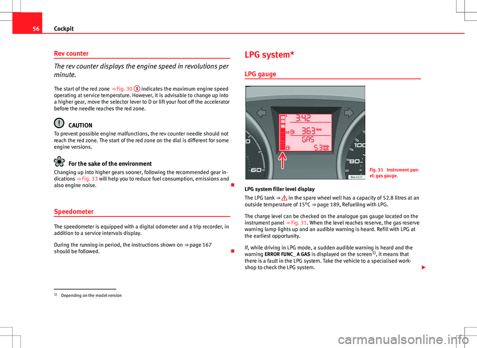
Fig. 31 Instrument pan-
el: gas gauge.
LPG system filler level display
The LPG tank ⇒
in the spare wheel well has a capacity of 52.8 litres at an
outside temperature of 15°C ⇒ page 189, Refuelling with LPG.
The charge level can be checked on the analogue gas gauge located on the
instrument panel ⇒ Fig. 31. When the level reaches reserve, the gas reserve
warning lamp lights up and an audible warning is heard. Refill with LPG at
the earliest opportunity.
If, while driving in LPG mode, a sudden audible warning is heard and the
warning ERROR FUNC_ A GAS is displayed on the screen 1)
, it means that
there is a fault in the LPG system. Take the vehicle to a specialised work-
shop to check the LPG system.
1)
Depending on the model version
Page 63 of 280
61
Cockpit
This may be deactivated by pressing the RESET
button. The speed may be
altered using the rocker switch B in steps of 5 km/h (mph) within 5 sec-
onds of the initial memory value.
WARNING
There could be black ice on the road surface even if the “snowflake sym-
bol” is not shown. For this reason you should not rely exclusively on this
display - Risk of accident!
Note
When the vehicle is stationary or travelling at very low speeds, the tempera-
ture displayed may be slightly higher than the actual outside temperature
as a result of the heat radiated from the engine.
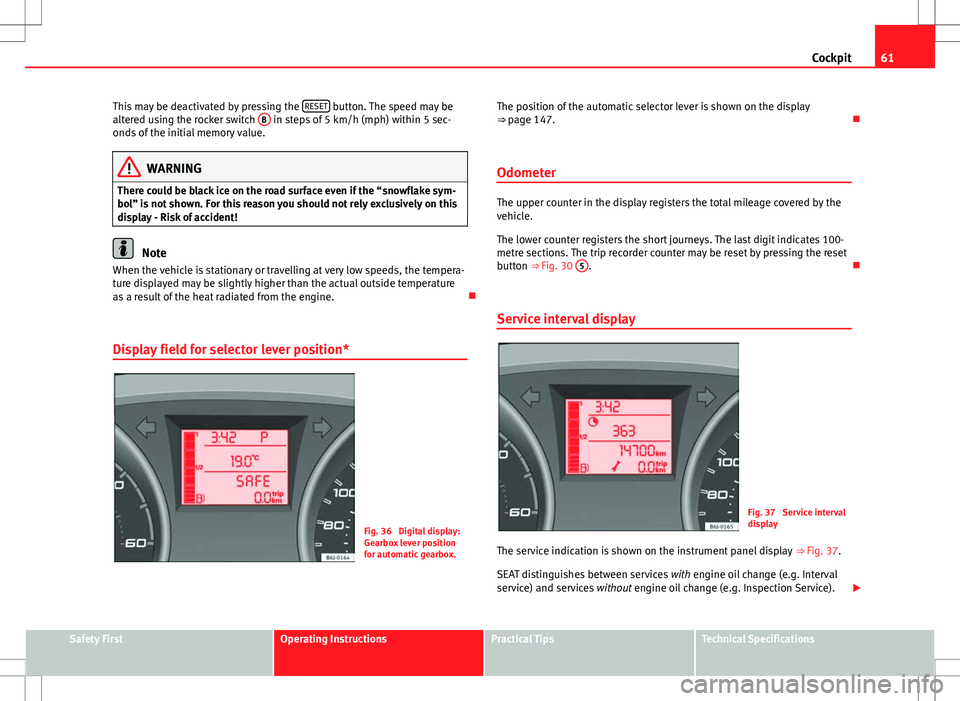
Display field for selector lever position*
Fig. 36 Digital display:
Gearbox lever position
for automatic gearbox. The position of the automatic selector lever is shown on the display
⇒ page 147.
Odometer
The upper counter in the display registers the total mileage covered by the
vehicle.
The lower counter registers the short journeys. The last digit indicates 100-
metre sections. The trip recorder counter may be reset by pressing the reset
button ⇒ Fig. 30 5
.
Service interval display
Fig. 37 Service interval
display
The service indication is shown on the instrument panel display ⇒ Fig. 37.
SEAT distinguishes between services with engine oil change (e.g. Interval
service) and services without engine oil change (e.g. Inspection Service).
Safety FirstOperating InstructionsPractical TipsTechnical Specifications
Page 64 of 280
62Cockpit
The service interval display only indicates the dates of services that include
engine oil change. The dates of all other services, such as Inspection Serv-
ice or brake fluid change, appear in the sticker on the door pillar or in the
Maintenance Programme.
Vehicles with service intervals dependent on time/distance travelled al-
ready have certain service intervals set.
The intervals are calculated separately in vehicles with LongLife service.
Technical progress has made it possible to considerably reduce servicing re-
quirements. With the LongLife System, SEAT ensures that your vehicle only
has an interval service when it is necessary. To calculate this (max. two
years), the conditions under which the vehicle is used and the individual
driving style are also taken into account. The service pre-warning will ap-
pear at 20 days or less prior to the corresponding service. The distance trav-
elled is rounded off to the nearest 100 km (miles) and the time to full days.
The current service message can only be consulted 500 km (miles) or more
after the last service. Until that time, only dashes are displayed.
Service warning
A service warning will appear when the ignition is switched on if a service is
due soon.
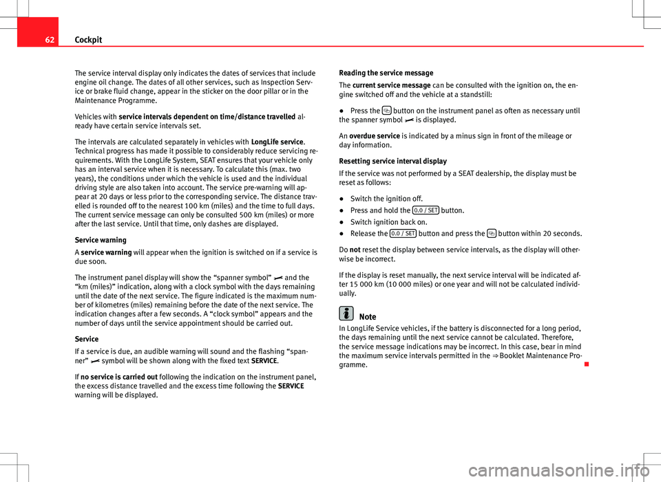
The instrument panel display will show the “spanner symbol” and the
“km (miles)” indication, along with a clock symbol with the days remaining
until the date of the next service. The figure indicated is the maximum num-
ber of kilometres (miles) remaining before the date of the next service. The
indication changes after a few seconds. A “clock symbol” appears and the
number of days until the service appointment should be carried out.
Service
If a service is due, an audible warning will sound and the flashing “span-
ner” symbol will be shown along with the fixed text SERVICE.
If no service is carried out following the indication on the instrument panel,
the excess distance travelled and the excess time following the SERVICE
warning will be displayed. Reading the service message
The current service message
can be consulted with the ignition on, the en-
gine switched off and the vehicle at a standstill:
● Press the
button on the instrument panel as often as necessary until
the spanner symbol is displayed.
An overdue service is indicated by a minus sign in front of the mileage or
day information.
Resetting service interval display
If the service was not performed by a SEAT dealership, the display must be
reset as follows:
● Switch the ignition off.
● Press and hold the 0.0 / SET
button.
● Switch ignition back on.
● Release the 0.0 / SET
button and press the button within 20 seconds.
Do not reset the display between service intervals, as the display will other-
wise be incorrect.
If the display is reset manually, the next service interval will be indicated af-
ter 15 000 km (10 000 miles) or one year and will not be calculated individ-
ually.
Note
In LongLife Service vehicles, if the battery is disconnected for a long period,
the days remaining until the next service cannot be calculated. Therefore,
the service message indications may be incorrect. In this case, bear in mind
the maximum service intervals permitted in the ⇒ Booklet Maintenance Pro-
gramme.
Page 69 of 280
67
Cockpit
If several priority 1 faults are detected at the same time, the symbols will be
displayed one after the other for about 2 seconds at a time and will contin-
ue until the fault is corrected.
No menus will be shown in the display for the duration of a priority 1 warn-
ing message.
Examples of priority 1 warning messages (red)
● Brake system symbol with the warning message STOP BRAKE FLUID
INSTRUCTION MANUAL or STOP BRAKE FAULT INSTRUCTION MANUAL .
● Coolant symbol with the warning message STOP SEE COOLANT IN-
STRUCTION MANUAL.
● Engine oil pressure symbol with the warning message STOP ENGINE
OIL PRESSURE LOW! INSTRUCTION MANUAL .
Warning messages, Priority 2 (yellow)
If one of these faults occurs, the warning lamp lights up, and is accompa-
nied by one audible warning. Check the corresponding function as soon as
possible although the vehicle may be used without risk.
If several priority 2 warning messages are detected at the same time, the
symbols are displayed one after the other for about 2 seconds at a time. Af-
ter a set time, the information text will disappear and the symbol will be
shown as a reminder at the side of the display.
Priority 2 warning messages will not be shown until all Priority 1 warning
messages have been dealt with!
Examples of priority 2 warning messages (yellow): 1)
● Fuel warning light with the information text PLEASE REFUEL. Information messages displayed on the screen*
Message
a)Description
SERVICEThe service interval has ended. Take the vehicle to a Techni-
cal Service.
IMMOBILIS-
ERImmobiliser system active. The vehicle will not start. Take
the vehicle to a Technical Service.
ERRORInstrument panel faulty. Take the vehicle to a Technical Serv-
ice.
CLEAN AIRFILTERWarning: Clean the air filter.
NO KEYWarning: Correct key cannot be found in the vehicle.KEY BATTERYWarning: Key battery low. Change the battery.
CLUTCHWarning: Press the clutch to start. In vehicles with manual
gearbox and Start/Stop system.
--> P/NWarning: Place the selector level in P/N to start. Only in ve-
hicles with automatic gearbox.
--> PWarning: Place the selector lever in position P to stop the
engine.
STARTINGWarning: The engine starts automatically. Start-Stop system
activated.
START MAN- UALLYWarning: The engine must be started manually. Start-Stop
system activated.
ERROR
START STOPWarning: Start-Stop system error.
START-STOP
IMPOSSIBLEWarning: Although the Start-Stop system is switched on, the
engine cannot be stopped automatically. Not all the neces-
sary conditions are met.
START-STOP ACTIVEWarning: Start-Stop system activated. Vehicle in Stop mode.
1)
Depending on the version of the model.
Safety FirstOperating InstructionsPractical TipsTechnical Specifications
Page 128 of 280
126Seats and storage compartments
CAUTION
● Before closing the rear lid, ensure that the rear shelf is correctly fitted.
● An overloaded luggage compartment could mean that the rear shelf is
not correctly seated and it may be bent or damaged.
● If the luggage compartment is overloaded, remove the tray.
Note
● Ensure that, when placing items of clothing on the luggage compart-
ment cover, rear visibility is not reduced.
Roof rack*
Please observe the following points if you intend to carry loads on the roof:
● For safety reasons, only luggage racks and accessories supplied by SEAT
Official Services should be used.
● It is essential that you follow the assembly instructions included with
the bars exactly, being especially careful to position front and rear luggage
compartment cover bars on the special housings on the longitudinal bars.
You must also respect their position according to the direction of travel indi-
cated in the assembly manual. Not following these instructions may dam-
age the bodywork.
● Pay special attention to the tightening torque of the attachment bolts
and check them following a short journey. If necessary, retighten the bolts
and check them at regular intervals. ●
Distribute the load evenly. A maximum load of 40 kg only is permitted
for each roof rack system support bar, the load must be distributed evenly
along the entire length. However, the maximum load permitted for the en-
tire roof (including the support system) of 75 kg must not be exceeded nor
should the total weight of the vehicle be exceeded. See the Technical Data
section.
● When transporting heavy or large objects on the roof, any change in the
normal vehicle behaviour due to a change in the centre of gravity or an in-
creased wind resistance must be taken into account. For this reason, a suit-
able speed and driving style must be used.
● For those vehicles fitted with a sliding/tilting sunroof*, ensure that it
does not interfere with the load on the roof rack system when opened.
Page 137 of 280
135
Air conditioning
Air recirculation mode
Air recirculation mode prevents fumes or unpleasant smells
from coming from the outside. – Press the button
to switch air recirculation mode on or off.
This is ON if the symbol ⇒ Fig. 95 is displayed on the screen.
Air recirculation mode prevents strong odours in the ambient air from enter-
ing the vehicle interior, for example when passing through a tunnel or in a
traffic jam.
When the outside temperature is low, air recirculation mode improves heat-
ing performance by heating air from the interior instead of cold air from the
outside.
When the outside temperature is high, air recirculation mode improves cool-
ing performance by cooling air from the interior instead of warm air from
outside.
For safety reasons, the air recirculation should not be switched on when the
air distribution control is set to the windscreen setting .
WARNING
In air recirculation mode, no cold air from the outside enters the vehicle
interior. If the air conditioner is switched off, the windows can quickly
mist over. Therefore, never leave the air recirculation mode switched on
for a long time (risk of accident).
Note
When engaging reverse gear, the air recirculation is connected automatical-
ly to prevent the entrance of exhaust gases in the vehicle on travelling back-
wards. In this case the symbol
for air recirculation is not displayed. General notes
Pollution filter
The pollution filter (a combined particulate filter and active carbon filter)
serves as a barrier against impurities in the outside air, including dust and
pollen.
For the air conditioner to work with maximum efficiency, the pollution filter
must be replaced at the specified intervals in the Maintenance Programme.
If the filter loses efficiency prematurely due to use in areas reaching very
high pollution levels, the pollen filter must be changed more frequently
than stated in the Service Schedule.
CAUTION
● If you suspect that the air conditioner is damaged, switch it off with but-
ton AC
to prevent further damage and have it checked by a specialised
workshop.
● Repairs to the air conditioner require specialist knowledge and special
tools. Therefore, we recommend you to take the vehicle to a specialised
workshop.
Note
● If the humidity and temperature outside the vehicle are high, condensa-
tion can drip off the evaporator in the cooling system and so forming a pud-
dle underneath the vehicle. This is completely normal and there is no need
to suspect a leak.
● Keep the air intake slots in front of the windscreen free of snow, ice and
leaves to ensure heating and cooling are not impaired, and to prevent the
windows from misting over.
● The air from the vents flows through the vehicle interior and is extracted
by slots designed for this purpose. Therefore, do not cover these slots with
items of clothing or other objects.
Safety FirstOperating InstructionsPractical TipsTechnical Specifications
Page 175 of 280
173
Driving and the environment
Exterior mirrors
Check whether you can see enough of the road behind the trailer with the
standard rear vision mirrors. If this is not the case, you should have addi-
tional exterior mirrors fitted. Both exterior mirrors should be mounted on
hinged extension brackets. Adjust the mirrors to give sufficient vision to the
rear.
WARNING
Never transport people in a trailer. This could result in fatal accidents.
Note
● Towing a trailer places additional demands on the vehicle. We recom-
mend additional services between the normal inspection intervals if the ve-
hicle is used frequently for towing a trailer.
● Find out whether special regulations apply to towing a trailer in your
country.
Ball coupling of towing bracket*
The ball coupling is provided with instructions on fitting and removing the
ball coupling of the towing bracket.
WARNING
The towing bracket ball coupling must be stored securely in the luggage
compartment to prevent them being flung through the vehicle and caus-
ing injury.
Note
● By law, the ball coupling must be removed if a trailer is not being towed
if it obscures the number plate. Driving tips
Driving with a trailer always requires extra care.
Weight distribution
The weight distribution of a loaded trailer with an unladen vehicle is very
unfavourable. However, if this cannot be avoided, drive extra slowly to allow
for the unbalanced weight distribution.
Speed
The stability of the vehicle and trailer is reduced with increasing speed. For
this reason, it is advisable not to drive at the maximum permissible speed
in an unfavourable road, weather or wind conditions. This applies especially
when driving downhill.
You should always reduce speed immediately if the trailer shows the slight-
est sign of snaking. Never try to stop the “snaking” by increasing speed.
Always brake in due course. If the trailer has an overrun brake, apply the
brakes gently at first and then, firmly. This will prevent the jerking that can
be caused by locking of trailer wheels. Select a low gear in due course be-
fore going down a steep downhill. This enables you to use the engine brak-
ing to slow down the vehicle.
Reheating
At very high temperatures and during prolonged slopes, driving in a low
gear and high engine speed, always monitor the coolant temperature gauge
⇒ page 53.
Electronic Stability Control*
The ESC* system helps to stabilise the trailer in case of skidding or rocking.
Safety FirstOperating InstructionsPractical TipsTechnical Specifications
Page 198 of 280
196Checking and refilling levels
WARNING (Continued)
● Wait until no more steam, smoke or coolant is emitted from the bon-
net, then carefully open the bonnet.
● When working in the engine compartment, always observe the safety
warnings ⇒ page 193.
Closing the bonnet
– Slightly raise the bonnet
– Release the bonnet stay and replace it in its support.
– At a height of about 30 cm let it fall so it is locked.
If the bonnet does not close, do not press downwards. Open it once more
and let it fall as before.
WARNING
If the bonnet is not closed properly, it could open while you are driving
and completely obscure your view of the road. Risk of accident.
● After closing the bonnet, always check that it is properly secured. The
bonnet must be flush with the surrounding body panels.
● If you notice that the bonnet latch is not secured when the vehicle is
moving, stop the vehicle immediately and close the bonnet properly.
Risk of accident.
Engine oil
General notes
The engine comes with a special, multi-grade oil that can be used all year
round.
Because the use of high-quality oil is essential for the correct operation of
the engine and its long useful life, when topping up or changing oil, use on-
ly those oils that comply with VW standards.
The specifications (VW standards) set out in the following page should ap-
pear on the container of the service oil; when the container displays the
specific standards for petrol and diesel engines together, it means that the
oil can be used for both types of engines.
We recommend that the oil change, indicated in the Maintenance Pro-
gramme, be performed by a Technical Service or a specialised workshop.
The correct oil specifications for your engine are listed in ⇒ page 197, Oil
properties.
Service intervals
Service intervals can be flexible (LongLife service) or fixed (dependent on
time/distance travelled).
If the PR code that appears on the back of the “Maintenance Programme”
booklet is QG1, this means that your vehicle has the LongLife service pro-
grammed. If it has the codes QG0 or QG2 the interval service is dependent
on time/distance travelled.
Flexible service intervals (LongLife service intervals*)
Special oils and processes have been developed which, depending on the
characteristics and individual driving profiles, enable the extension of the
oil change service (LongLife service intervals).
Page 199 of 280
197
Checking and refilling levels
Because this oil is essential for extending the service intervals, it must only
be used observing the following indications:
● Avoid mixing it with oil for fixed service intervals.
● Only in exceptional circumstances, if the engine oil level is too low
⇒ page 198 and LongLife oil is not available, it is permitted to top up
(once) with oil for fixed service intervals ⇒ page 197 (up to a maximum of
0.5 litres).
Fixed service intervals*
If your vehicle does not have the “LongLife service interval” or it has been
disabled (by request), you may use oils for fixed service intervals, which al-
so appear in ⇒ page 197, Oil properties. In this case, your vehicle must be
serviced after a fixed interval of 1 year/15 000 km (10 000 miles)(whatever
comes first) ⇒ Booklet Maintenance Programme.
● In exceptional circumstances, if the engine oil level is too low
⇒ page 198 and you cannot obtain the oil specified for your vehicle, you
can put in a small quantity of oil conforming to the specification ACEA A2 or
ACEA A3 (petrol engines) or ACEA B3 or ACEA B4 (diesel engines) (up to 0.5
l).
Vehicles with diesel particulate filter*
The “Maintenance Programme” states whether your vehicle is fitted with a
diesel particulate filter.
Only VW 507 00 engine oil, with reduced ash formation, may be used in die-
sel engines equipped with particulate filter. Using other types of oil will
cause a higher soot concentration and reduce the life of the DPF. Therefore:
● Avoid mixing this oil with other engine oils.
● Only in exceptional circumstances, if the engine oil level is too low
⇒ page 198 and you cannot obtain the oil specified for your vehicle, you
can use a small quantity of oil (once) conforming to the VW 506 00,
VW 506 01, VW 505 00, VW 505 01 or ACEA B3 / ACEA B4 specification. (up
to 0.5 l). Oil properties
Engine typeSpecificationPetrol without flexible service in-
tervalVW 502 00/VW 504 00
Petrol with flexible service inter-
val (LongLife)VW 504 00
Diesel. Engines without Particu-
late filter (DPF)VW 505 01/VW 506 01/VW 507 00
Diesel. Particulate Filter Engines
(DPF).
With or without flexible service
interval (with and without Long-
life)
a)VW 507 00
a)
Only use recommended oils, otherwise you may damage the engine.
Engine oil additives
No type of additive should be mixed with the engine oil. The deterioration
caused by these additives is not covered by the warranty.
Note
Before a long trip, we recommend finding an engine oil that conforms to the
corresponding VW specifications and recommend keeping it in the vehicle.
This way, the correct engine oil will always be available for a top-up if nee-
ded.
Safety FirstOperating InstructionsPractical TipsTechnical Specifications
Page 201 of 280
199
Checking and refilling levels
Topping up engine oil
Top up gradually with small quantities of engine oil.
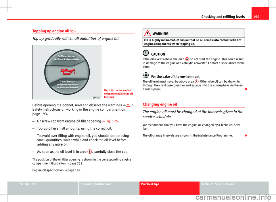
Fig. 125 In the engine
compartment: Engine oil
filler cap
Before opening the bonnet, read and observe the warnings ⇒
in
Safety instructions on working in the engine compartment on
page 193.
– Unscrew cap from engine oil filler opening ⇒ Fig. 125.
– Top-up oil in small amounts, using the correct oil.
– To avoid over-filling with engine oil, you should top-up using
small quantities, wait a while and check the oil level before
adding any more oil.
– As soon as the oil level is in area B
, carefully close the cap.
The position of the oil filler opening is shown in the corresponding engine
compartment illustration ⇒ page 251.
Engine oil specification ⇒ page 197.
WARNING
Oil is highly inflammable! Ensure that no oil comes into contact with hot
engine components when topping up.
CAUTION
If the oil level is above the area A do not start the engine. This could result
in damage to the engine and catalytic converter. Contact a specialised work-
shop.
For the sake of the environment
The oil level must never be above area A. Otherwise oil can be drawn in
through the crankcase breather and escape into the atmosphere via the ex-
haust system.
Changing engine oil
The engine oil must be changed at the intervals given in the
service schedule. We recommend that you have the engine oil changed by a Technical Serv-
ice.
The oil change intervals are shown in the Maintenance Programme.
Safety FirstOperating InstructionsPractical TipsTechnical Specifications