sensor Seat Ibiza ST 2011 User Guide
[x] Cancel search | Manufacturer: SEAT, Model Year: 2011, Model line: Ibiza ST, Model: Seat Ibiza ST 2011Pages: 280, PDF Size: 4.01 MB
Page 103 of 280
101
Lights and visibility
Home lighting comes on. If the driver door is already open when the lights
are flashed briefly, the Coming Home lighting comes on immediately.
When the last door of the vehicle or the tailgate is closed, the Coming Home
function starts and the switching off the headlights is delayed.
The Coming Home lighting switches off in the following cases:
● On completion of the time period established for the delay in switching
off the lights after all the vehicle doors and the tailgate have been closed.
● If, 30 seconds after being connected, any doors or the tailgate remain
open.
● If the light switch is turned to position .
● If the ignition is switched on.
Leaving home function
The Leaving Home function is activated when the vehicle is unlocked if:
● the light control is in position and
● the photosensor detects “darkness”.
The Leaving Home lighting switches off in the following cases:
● If the time period for the delay in switching off the headlights has ended
● If the vehicle is locked again.
● If the light switch is turned to position .
● If the ignition is switched on.
Note
● To activate the coming/leaving home function, the rotary light switch
must be in position and the light sensor must detect darkness.
● If the ignition key is removed while the lights are on, and the lights are
flashed briefly and the driver door opened, no acoustic signal is heard, as
when the Coming Home function is on, the lights are automatically switched
off after a period of time (except when the light switch is in position or
.
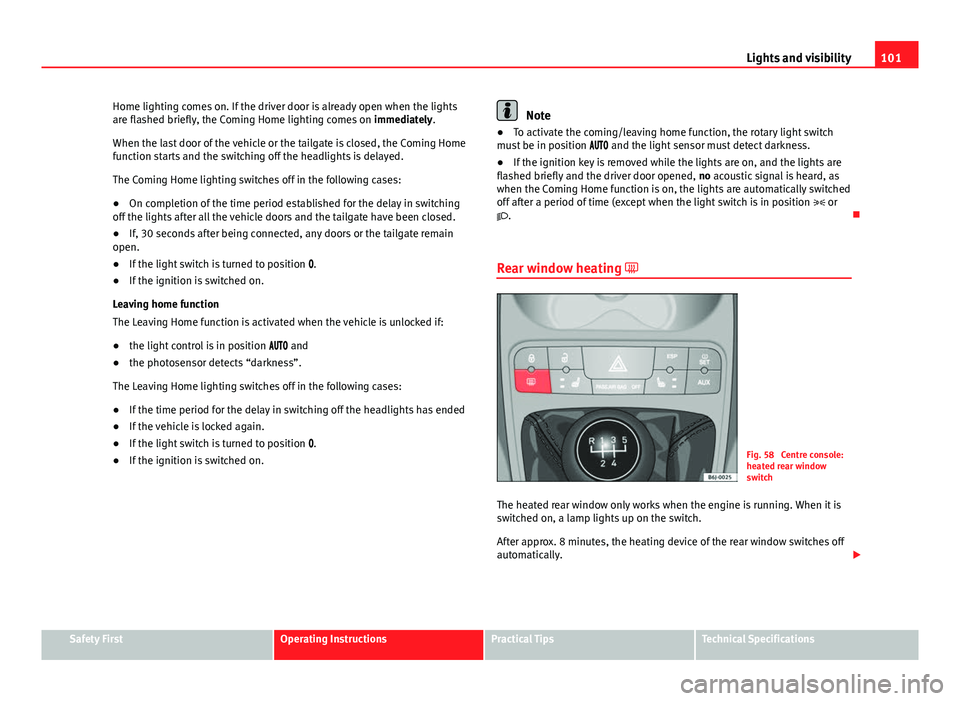
Rear window heating
Fig. 58 Centre console:
heated rear window
switch
The heated rear window only works when the engine is running. When it is
switched on, a lamp lights up on the switch.
After approx. 8 minutes, the heating device of the rear window switches off
automatically.
Safety FirstOperating InstructionsPractical TipsTechnical Specifications
Page 109 of 280
107
Lights and visibility
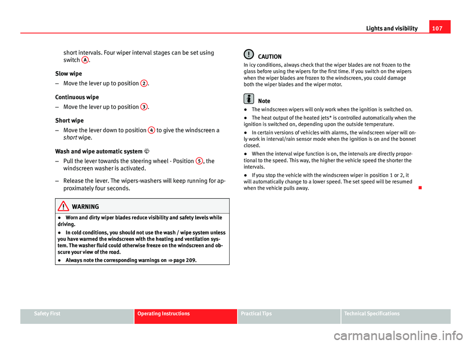
short intervals. Four wiper interval stages can be set using
switch A
.
Slow wipe
– Move the lever up to position 2
.
Continuous wipe
– Move the lever up to position 3
.
Short wipe
– Move the lever down to position 4
to give the windscreen a
short wipe.
Wash and wipe automatic system
– Pull the lever towards the steering wheel - Position 5
, the
windscreen washer is activated.
– Release the lever. The wipers-washers will keep running for ap-
proximately four seconds.
WARNING
● Worn and dirty wiper blades reduce visibility and safety levels while
driving.
● In cold conditions, you should not use the wash / wipe system unless
you have warmed the windscreen with the heating and ventilation sys-
tem. The washer fluid could otherwise freeze on the windscreen and ob-
scure your view of the road.
● Always note the corresponding warnings on ⇒ page 209.
CAUTION
In icy conditions, always check that the wiper blades are not frozen to the
glass before using the wipers for the first time. If you switch on the wipers
when the wiper blades are frozen to the windscreen, you could damage
both the wiper blades and the wiper motor.
Note
● The windscreen wipers will only work when the ignition is switched on.
● The heat output of the heated jets* is controlled automatically when the
ignition is switched on, depending upon the outside temperature.
● In certain versions of vehicles with alarms, the windscreen wiper will on-
ly work in interval/rain sensor mode when the ignition is on and the bonnet
closed.
● When the interval wipe function is on, the intervals are directly propor-
tional to the speed. This way, the higher the vehicle speed the shorter the
intervals.
● If you stop the vehicle with the windscreen wiper in position 1 or 2, it
will automatically change to a lower speed. The set speed will be resumed
when the vehicle pulls away.
Safety FirstOperating InstructionsPractical TipsTechnical Specifications
Page 110 of 280
108Lights and visibility
Rain sensor*
The rain sensor controls the frequency of the windscreen
wiper intervals, depending on the amount of rain.
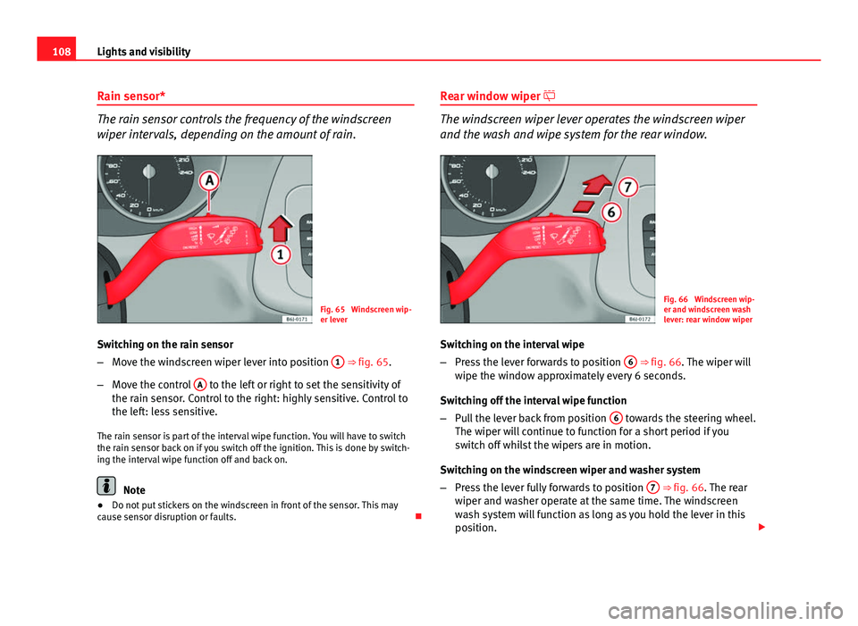
Fig. 65 Windscreen wip-
er lever
Switching on the rain sensor
– Move the windscreen wiper lever into position 1
⇒ fig. 65.
– Move the control A
to the left or right to set the sensitivity of
the rain sensor. Control to the right: highly sensitive. Control to
the left: less sensitive.
The rain sensor is part of the interval wipe function. You will have to switch
the rain sensor back on if you switch off the ignition. This is done by switch-
ing the interval wipe function off and back on.
Note
● Do not put stickers on the windscreen in front of the sensor. This may
cause sensor disruption or faults. Rear window wiper
The windscreen wiper lever operates the windscreen wiper
and the wash and wipe system for the rear window.
Fig. 66 Windscreen wip-
er and windscreen wash
lever: rear window wiper
Switching on the interval wipe
– Press the lever forwards to position 6
⇒ fig. 66. The wiper will
wipe the window approximately every 6 seconds.
Switching off the interval wipe function
– Pull the lever back from position 6
towards the steering wheel.
The wiper will continue to function for a short period if you
switch off whilst the wipers are in motion.
Switching on the windscreen wiper and washer system
– Press the lever fully forwards to position 7
⇒ fig. 66. The rear
wiper and washer operate at the same time. The windscreen
wash system will function as long as you hold the lever in this
position.
Page 112 of 280
110Lights and visibility
Automatic anti-dazzle interior mirror*
The automatic anti-dazzle function can be switched on and
off as desired.
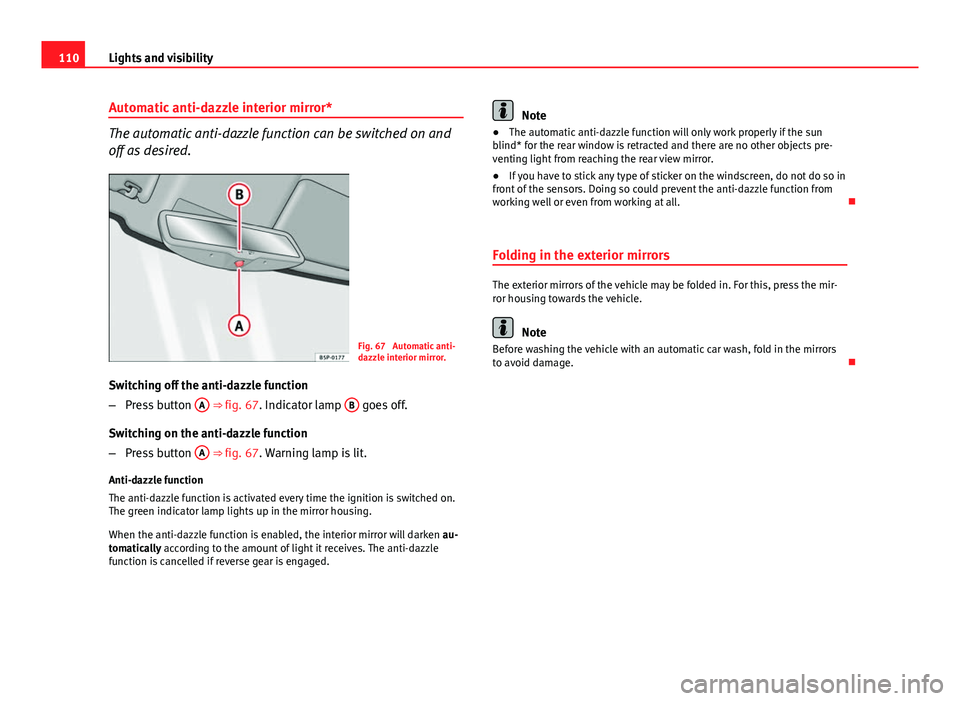
Fig. 67 Automatic anti-
dazzle interior mirror.
Switching off the anti-dazzle function
– Press button A
⇒ fig. 67. Indicator lamp B goes off.
Switching on the anti-dazzle function
– Press button A
⇒ fig. 67. Warning lamp is lit.
Anti-dazzle function
The anti-dazzle function is activated every time the ignition is switched on.
The green indicator lamp lights up in the mirror housing.
When the anti-dazzle function is enabled, the interior mirror will darken au-
tomatically according to the amount of light it receives. The anti-dazzle
function is cancelled if reverse gear is engaged.
Note
● The automatic anti-dazzle function will only work properly if the sun
blind* for the rear window is retracted and there are no other objects pre-
venting light from reaching the rear view mirror.
● If you have to stick any type of sticker on the windscreen, do not do so in
front of the sensors. Doing so could prevent the anti-dazzle function from
working well or even from working at all.
Folding in the exterior mirrors
The exterior mirrors of the vehicle may be folded in. For this, press the mir-
ror housing towards the vehicle.
Note
Before washing the vehicle with an automatic car wash, fold in the mirrors
to avoid damage.
Page 163 of 280
161
Driving
WARNING
● Take measures to reduce the risk of injury when you leave your vehi-
cle unattended.
● Never park where the hot exhaust system could ignite inflammable
materials, such as dry grass, low bushes, spilt fuel etc.
● Never allow vehicle occupants to remain in the vehicle when it is
locked. They would be unable to open the vehicle from the inside, and
could become trapped in the vehicle in an emergency. In the event of an
emergency, locked doors will delay assistance to occupants.
● Never leave children alone in the vehicle. They could set the vehicle
in motion, for example, by releasing the handbrake or the gear lever.
● Depending on weather conditions, it may become extremely hot or
cold inside the vehicle. This can be fatal.
Hill-start assist*
This function is only included in vehicles with ESP. This device helps when starting uphill.
These are the basic operation conditions: doors closed, brake pedal press-
ed down and vehicle in neutral. The system gets activated on engaging
gear.
After removing your foot from the brake pedal, the braking force is main-
tained for a few seconds to prevent the vehicle from moving backward when
putting into gear. This short space of time is enough to start the vehicle
with ease.
This system also works when reversing uphill.
WARNING
● If you do not start the vehicle immediately after taking your foot off
the brake pedal, the vehicle may start to roll back under certain condi-
tions. Depress the brake pedal or use the hand brake immediately.
● If the engine stalls, depress the brake pedal or use the hand brake
immediately.
● When following a line of traffic uphill, if you want to prevent the vehi-
cle from rolling back accidentally when starting off, hold the brake pedal
down for a few seconds before starting off.
Note
The Official Service or a specialist workshop can tell you if your vehicle is
equipped with this system.
Acoustic parking aid system* Rear parking aid
The parking aid system will use an acoustic signal to warn of
the approach of any object towards the rear of the vehicle.
Description
The acoustic parking aid system will measure the distance between the rear
of the vehicle and any possible obstacle using four ultrasonic sensors loca-
ted on the rear bumper. The measuring range of the sensors starts approxi-
mately and depending on the nature of the obstacle at a distance of:
● side of the rear bumper: 0.6 m
● middle of the rear bumper: 1.6 m
Safety FirstOperating InstructionsPractical TipsTechnical Specifications
Page 164 of 280
162Driving
Activation
The system is activated by engagement of the reverse gear. A brief acoustic
signal confirms the activation and correct function of the system.
Reverse gear
The distance warning will begin as soon as an obstacle is detected by the
system. The frequency of the bleeps emitted by the system will increase rap-
idly as the vehicle approaches the obstacle.
Within a short distance of about 30cm, a continuous signal sounds (stop
signal). The driver should not reverse any further.
Models with a factory-fitted towing bracket: When the vehicle is less than
0.35 m away from the obstacle the warning tone will sound continuously.
The driver should then not reverse any further.
The warning tone decreases by 30% after 3 seconds from the start of the
system.
Provided that it is not in continuous mode, the tone on the parking aid sys-
tem stops when it detects a wall parallel to the vehicle.
Trailer towing
For vehicles factory-fitted with a towing bar, the parking aid system will not
be activated by the engagement of the reverse gear when pulling a trailer,
as the trailer's electric connector will be plugged into the vehicle.
Possible faults
If a continuous beep sounds for some seconds when the reverse gear is en-
gaged, this indicates that there is a fault in the parking aid system.
If the fault continues until the ignition is turned off, the acoustic signal
warning of the fault will not be emitted every time the system is reactivated
(by engaging the reverse gear). Thus, the system ready indication will not
sound either. Have the fault repaired by an Authorised Service Centre as
soon as possible. If there is no ready signal or no acoustic warning signal, then the parking
aid loudspeaker is faulty and may not warn of obstacles.
To ensure that the system works properly, the sensors must be kept clean
and free of ice and snow.
WARNING
● The sensors have blind spots in which obstacles may not be detected.
● Always look out for small children and animals because the system
will not always detect them. Always pay attention when reversing to
avoid accidents.
● The parking aid is not a replacement for driver awareness. The driver
must take full responsibility for parking and other manoeuvres.
CAUTION
● Please note that low obstacles detected by the system may no longer be
registered by the sensors as the car moves closer, so the system will not
give any further warning. Certain kinds of obstacles (such as wire fences,
chains, thin posts or trailer draw bars, high kerbs or painted railings etc)
may not always be detected by the system, so there is a risk of damaging
the vehicle in such cases.
● In some cases, obstacles with uniform edges and bumps may not be de-
tected immediately by the system due to their geometry. Take special care
of this type of obstacle (corners, rectangular objects, etc.), as they can
cause damage to the vehicle.
● Be especially careful when manoeuvring into a corner between two per-
pendicular walls. Carefully watch the approach of the wall to the side of the
vehicle (using the mirrors).
● The parking aid system does not replace use of the mirrors for manoeu-
vres.
Page 165 of 280
163
Driving
● External ultra-sonic sources (pneumatic drills, construction machinery,
other vehicles with PDC) may interfere with the operation of the system.
● Periodic cleaning of the sensors, take care not to damage or scratch
them. When cleaning with high pressure washers or steam cleaners, the
sensors should be sprayed for only a very short period and from a distance
of more than 10 cm.
Cruise speed* (Cruise control system)
Description
The cruise control system is able to maintain the set speed
in the range of 30 km/h to 180 km/h. Once the speed setting has been saved, you may take your foot off the ac-
celerator.
WARNING
It could be dangerous to use the cruise control system if it is not possible
to drive at constant speed.
● Do not use the cruise control system when driving in dense traffic, on
roads with lots of bends or on roads with poor conditions (with ice, slip-
pery surfaces, loose grit or gravel), as this could cause an accident.
● Always switch the cruise control system off after using it in order to
avoid an involuntary use.
● It is dangerous to use a set speed which is too high for the current
road, traffic or weather conditions. Risk of accident.
Note
The cruise control cannot maintain a constant speed when descending
downhill. The vehicle will accelerate due to its own weight. Use the foot
brake to slow the vehicle.
Switching the cruise control system on and off
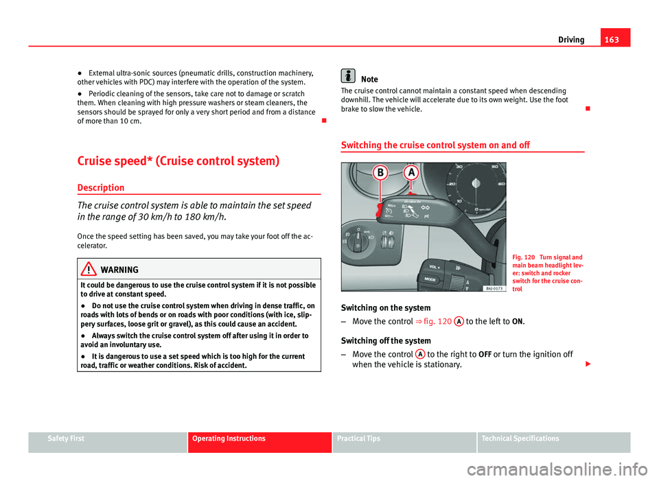
Fig. 120 Turn signal and
main beam headlight lev-
er: switch and rocker
switch for the cruise con-
trol
Switching on the system
– Move the control ⇒ fig. 120 A
to the left to
ON.
Switching off the system
– Move the control A
to the right to
OFF or turn the ignition off
when the vehicle is stationary.
Safety FirstOperating InstructionsPractical TipsTechnical Specifications
Page 171 of 280
169
Intelligent technology
TCS helps the vehicle to start moving, accelerate and climb a gradient in
slippery conditions where this may otherwise be difficult or even impossi-
ble.
The TCS is switched on automatically when the engine is started. If necessa-
ry, it may be turned on or off by briefly pushing the ESP button on the centre
console.
When the TCS is off, the warning lamp is lit. The TCS should normally be
left on. Only in exceptional circumstances, when the slipping of the wheels
is required, can they be disconnected using the ESP button, for example.
● With compact temporary spare wheel.
● When using the snow chains.
● When driving in deep snow or on loose surfaces
● When the vehicle is bogged-down, to free it by rocking.
The TCS should be switched on again as soon as possible.
WARNING
● It must be remembered that TCS cannot defy the laws of physics. This
should be kept in mind, particularly on slippery and wet roads and when
towing a trailer.
● Always adapt your driving style to suit the condition of the roads and
the traffic situation. Do not let the extra safety afforded by TCS tempt you
into taking any risks when driving, this can cause accidents.
CAUTION
● In order to ensure that TCS function correctly, all four wheels must be fit-
ted with the same tyres. Any differences in the rolling radius of the tyres can
cause the system to reduce engine power when this is not desired.
● Modifications to the vehicle (e.g. to the engine, the brake system, run-
ning gear or any components affecting the wheels and tyres) could affect
the efficiency of the ABS and TCS. XDS*
Driveshaft differential
When taking a bend, the driveshaft differential mechanism allows the outer
wheel to turn at a higher speed than the inner wheel. In this way, the wheel
that is turning faster (outer wheel) receives less drive torque than the inner
wheel. This may mean that in certain situations the torque delivered to the
inner wheel is too high, causing the wheels to spin. On the other hand, the
outer wheel is receiving a lower drive torque than it could transmit. This
causes an overall loss of lateral grip on the front axle, resulting in under-
steer or “lengthening” of the trajectory.
By using the ESP sensors and signals, the XDS system is able to detect and
correct this effect.
Through the ESP, the XDS brakes the inner wheel, thereby counteracting the
excess drive torque in this wheel. This means that the driver's desired tra-
jectory is much more precise,
The XDS system operates in combination with the ESP and is always active,
even when the traction control, TCS, is disconnected.
Electronic Stability Programme (ESP)* General notes
The Electronic Stability Programme increases the vehicle's
stability on the road.
The Electronic Stability Programme helps reduce the danger of skidding.
The Electronic Stability Programme (ESP) consists of ABS, EDL and TCS.
Safety FirstOperating InstructionsPractical TipsTechnical Specifications
Page 172 of 280
170Intelligent technology
Electronic Stability Programme (ESP)*
ESP reduces the danger of skidding by braking the wheels individually.
The system uses the steering wheel angle and road speed to calculate the
changes of direction desired by the driver, and constantly compares them
with the actual behaviour of the vehicle. If the desired course is not being
maintained (for instance, if the vehicle is starting to skid), then the ESP
compensates automatically by braking the appropriate wheel.
The forces acting on the braked wheel bring the vehicle back to a stable
condition. If the vehicle tends to oversteer, the system will act on the front
wheel on the outside of the turn.
WARNING
● It must be remembered that ESP cannot defy the laws of physics. This
should be kept in mind, particularly on slippery and wet roads and when
towing a trailer.
● Always adapt your driving style to suit the condition of the roads and
the traffic situation. Do not let the extra safety afforded by ESP tempt you
into taking any risks when driving, as this can cause accidents.
CAUTION
● In order to ensure that ESP functions correctly, all four wheels must be
fitted with the same tyres. Any differences in the rolling radius of the tyres
can cause the system to reduce engine power when this is not desired.
● Modifications to the vehicle (e.g. to the engine, the brake system, run-
ning gear or any components affecting the wheels and tyres) could affect
the efficiency of the ABS, EDL, ESP and TCS. Anti-lock brake system (ABS)
The anti-lock brake system prevents the wheels locking during braking
⇒ page 168.
Electronic differential lock (EDL)*
The electronic differential lock helps prevent the loss of trac-
tion caused if one of the driven wheels starts spinning.
EDL helps the vehicle to start moving, accelerate and climb a gradient in
slippery conditions where this may otherwise be difficult or even impossi-
ble.
The system will control the revolutions of the drive wheels using the ABS
sensors (in case of an EDL fault the warning lamp for ABS lights up)
⇒ page 69.
At speeds of up to approximately 80 km/h, it is able to balance out differen-
ces in the speed of the driven wheels of approximately 100 rpm caused by a
slippery road surface on one side of the vehicle. It does this by braking the
wheel which has lost traction and distributing more driving force to the oth-
er driven wheel via the differential.
To prevent the disc brake of the braking wheel from overheating, the EDL
cuts out automatically if subjected to excessive loads. The vehicle will con-
tinue to function normally without EDL. For this reason, the driver is not in-
formed that the EDL has been switched off.
The EDL will switch on again automatically when the brake has cooled
down.
Page 232 of 280
230If and when
Note
● If a newly replaced fuse blows again after a short time, the electrical sys-
tem must be checked by a specialised workshop as soon as possible.
● If you replace a fuse with higher-rating fuse, you could cause damage to
another location in the electrical system.
● Always keep some spare fuses in the vehicle. These are available from
SEAT dealers.
Fuses on left side of dash panel
Fuses
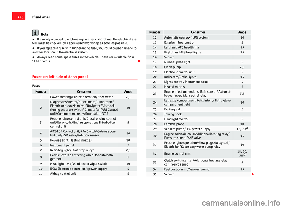
NumberConsumerAmps1Power steering/Engine operation/Flow meter7,5
2
Diagnostics/Heater/Autoclimate/Climatronic/
Electric anti-dazzle mirror/Navigator/Air condi-
tioning pressure switch/ Climate fan/AFS Control
unit/Coming home relay/Soundaktor/CCS
10
3Petrol engine control unit/Diesel engine control
unit/Relay coils/Engine operation/Bi-turbo fuel
control unit5
4ABS-ESP Control unit/RKA Switch/Gateway con-
trol unit/ESP Relay/Rotation sensor10
5Reverse light/Heating nozzles106Instrument panel57Retro fog light/Start-Stop relays7,5
8Paddle levers on steering wheel for automatic
gearbox2
9Headlight lever/Windscreen wiper switch1010BCM Electronic control unit power supply511Airbag control unit5
NumberConsumerAmps12Automatic gearbox/ LPG system1013Exterior mirror control514Left-hand AFS headlights1515Right-hand AFS headlights1516Vacant 17Number plate light518Clean pump7,519Electronic control unit520Indicators/Brake lights1521Lights control, instrument panel522Heated mirrors5
23Engine injection module/ Rain sensor/ Automat-
ic gear lever/ Main petrol relay7,5
24Luggage compartment light, interior light, glove
compartment light10
25Parking aid526Towing hook 27Headlight control528Lambda probe1029Vacuum pump/LPG power supply15, 20 a)
30Engine solenoid coils/Additional heating relay/
Pressure sensor/AKF Valve15
31Petrol engine operation/Glow plugs/Relay coil/
Electric fan/Secondary water pump relay10
32Engine control unit15, 20,
30 b)
33Clutch switch sensor/Additional heating relay
coil/ Servo sensor5
34Fuel control unit / Vacuum pump1535Vacant