technical specifications Seat Ibiza ST 2011 Owner's Guide
[x] Cancel search | Manufacturer: SEAT, Model Year: 2011, Model line: Ibiza ST, Model: Seat Ibiza ST 2011Pages: 280, PDF Size: 4.01 MB
Page 45 of 280
43
Child safety
Child safety
Brief introduction Introduction
Statistics show that children are generally safer on the rear
seat than on the front passenger seat.For safety reasons we recommend that children under 12 years of age travel
on the rear seats. Depending on their age, height and weight, children trav-
elling on the rear seat must use a child seat or a seat belt. For safety rea-
sons, the child seat should be installed in the centre of the rear seat or be-
hind the front passenger seat.
The physical laws involved and the forces acting in a collision apply also to
children. ⇒ page 21, Why wear seat belts?. But unlike adults, children do
not have muscle and bone structures fully developed. This means that chil-
dren are subject to a greater risk of injury.
To reduce this risk, children must always use special child restraint systems
when travelling in the vehicle.
We recommend the use of child safety products from the SEAT Genuine Ac-
cessories Programme, which includes systems for all ages made by Peke 1)
.
These systems have been especially designed and approved, complying
with the ECE-R44. regulation.
Follow the manufacturer's instructions and observe any statutory require-
ments when installing and using child seats. Always read and note
⇒ page 43, Safety notes on using child seats. We recommend you to include the manufacturer's Child Seat instruction
manual together with the on-board documentation.
Safety notes on using child seats
Proper use of child seats substantially reduces the risk of in-
jury in an accident! As the driver, you are responsible for any children you transport in
your vehicle.
– Protect your children by properly using the appropriate child
seats ⇒ page 45.
– Always ensure that the seat belt is properly positioned accord-
ing to the instructions provided by the manufacturer of the child
seat.
– When travelling, do not allow children to distract you from traf-
fic.
– Take breaks regularly during long trips. Take a break at least ev-
ery two hours.
1)
Not for all countries
Safety FirstOperating InstructionsPractical TipsTechnical Specifications
Page 47 of 280
45
Child safety
Child seats
Categorisation of child seats into groups
Use only child seats that are officially approved and suitable
for the child. Child seats are subject to the regulation ECE-R 44. ECE-R stands for: Eco-
nomic Commission for Europe Regulation
The child seats are grouped into 5 categories: Group 0: up to 10 kg
Group 0+: up to 13 kg
Group 1: from 9 to 18 kg
Group 2: from 15 to 25 kg
Group 3: from 22 to 36 kg
Child seats that have been tested and approved under the ECE R44 stand-
ard bear the test mark on the seat (the letter E in a circle with the test num-
ber below it). Group 0 and 0+ child seats
A suitable child seat and a correctly adjusted seat belt can
help you to protect your child.
Fig. 23 A group 0 rear-
facing child seat fitted on
the rear seat.
Group 0: For babies from about 9 months old and 10 kg in weight, the most
suitable seats are those appearing in the illustration ⇒ fig. 23.
Group 0+: For babies from about 18 months old and 13 kg in weight, the
most suitable seats are those appearing in the figure ⇒ fig. 23.
Follow the manufacturer's instructions and observe any statutory require-
ments when installing and using child seats.
We recommend you to include the manufacturer's Child Seat instruction
manual together with the on-board documentation.
WARNING
Read and always observe information and warnings concerning the use
of child seats ⇒
in Safety notes on using child seats on page 44.
Safety FirstOperating InstructionsPractical TipsTechnical Specifications
Page 49 of 280
47
Child safety
WARNING
● The shoulder part of the seat belt must lie approximately on the cen-
tre of the shoulder, never across the neck or the arm. The seat belt must
lie close to the upper part of the body. The lap belt part must lie across
the pelvis, not across the stomach, and always fit closely. Pull the belt
tight if necessary to take up any slack ⇒ page 25, Seat belts.
● Read and always observe information and warnings concerning the
use of child seats ⇒
in Safety notes on using child seats on page 44.
Safety FirstOperating InstructionsPractical TipsTechnical Specifications
Page 51 of 280
49
Child safety
When removing or fitting the child seat, please be sure to follow
the manufacturer's instructions.
– Press the child seat onto the ISOFIX retaining rings until the
child seat can be heard to engage securely. If the child seat is
fitted with any other anti-rotation system, follow the manufac-
turer instructions carefully.
– Pull on both sides of the child seat to ensure that it is secure.
Two ISOFIX retaining rings are fitted on each rear seat. In some vehicles, the
rings are secured to the seat frame and, in others, they are secured to the
rear floor. The access to the ISOFIX rings is between the rear seat backrest
and the seat cushioning.
Child seats with ISOFIX mountings are available in your Authorised Service
Centres.
WARNING
● The retaining rings are designed to only be used with ISOFIX child
seats.
● Never secure child seats without the ISOFIX system, retaining belts or
objects to the fastening rings – this can result in potentially fatal injuries
to the child.
● Ensure that the child seat is secured correctly to the ISOFIX anchor
points.
Top Tether retainer straps
Some child restraint seats have a third Top Tether anchoring
point, apart from both ISOFIX anchoring points, which allow
better child retention.
Fig. 27 Position of the
Top Tether rings on the
back of the rear seat
Child seats with the Top Tether system come with a strap for securing the
seat to the vehicle anchor point, located at the back of the rear backrest.
The retainer strap is used to reduce forwards movements of the safety seat
in a crash, helping reduce the risk of injuries to the head from hitting the
inside of the vehicle.
It is foreseen that an EU Directive will introduce requirements related to the
retention of child restraint systems by means of ISOFIX and Top Tether an-
chorages (probably compulsory for new types from 2010), which will entail
improved retention of the child restraint seat and less head movement in
case of frontal collisions.
Safety FirstOperating InstructionsPractical TipsTechnical Specifications
Page 53 of 280
51
Child safety
Safety FirstOperating InstructionsPractical TipsTechnical Specifications
Page 55 of 280
53
Cockpit
Operating Instructions Cockpit
Overview Overview of the dash panel
This overview will help you to familiarise yourself with the
controls and displays. Door release lever
Light switch . . . . . . . . . . . . . . . . . . . . . . . . . . . . . . . . . . . . . . . . . . . . . . . 97
Light dimmer for instrument panel lighting* . . . . . . . . . . . . . . . .99
Headlight range control* . . . . . . . . . . . . . . . . . . . . . . . . . . . . . . . . . . 99
Air vent
Lever for:
– turn signals/dipped beam . . . . . . . . . . . . . . . . . . . . . . . . . . . . . . 103
– cruise control* . . . . . . . . . . . . . . . . . . . . . . . . . . . . . . . . . . . . . . . . . 163
Instrument panel and warning lamps:
– Instruments . . . . . . . . . . . . . . . . . . . . . . . . . . . . . . . . . . . . . . . . . . . . 55
– Indicator lamps . . . . . . . . . . . . . . . . . . . . . . . . . . . . . . . . . . . . . . . . . 63
Horn (only works when the ignition is on)/ and driver
front airbag* . . . . . . . . . . . . . . . . . . . . . . . . . . . . . . . . . . . . . . . . . . . . . . 30
Steering and starter lock . . . . . . . . . . . . . . . . . . . . . . . . . . . . . . . . . . 143
Lever for:
– windscreen wiper/washer . . . . . . . . . . . . . . . . . . . . . . . . . . . . . . . 106
– rear window wiper/washer* . . . . . . . . . . . . . . . . . . . . . . . . . . . . . 106
– multifunction display* . . . . . . . . . . . . . . . . . . . . . . . . . . . . . . . . . . 59
1
23456
7
8
910
Radio
Glove compartment/Storage compartment
. . . . . . . . . . . . . . . . .120
Passenger airbag* . . . . . . . . . . . . . . . . . . . . . . . . . . . . . . . . . . . . . . . . 34
Switches for:
– Heating and ventilation . . . . . . . . . . . . . . . . . . . . . . . . . . . . . . . . . 132
– Air conditioning* . . . . . . . . . . . . . . . . . . . . . . . . . . . . . . . . . . . . . . . 135
– Climatronic* . . . . . . . . . . . . . . . . . . . . . . . . . . . . . . . . . . . . . . . . . . . . 138
Cigarette lighter / Power socket . . . . . . . . . . . . . . . . . . . . . . . . . . . . 123
Cup holder/Ashtray . . . . . . . . . . . . . . . . . . . . . . . . . . . . . . . . . . . . . . . 122
Controls on the centre console:
– Hazard warning lights . . . . . . . . . . . . . . . . . . . . . . . . . . . . . . . . . . 102
– Airbag disconnection warning light* . . . . . . . . . . . . . . . . . . . . .31
– ESP . . . . . . . . . . . . . . . . . . . . . . . . . . . . . . . . . . . . . . . . . . . . . . . . . . . . 169
– Tyre pressure monitoring* . . . . . . . . . . . . . . . . . . . . . . . . . . . . . . . 71
– Heated rear window . . . . . . . . . . . . . . . . . . . . . . . . . . . . . . . . . . . . 101
– Heated seats* . . . . . . . . . . . . . . . . . . . . . . . . . . . . . . . . . . . . . . . . . . 117
– Central locking* . . . . . . . . . . . . . . . . . . . . . . . . . . . . . . . . . . . . . . . . 82
– AUX connection . . . . . . . . . . . . . . . . . . . . . . . . . . . . . . . . . . . . . . . . 125
Handbrake lever . . . . . . . . . . . . . . . . . . . . . . . . . . . . . . . . . . . . . . . . . . 159
Gear lever
– automatic* . . . . . . . . . . . . . . . . . . . . . . . . . . . . . . . . . . . . . . . . . . . . . 152
– manual . . . . . . . . . . . . . . . . . . . . . . . . . . . . . . . . . . . . . . . . . . . . . . . . 151
Storage space
Pedals . . . . . . . . . . . . . . . . . . . . . . . . . . . . . . . . . . . . . . . . . . . . . . . . . . . . 16
11121314
151617
1819
2021
Safety FirstOperating InstructionsPractical TipsTechnical Specifications
Page 57 of 280
55
Cockpit
Instruments Instrument overview
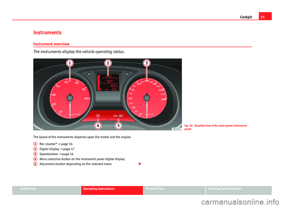
The instruments display the vehicle operating status.
Fig. 30 Detailed view of the dash panel: instrument
panel
The layout of the instruments depends upon the model and the engine. Rev counter* ⇒ page 56
Digital display ⇒ page 57
Speedometer ⇒ page 56
Menu selection button on the instrument panel digital display
Adjustment button depending on the selected menu
12345
Safety FirstOperating InstructionsPractical TipsTechnical Specifications
Page 59 of 280
57
Cockpit
WARNING
LPG is a highly explosive and inflammable substance. It may cause se-
vere burns and other injury.
● Due care must be taken to avoid any risk of fire or explosion.
● When parking the vehicle in a closed area (for example in a garage),
make sure that there is adequate ventilation, either natural or mechani-
cal, to neutralise the LPG in the event of a leak.
Note
● The values shown in the average fuel consumption and distance to emp-
ty indications on the multifunction display (MFI) 1)
on the instrument panel 2)
are approximate values only.
● Two different consumption values are given on the MFI, depending on
whether the vehicle is running in GAS or Petrol mode.
● Please check the fuel level on the fuel level gauge on the instrument
panel ⇒ page 57
● If frequent short journeys are made, especially when the outside tem-
perature is low, the vehicle will tend to run on petrol more often than on
LPG. Therefore, the petrol tank may empty before the LPG tank. Digital instrument panel display
Fuel gauge and reserve indicator
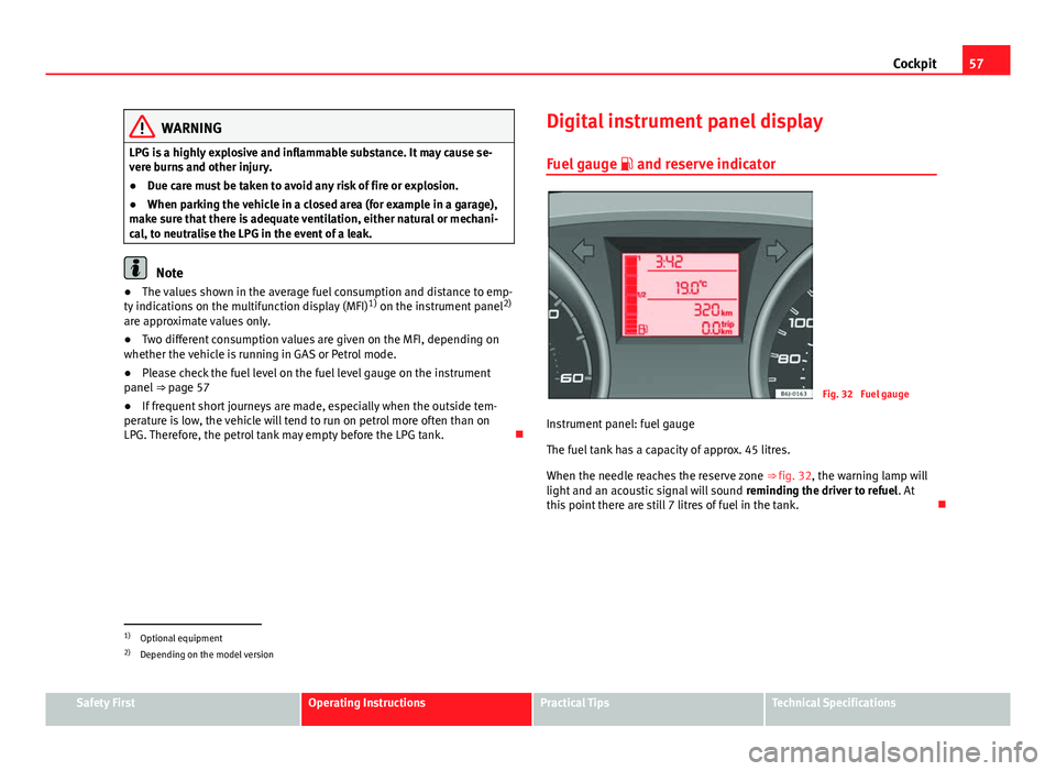
Fig. 32 Fuel gauge
Instrument panel: fuel gauge
The fuel tank has a capacity of approx. 45 litres.
When the needle reaches the reserve zone ⇒ fig. 32, the warning lamp will
light and an acoustic signal will sound reminding the driver to refuel. At
this point there are still 7 litres of fuel in the tank.
1)
Optional equipment
2) Depending on the model version
Safety FirstOperating InstructionsPractical TipsTechnical Specifications
Page 61 of 280
59
Cockpit
Multifunction display (MFI)*
The multifunction display (MFI) shows you information on
the journey and fuel consumption.
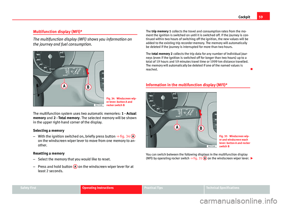
Fig. 34 Windscreen wip-
er lever: button A and
rocker switch B
The multifunction system uses two automatic memories: 1 - Actual
memory and 2 - Total memory . The selected memory will be shown
in the upper right-hand corner of the display.
Selecting a memory
– With the ignition switched on, briefly press button ⇒ fig. 34 A
on the windscreen wiper lever to move from one memory to an-
other.
Resetting a memory
– Select the memory that you would like to reset.
– Press and hold button A
on the windscreen wiper lever for at
least 2 seconds. The trip memory 1
collects the travel and consumption rates from the mo-
ment the ignition is switched on until it is switched off. If the journey is con-
tinued within two hours of switching off the ignition, the new values will be
added to the existing trip recorder memory. The memory will automatically
be deleted if the journey is interrupted for more than two hours.
The total memory 2 collects the trip data for any number of individual jour-
neys (even if the ignition is switched off for longer than two hours) up to a
total of 19 hours and 59 minutes travel time or 1999 km distance travelled.
The memory will automatically be deleted if one of the named values is
reached.
Information in the multifunction display (MFI)*
Fig. 35 Windscreen wip-
er and windscreen wash
lever: button A and rocker
switch B
You can switch between the following displays in the multifunction display
(MFI) by operating rocker switch ⇒ fig. 35 B
on the windscreen wiper lever.
Safety FirstOperating InstructionsPractical TipsTechnical Specifications
Page 63 of 280
61
Cockpit
This may be deactivated by pressing the RESET
button. The speed may be
altered using the rocker switch B in steps of 5 km/h within 5 seconds of
the initial memory value.
WARNING
There could be black ice on the road surface even if the “snowflake sym-
bol” is not shown. For this reason you should not rely exclusively on this
display - Risk of accident!
Note
When the vehicle is stationary or travelling at very low speeds, the tempera-
ture displayed may be slightly higher than the actual outside temperature
as a result of the heat radiated from the engine.
Display field for selector lever position*
Fig. 36 Digital display:
Gear lever position for
automatic gearbox. The position of the automatic selector lever is shown on the display
⇒ page 152.
Odometer
The upper counter in the display registers the total mileage covered by the
vehicle.
The lower counter registers the short journeys. The last digit indicates 100-
metre sections. The trip recorder counter may be reset by pressing the reset
button ⇒ fig. 30 5
.
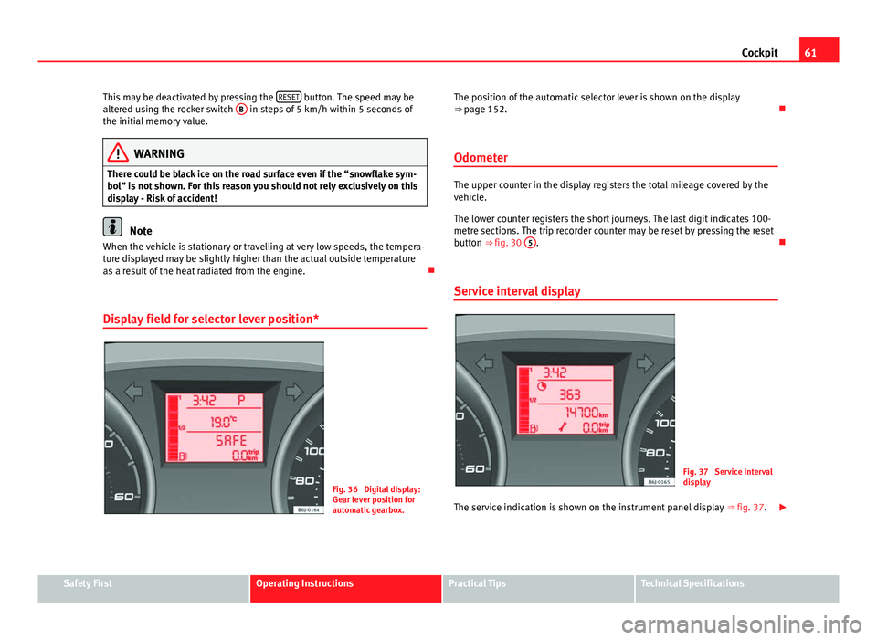
Service interval display
Fig. 37 Service interval
display
The service indication is shown on the instrument panel display ⇒ fig. 37.
Safety FirstOperating InstructionsPractical TipsTechnical Specifications