engine Seat Ibiza ST 2011 Manual Online
[x] Cancel search | Manufacturer: SEAT, Model Year: 2011, Model line: Ibiza ST, Model: Seat Ibiza ST 2011Pages: 280, PDF Size: 4.01 MB
Page 210 of 280
208Checking and refilling levels
Washer fluid and windscreen wiper blades
Topping up washer fluid
The water for cleaning the windscreen should always be
mixed with washer fluid.
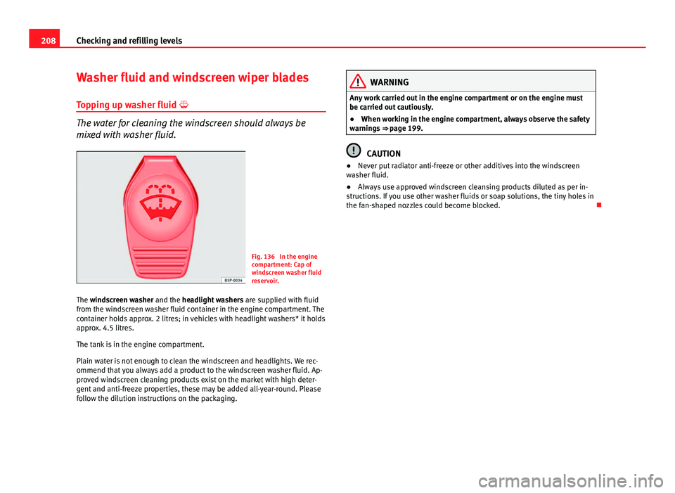
Fig. 136 In the engine
compartment: Cap of
windscreen washer fluid
reservoir.
The windscreen washer and the headlight washers are supplied with fluid
from the windscreen washer fluid container in the engine compartment. The
container holds approx. 2 litres; in vehicles with headlight washers* it holds
approx. 4.5 litres.
The tank is in the engine compartment.
Plain water is not enough to clean the windscreen and headlights. We rec-
ommend that you always add a product to the windscreen washer fluid. Ap-
proved windscreen cleaning products exist on the market with high deter-
gent and anti-freeze properties, these may be added all-year-round. Please
follow the dilution instructions on the packaging.
WARNING
Any work carried out in the engine compartment or on the engine must
be carried out cautiously.
● When working in the engine compartment, always observe the safety
warnings ⇒ page 199.
CAUTION
● Never put radiator anti-freeze or other additives into the windscreen
washer fluid.
● Always use approved windscreen cleansing products diluted as per in-
structions. If you use other washer fluids or soap solutions, the tiny holes in
the fan-shaped nozzles could become blocked.
Page 213 of 280
211
Checking and refilling levels
Removing the wiper blade
– Lift the wiper arm away from the glass ⇒ fig. 139.
– Slide the blade adapter in the direction of the arrow and remove
the blade ⇒ fig. 139.
Fitting the wiper blade
– With one hand, hold the top end of the wiper arm.
– Place the blade as shown in the ⇒ fig. 140 and slide the adapt-
er along until it engages.
Check the condition of the wiper blade regularly. Change as required.
If the windscreen wiper scrapes, it should be replaced if damaged, or
cleaned if soiled.
If this is not sufficient, refer to a specialised workshop.
WARNING
Do not drive unless you have good visibility through all windows!
● Clean the windscreen wiper blades and all windows regularly.
● The wiper blades should be changed once or twice a year.
CAUTION
● A damaged or dirty window wiper could scratch the rear window.
● Never use fuel, nail varnish remover, paint thinner or similar products to
clean the window.
● Never move the windscreen wiper by hand. This could cause damage. Brake fluid
Checking the brake fluid level
The brake fluid is checked at the intervals given in the serv-
ice schedule.
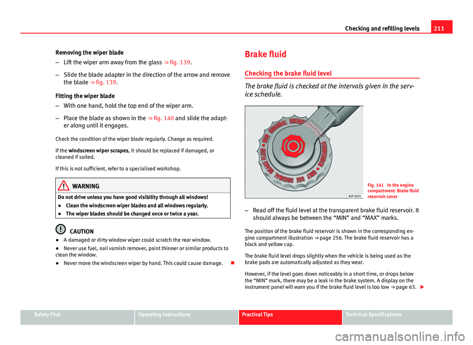
Fig. 141 In the engine
compartment: Brake fluid
reservoir cover
– Read off the fluid level at the transparent brake fluid reservoir. It
should always be between the “MIN” and “MAX” marks.
The position of the brake fluid reservoir is shown in the corresponding en-
gine compartment illustration ⇒ page 256. The brake fluid reservoir has a
black and yellow cap.
The brake fluid level drops slightly when the vehicle is being used as the
brake pads are automatically adjusted as they wear.
However, if the level goes down noticeably in a short time, or drops below
the “MIN” mark, there may be a leak in the brake system. A display on the
instrument panel will warn you if the brake fluid level is too low ⇒ page 63.
Safety FirstOperating InstructionsPractical TipsTechnical Specifications
Page 214 of 280
212Checking and refilling levels
WARNING
Before opening the bonnet to check the brake fluid level, read and ob-
serve the warnings ⇒ page 199.
Changing the brake fluid
The Maintenance Programme indicates the brake fluid
change intervals. We recommend that you have the brake fluid changed by an Authorised
Service Centre.
Before opening the bonnet, please read and follow the warnings ⇒
in
Safety instructions on working in the engine compartment on page 199 in
section “Safety notes for working in the engine compartment”.
Brake fluid absorbs moisture. In the course of time, it will absorb water from
the ambient air. If the water content in the brake fluid is too high, the brake
system could corrode. This also considerably reduces the boiling point of
the brake fluid. Heavy use of the brakes may then cause a vapour lock
which could impair the braking effect.
It is important that you use only brake fluid compliant with US standard
FMVSS 116 DOT 4. We recommend the use of Genuine SEAT brake fluid.
WARNING
Brake fluid is poisonous. Old brake fluid impairs the braking effect.
● Before opening the bonnet to check the brake fluid level, read and ob-
serve the warnings ⇒ page 199.
WARNING (Continued)
● Brake fluid should be stored in the closed original container in a safe
place out of reach of children. There is a toxic risk.
● Complete the brake fluid change according to the Maintenance Pro-
gramme. Heavy use of the brakes may cause a vapour lock if the brake
fluid is left in the system for too long. This would seriously affect the effi-
ciency of the brakes and the safety of the vehicle. This may cause an ac-
cident.
CAUTION
Brake fluid could damage the paintwork. Wipe off any brake fluid from the
paintwork immediately.
For the sake of the environment
The brake pads and fluid must be collected and disposed of according the
applicable regulations. The SEAT Technical Service network has the neces-
sary equipment and qualified personnel for collecting and disposing of this
waste material.
Page 216 of 280
214Checking and refilling levels
CAUTION
● Never disconnect the battery if the ignition is switched on or if the en-
gine is running. This could damage the electrical system or electronic com-
ponents.
● Do not expose the battery to direct sunlight over a long period of time,
as the intense ultraviolet radiation can damage the battery housing.
● If the vehicle is left standing in cold conditions for a long period, protect
the battery from freezing. If it freezes it will be damaged.
Checking the electrolyte level
The electrolyte level should be checked regularly in high-
mileage vehicles, in hot countries and in older batteries. – Open the engine bonnet and the battery cover ⇒
in Safety in-
structions on working in the engine compartment on page 200
⇒
in Warnings on handling the battery on page 213.
– Check the colour display in the "magic eye" on the top of the
battery.
– If there are air bubbles in the window, tap the window gently
until they disperse.
The position of the battery is shown in the corresponding engine compart-
ment diagram ⇒ page 256.
The “magic eye” indicator, located on the top of the battery changes colour,
depending on the charge state and electrolyte level of the battery.
There are two different colours: ●
Black: correct charge status.
● Transparent/clear yellow: the battery must be replaced. Contact a spe-
cialist workshop.
Charging and changing the vehicle battery
The battery is maintenance-free and is checked during the
inspection service. All work on the vehicle battery requires
specialist knowledge.
If you often drive short distances or if the vehicle is not driven for long peri-
ods, the battery should be checked by a specialised workshop between the
scheduled services.
If the battery has discharged and you have problems starting the vehicle,
the battery might be damaged. If this happens, we recommend you have
the vehicle battery checked by an Authorised Service Centre where it will be
re-charged or replaced.
Charging the battery
The vehicle battery should be charged by a specialised workshop only, as
batteries using special technology have been installed and they must be
charged in a controlled environment.
Replacing a vehicle battery
The battery has been developed to suit the conditions of its location and
has special safety features.
Genuine SEAT batteries fulfil the maintenance, performance and safety
specifications of your vehicle.
Page 223 of 280
221
If and when
If and when
Vehicle tools, spare wheel
Vehicle Tools
The vehicle onboard tools are located under the floor panel
in the luggage compartment.
– Lift floor panel
– Take the on-board tools out of the vehicle.
The tool kit includes:
● Jack*
● Hook to remove integral* trim and screw caps.
● Box spanner for wheel bolts*
● Towing ring*
● Adapter for the anti-theft wheel bolts*
Some of the items listed are only provided in certain model versions, or are
optional extras.
WARNING
● The factory-supplied jack is only designed for changing wheels on
this model. On no account attempt to use it for lifting heavier vehicles or
other loads. Risk of injury.
● Use the jack only on a firm, level ground.
WARNING (Continued)
● Never start the engine when the vehicle is on the jack. Risk of acci-
dent.
● If work is to be carried out underneath the vehicle, this must be se-
cured by suitable means. Otherwise, there is a risk of injury.
Spare wheel (emergency wheel)*
The spare wheel (emergency wheel) must only be used for
the minimum necessary time. The temporary spare wheel is stored under the floor panel in the luggage
compartment and is attached by a thumbnut.
How to use the temporary spare wheel
If you ever have a punctured tyre or loss of pressure, the emergency wheel
is only intended for temporary use until you reach a workshop. Change it for
a duty wheel as soon as possible.
Please note the following restrictions when using the temporary spare
wheel. This spare wheel has been specially designed for your vehicle, thus,
it cannot be changed with the spare wheel from another vehicle.
No other type of tyre (normal summer or winter tyre) may be fitted on the
compact temporary spare wheel rim.
Snow chains
For technical reasons, snow chains must not be used on the compact tem-
porary spare wheel.
Safety FirstOperating InstructionsPractical TipsTechnical Specifications
Page 224 of 280
222If and when
If you have a puncture on one of the front wheels when using snow chains,
fit the compact temporary spare in place of one of the rear wheels. You can
then attach the snow chains to the wheel taken from the rear and use this
wheel to replace the punctured front wheel.
WARNING
● The tyre pressures must be checked and corrected as soon as possi-
ble.
● Do not drive faster than 80 km/h. Higher speeds can cause an acci-
dent.
● Avoid heavy acceleration, hard braking and fast cornering. Risk of ac-
cident.
● Never use two or more compact spare tyres at the same time, risk of
accident.
● No other type of tyre (normal summer or winter tyre) may be fitted on
the compact temporary spare wheel rim.
Tyre repair kit*
The tyre repair kit (for vehicles not including a spare wheel)
is stored under the floor panel in the luggage compartment. Your vehicle is equipped with the Tyre Mobility System “Tyre repair kit”.
The tyre repair kit consists of a container with sealing compound to repair
the puncture and a compressor to generate the required tyre pressure. The
kit will reliably seal punctures up to a size of about 4 mm caused by the
penetration of a foreign body into the tyre.
Note
● Seek professional assistance if the repair of a tyre puncture is not possi-
ble with the sealing compound. Wheel change
Preparation work
What you must do before changing a wheel.
– If you have a flat tyre or puncture, park the vehicle as far away
from the flow of traffic as possible. Choose a location that is as
level as possible.
– All passengers should leave the vehicle. They should wait in a
safe area (for instance behind the roadside crash barrier).
– Switch the engine off. Switch the hazard warning lights on and
place the warning triangles in position.
– Apply the handbrake firmly.
– Engage the first gear , or put the selector lever to position P for
those vehicles with an automatic gearbox.
– If you are towing a trailer, unhitch it from your vehicle.
– Take the vehicle tools and the spare wheel out of the luggage
compartment.
WARNING
Switch on the hazard warning lights and place the warning triangles in
position. This is for your own safety and also warns other road users.
Page 232 of 280
230If and when
Note
● If a newly replaced fuse blows again after a short time, the electrical sys-
tem must be checked by a specialised workshop as soon as possible.
● If you replace a fuse with higher-rating fuse, you could cause damage to
another location in the electrical system.
● Always keep some spare fuses in the vehicle. These are available from
SEAT dealers.
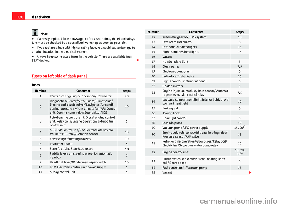
Fuses on left side of dash panel
Fuses
NumberConsumerAmps1Power steering/Engine operation/Flow meter7,5
2
Diagnostics/Heater/Autoclimate/Climatronic/
Electric anti-dazzle mirror/Navigator/Air condi-
tioning pressure switch/ Climate fan/AFS Control
unit/Coming home relay/Soundaktor/CCS
10
3Petrol engine control unit/Diesel engine control
unit/Relay coils/Engine operation/Bi-turbo fuel
control unit5
4ABS-ESP Control unit/RKA Switch/Gateway con-
trol unit/ESP Relay/Rotation sensor10
5Reverse light/Heating nozzles106Instrument panel57Retro fog light/Start-Stop relays7,5
8Paddle levers on steering wheel for automatic
gearbox2
9Headlight lever/Windscreen wiper switch1010BCM Electronic control unit power supply511Airbag control unit5
NumberConsumerAmps12Automatic gearbox/ LPG system1013Exterior mirror control514Left-hand AFS headlights1515Right-hand AFS headlights1516Vacant 17Number plate light518Clean pump7,519Electronic control unit520Indicators/Brake lights1521Lights control, instrument panel522Heated mirrors5
23Engine injection module/ Rain sensor/ Automat-
ic gear lever/ Main petrol relay7,5
24Luggage compartment light, interior light, glove
compartment light10
25Parking aid526Towing hook 27Headlight control528Lambda probe1029Vacuum pump/LPG power supply15, 20 a)
30Engine solenoid coils/Additional heating relay/
Pressure sensor/AKF Valve15
31Petrol engine operation/Glow plugs/Relay coil/
Electric fan/Secondary water pump relay10
32Engine control unit15, 20,
30 b)
33Clutch switch sensor/Additional heating relay
coil/ Servo sensor5
34Fuel control unit / Vacuum pump1535Vacant
Page 233 of 280
231
If and when
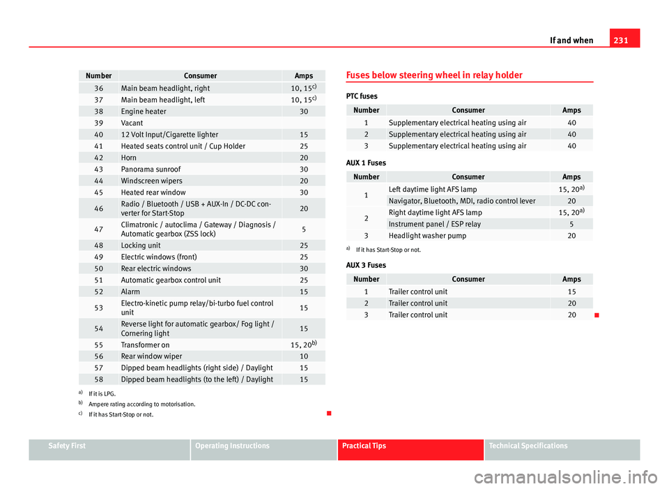
NumberConsumerAmps36Main beam headlight, right10, 15 c)37Main beam headlight, left10, 15c)38Engine heater3039Vacant 4012 Volt Input/Cigarette lighter1541Heated seats control unit / Cup Holder2542Horn2043Panorama sunroof3044Windscreen wipers2045Heated rear window30
46Radio / Bluetooth / USB + AUX-In / DC-DC con-
verter for Start-Stop20
47Climatronic / autoclima / Gateway / Diagnosis /
Automatic gearbox (ZSS lock)5
48Locking unit2549Electric windows (front)2550Rear electric windows3051Automatic gearbox control unit2552Alarm15
53Electro-kinetic pump relay/bi-turbo fuel control
unit15
54Reverse light for automatic gearbox/ Fog light /
Cornering light15
55Transformer on15, 20b)56Rear window wiper1057Dipped beam headlights (right side) / Daylight1558Dipped beam headlights (to the left) / Daylight15a)
If it is LPG.
b) Ampere rating according to motorisation.
c) If it has Start-Stop or not. Fuses below steering wheel in relay holder
PTC fuses
NumberConsumerAmps1Supplementary electrical heating using air402Supplementary electrical heating using air403Supplementary electrical heating using air40
AUX 1 Fuses
NumberConsumerAmps
1Left daytime light AFS lamp15, 20
a)Navigator, Bluetooth, MDI, radio control lever20
2Right daytime light AFS lamp15, 20a)Instrument panel / ESP relay53Headlight washer pump20a)
If it has Start-Stop or not.
AUX 3 Fuses
NumberConsumerAmps1Trailer control unit152Trailer control unit203Trailer control unit20
Safety FirstOperating InstructionsPractical TipsTechnical Specifications
Page 234 of 280

232If and when
Fuses in engine compartment above battery
Fig. 150 Fuses in engine
compartment
Non-metal fuses
NumberConsumerAmpsS1ABS ESP Control unit25S2Electroblower climate heater/fan30S3Automatic gearbox control unit30S4ABS ESP Control unit10S5Electronic control unit5S6Injection module30
Some of the electrical items listed in the table are only fitted on certain
models or are optional extras.
Please note that the above list contains all data at the time of going to
press, so it is subject to modifications. Bulb change
General notes
Before changing any bulb, first turn off the failed component.
Do not touch the bulb glass. Fingerprints vaporise in the heat, causing a re-
duction in the bulb life and condensation on the mirror surface, thus reduc-
ing efficiency.
A bulb should only be replaced by one of the same type. The type is inscri-
bed on the bulb, either on the glass part or on the base.
Below, the light source used for all functions is detailed.
Double headlights - H7 Long Life
- H7
- W5W Long Life - PY 21W
Single headlight - H4 Long Life
- W5W Long Life - PY 21W
Dipped beam
Main beam
Position
Turn signal
Dipped/Main
Position
Turn signal
Page 235 of 280
233
If and when
Xenon 1)
/ adaptive headlights*
- D1S2)
- LED 3)
- LED 3)
- PY 21W
Fog lights - H11
WARNING
● Take particular care when working on components in the engine com-
partment if the engine is warm - risk of burns!
● Bulbs are highly sensitive to pressure. The glass can break when you
touch the bulb, causing injury.
● The high voltage element of gas discharge bulbs* (xenon light) must
be handled correctly. Otherwise, there is a risk of death.
● When changing bulbs, please take care not to injure yourself on sharp
parts in the headlight housing.
CAUTION
● Remove the ignition key before working on the electric system. If not, a
short circuit could occur.
● Switch off the lights or parking lights before you change a bulb.
Dipped and full beam
Position
DRL (day light)
Turn signals
Fog light/cornering
For the sake of the environment
Please ask your specialist retailer how to dispose of used bulbs in the prop-
er manner.
Note
● Depending on weather conditions (cold or wet), the front lights, the fog
lights, the tail lights and the turn signals may be temporarily misted. This
has no influence on the useful life of the lighting system. By switching on
the lights, the area through which the beam of light is projected will quickly
be demisted. However, the edges may continue to be misted.
● Please check at regular intervals that all lighting (especially the exterior
lighting) on your vehicle is functioning properly. This is not only in the inter-
est of your own safety, but also that of all other road users.
● Before changing a bulb, make sure you have the correct new bulb.
● Do not touch the glass part of the bulb with your bare hands, use a cloth
or paper towel instead. Otherwise, the fingerprints left on the glass will va-
porise as a result of the heat generated by the bulb, they will be deposited
on the reflector and will impair its surface.
1)
With these types of headlights, the user can replace the turn signal bulb. Replacement of
the dipped/main beam bulb must be done by a Technical Service, given that complex ele-
ments must be removed from the vehicle and the automatic control system that incorpo-
rates it must be reset.
2) The Xenon bulbs discharge 2.5 times the light flux and have an average lifespan of 5 times
more than that of halogen bulbs, this means that, except due to unusual circumstances,
there is no need to change the bulbs for the whole life of the vehicle.
3) In the event that there is a fault in the LEDs, the complete headlight must be replaced.
Safety FirstOperating InstructionsPractical TipsTechnical Specifications