warning Seat Ibiza ST 2012 Owners Manual
[x] Cancel search | Manufacturer: SEAT, Model Year: 2012, Model line: Ibiza ST, Model: Seat Ibiza ST 2012Pages: 282, PDF Size: 3.77 MB
Page 128 of 282
126Seats and storage compartments
Cigarette lighter*
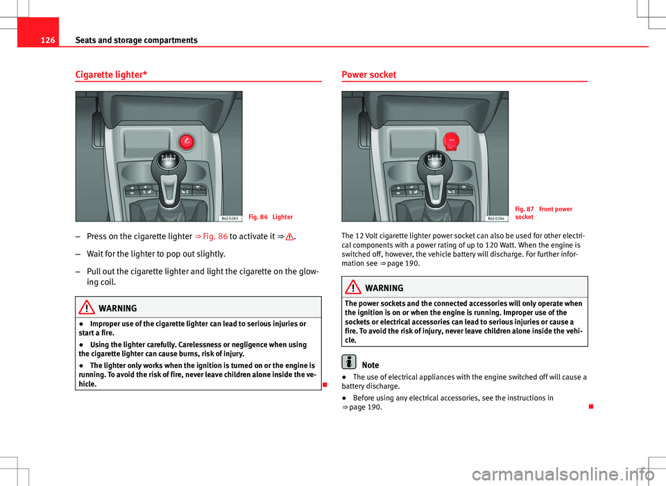
Fig. 86 Lighter
– Press on the cigarette lighter ⇒ Fig. 86 to activate it ⇒
.
– Wait for the lighter to pop out slightly.
– Pull out the cigarette lighter and light the cigarette on the glow-
ing coil.
WARNING
● Improper use of the cigarette lighter can lead to serious injuries or
start a fire.
● Using the lighter carefully. Carelessness or negligence when using
the cigarette lighter can cause burns, risk of injury.
● The lighter only works when the ignition is turned on or the engine is
running. To avoid the risk of fire, never leave children alone inside the ve-
hicle.
Power socket
Fig. 87 Front power
socket
The 12 Volt cigarette lighter power socket can also be used for other electri-
cal components with a power rating of up to 120 Watt. When the engine is
switched off, however, the vehicle battery will discharge. For further infor-
mation see ⇒ page 190.
WARNING
The power sockets and the connected accessories will only operate when
the ignition is on or when the engine is running. Improper use of the
sockets or electrical accessories can lead to serious injuries or cause a
fire. To avoid the risk of injury, never leave children alone inside the vehi-
cle.
Note
● The use of electrical appliances with the engine switched off will cause a
battery discharge.
● Before using any electrical accessories, see the instructions in
⇒ page 190.
Page 130 of 282
128Seats and storage compartments
For information concerning the use of this equipment, please see the Radio
handbook.
First-aid kit, warning triangle, fire
extinguisher Warning triangle*
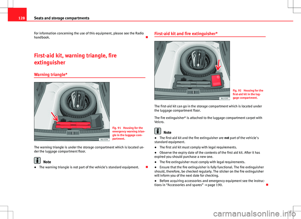
Fig. 91 Housing for the
emergency warning trian-
gle in the luggage com-
partment.
The warning triangle is under the storage compartment which is located un-
der the luggage compartment floor.
Note
● The warning triangle is not part of the vehicle's standard equipment. First-aid kit and fire extinguisher*
Fig. 92 Housing for the
first-aid kit in the lug-
gage compartment.
The first-aid kit can go in the storage compartment which is located under
the luggage compartment floor.
The fire extinguisher* is attached to the luggage compartment carpet with
Velcro.
Note
● The first-aid kit and the fire extinguisher are not part of the vehicle's
standard equipment.
● The first aid kit must comply with legal requirements.
● Observe the expiry date of the contents of the first aid kit. After it has
expired you should purchase a new one.
● The fire extinguisher must comply with legal requirements.
● Ensure that the fire extinguisher is fully functional. The fire extinguisher
should, therefore, be checked regularly. The sticker on the fire extinguisher
will inform you of the next date for checking.
● Before acquiring accessories and emergency equipment see the instruc-
tions in “Accessories and spares” ⇒ page 190.
Page 131 of 282
129
Seats and storage compartments
Luggage compartment
Loading the luggage compartment
Loads in the luggage compartment should be safely se-
cured.
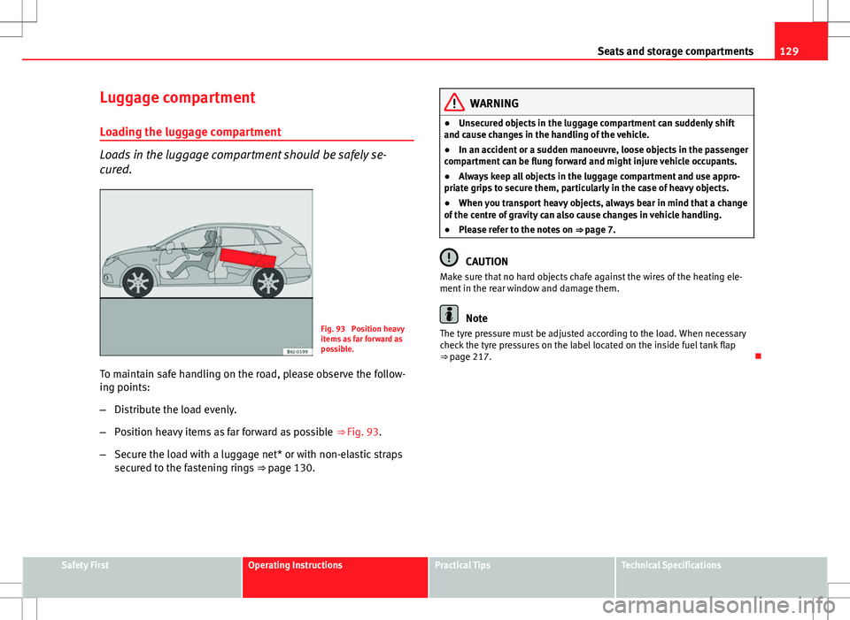
Fig. 93 Position heavy
items as far forward as
possible.
To maintain safe handling on the road, please observe the follow-
ing points:
– Distribute the load evenly.
– Position heavy items as far forward as possible ⇒ Fig. 93.
– Secure the load with a luggage net* or with non-elastic straps
secured to the fastening rings ⇒ page 130.
WARNING
● Unsecured objects in the luggage compartment can suddenly shift
and cause changes in the handling of the vehicle.
● In an accident or a sudden manoeuvre, loose objects in the passenger
compartment can be flung forward and might injure vehicle occupants.
● Always keep all objects in the luggage compartment and use appro-
priate grips to secure them, particularly in the case of heavy objects.
● When you transport heavy objects, always bear in mind that a change
of the centre of gravity can also cause changes in vehicle handling.
● Please refer to the notes on ⇒ page 7.
CAUTION
Make sure that no hard objects chafe against the wires of the heating ele-
ment in the rear window and damage them.
Note
The tyre pressure must be adjusted according to the load. When necessary
check the tyre pressures on the label located on the inside fuel tank flap
⇒ page 217.
Safety FirstOperating InstructionsPractical TipsTechnical Specifications
Page 132 of 282
130Seats and storage compartments
Fastening rings*
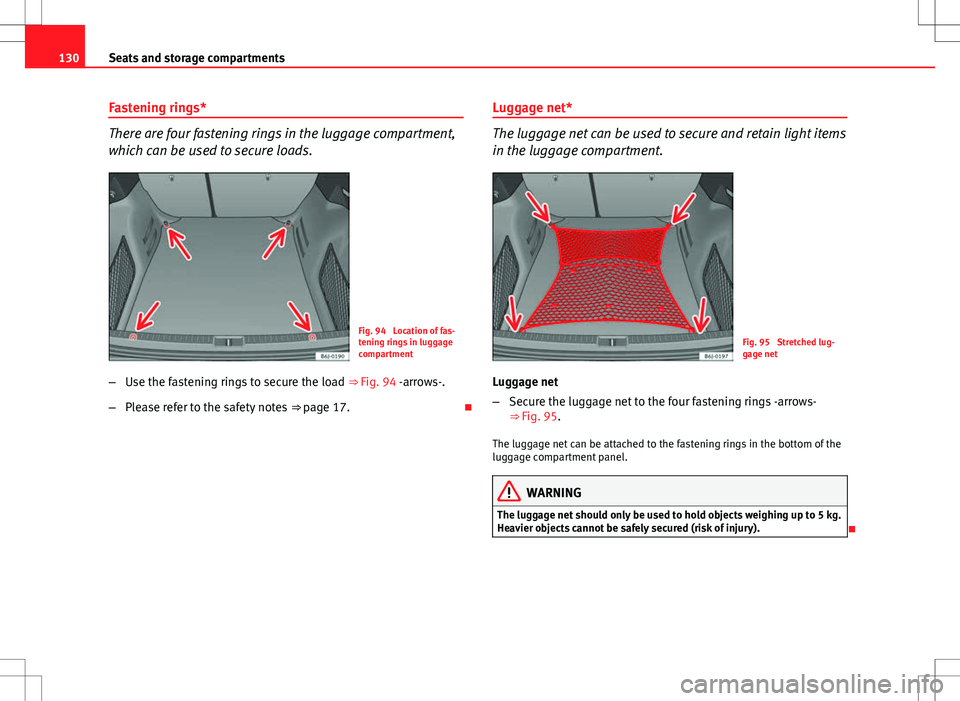
There are four fastening rings in the luggage compartment,
which can be used to secure loads.
Fig. 94 Location of fas-
tening rings in luggage
compartment
– Use the fastening rings to secure the load ⇒ Fig. 94 -arrows-.
– Please refer to the safety notes ⇒ page 17. Luggage net*
The luggage net can be used to secure and retain light items
in the luggage compartment.
Fig. 95 Stretched lug-
gage net
Luggage net
– Secure the luggage net to the four fastening rings -arrows-
⇒ Fig. 95.
The luggage net can be attached to the fastening rings in the bottom of the
luggage compartment panel.
WARNING
The luggage net should only be used to hold objects weighing up to 5 kg.
Heavier objects cannot be safely secured (risk of injury).
Page 133 of 282
131
Seats and storage compartments
Rear shelf
Fig. 96 Rear shelf
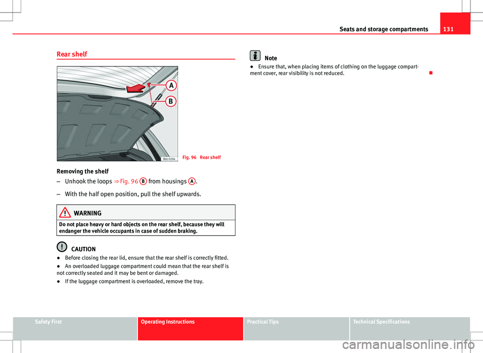
Removing the shelf
– Unhook the loops ⇒ Fig. 96 B
from housings A.
– With the half open position, pull the shelf upwards.
WARNING
Do not place heavy or hard objects on the rear shelf, because they will
endanger the vehicle occupants in case of sudden braking.
CAUTION
● Before closing the rear lid, ensure that the rear shelf is correctly fitted.
● An overloaded luggage compartment could mean that the rear shelf is
not correctly seated and it may be bent or damaged.
● If the luggage compartment is overloaded, remove the tray.
Note
● Ensure that, when placing items of clothing on the luggage compart-
ment cover, rear visibility is not reduced.
Safety FirstOperating InstructionsPractical TipsTechnical Specifications
Page 134 of 282
132Seats and storage compartments
Rear shelf with storage compartment*
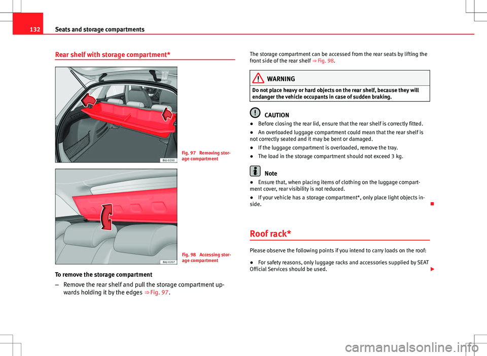
Fig. 97 Removing stor-
age compartment
Fig. 98 Accessing stor-
age compartment
To remove the storage compartment
– Remove the rear shelf and pull the storage compartment up-
wards holding it by the edges ⇒ Fig. 97. The storage compartment can be accessed from the rear seats by lifting the
front side of the rear shelf
⇒ Fig. 98.
WARNING
Do not place heavy or hard objects on the rear shelf, because they will
endanger the vehicle occupants in case of sudden braking.
CAUTION
● Before closing the rear lid, ensure that the rear shelf is correctly fitted.
● An overloaded luggage compartment could mean that the rear shelf is
not correctly seated and it may be bent or damaged.
● If the luggage compartment is overloaded, remove the tray.
● The load in the storage compartment should not exceed 3 kg.
Note
● Ensure that, when placing items of clothing on the luggage compart-
ment cover, rear visibility is not reduced.
● If your vehicle has a storage compartment*, only place light objects in-
side.
Roof rack*
Please observe the following points if you intend to carry loads on the roof:
● For safety reasons, only luggage racks and accessories supplied by SEAT
Official Services should be used.
Page 136 of 282
134Air conditioning
Air conditioning
Heating
Controls
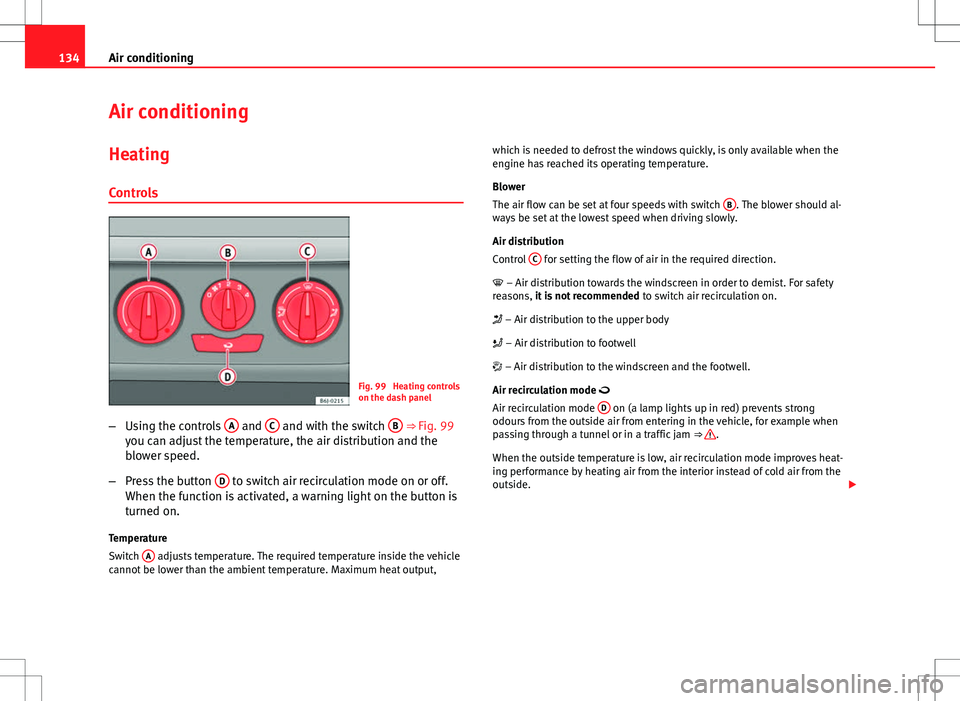
Fig. 99 Heating controls
on the dash panel
– Using the controls A
and C and with the switch B ⇒ Fig. 99
you can adjust the temperature, the air distribution and the
blower speed.
– Press the button D
to switch air recirculation mode on or off.
When the function is activated, a warning light on the button is
turned on.
Temperature
Switch A
adjusts temperature. The required temperature inside the vehicle
cannot be lower than the ambient temperature. Maximum heat output, which is needed to defrost the windows quickly, is only available when the
engine has reached its operating temperature.
Blower
The air flow can be set at four speeds with switch
B
. The blower should al-
ways be set at the lowest speed when driving slowly.
Air distribution
Control C
for setting the flow of air in the required direction.
– Air distribution towards the windscreen in order to demist. For safety
reasons, it is not recommended to switch air recirculation on.
– Air distribution to the upper body
– Air distribution to footwell
– Air distribution to the windscreen and the footwell.
Air recirculation mode
Air recirculation mode D
on (a lamp lights up in red) prevents strong
odours from the outside air from entering in the vehicle, for example when
passing through a tunnel or in a traffic jam ⇒
.
When the outside temperature is low, air recirculation mode improves heat-
ing performance by heating air from the interior instead of cold air from the
outside.
Page 137 of 282
135
Air conditioning
WARNING
● For your safety, the windows should never be fogged up or covered
with snow or ice. This is essential to ensure good visibility. Please famili-
arise yourself with the correct operation of the heating and ventilation
system, including the demist/defrost functions for the windows.
● In air recirculation mode, no cold air from the outside enters the vehi-
cle interior. The windows can quickly fog over if the heating is switched
off. Therefore, never leave the air recirculation mode switched on for a
long time (risk of accident).
Note
● Please consider the general notes ⇒ page 142.
Vehicle ventilation or heating
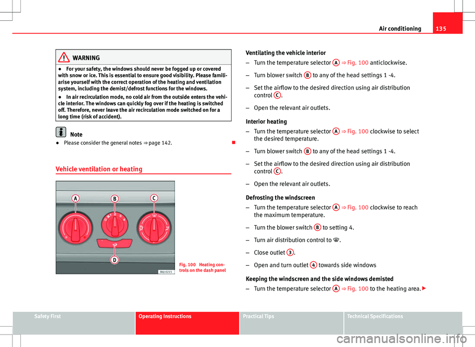
Fig. 100 Heating con-
trols on the dash panel Ventilating the vehicle interior
–
Turn the temperature selector A
⇒ Fig. 100 anticlockwise.
– Turn blower switch B
to any of the head settings 1 -4.
– Set the airflow to the desired direction using air distribution
control C
.
– Open the relevant air outlets.
Interior heating
– Turn the temperature selector A
⇒ Fig. 100 clockwise to select
the desired temperature.
– Turn blower switch B
to any of the head settings 1 -4.
– Set the airflow to the desired direction using air distribution
control C
.
– Open the relevant air outlets.
Defrosting the windscreen
– Turn the temperature selector A
⇒ Fig. 100 clockwise to reach
the maximum temperature.
– Turn the blower switch B
to setting 4.
– Turn air distribution control to .
– Close outlet 3
.
– Open and turn outlet 4
towards side windows
Keeping the windscreen and the side windows demisted
– Turn the temperature selector A
⇒ Fig. 100 to the heating area.
Safety FirstOperating InstructionsPractical TipsTechnical Specifications
Page 139 of 282
137
Air conditioning
Air distribution C
Switch on symbolMain air output through outlets:
1,2
5
1, 2, 5
3, 4
Outlets 3 and 4 can be closed or opened separately and the air flow di-
rected as required.
Air conditioning* Controls
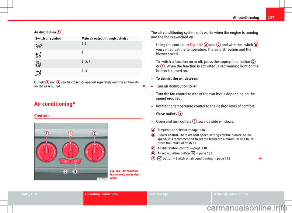
Fig. 102 Air condition-
ing controls on the dash
panel The air conditioning system only works when the engine is running
and the fan is switched on.
–
Using the controls ⇒ Fig. 102 A
and C and with the switch Byou can adjust the temperature, the air distribution and the
blower speed.
– To switch a function on or off, press the appropriate button D
or E. When the function is activated, a red warning light on the
button is turned on.
– To demist the windscreen:
– Turn air distribution to .
– Turn the fan control to one of the two levels depending on the
speed required.
– Rotate the temperature control to the desired level of comfort.
– Close outlets 3
–
Open and turn outlets 4 towards side windows.
Temperature selector ⇒ page 138
Blower control. There are four speed settings for the blower. At low
speed, it is recommended to set the blower to a minimum of 1 to im-
prove the intake of fresh air.
Air distribution control ⇒ page 138
Air recirculation button
⇒ page 139
AC button – Switch on air conditioning ⇒ page 138
A
B
CDE
Safety FirstOperating InstructionsPractical TipsTechnical Specifications
Page 140 of 282
138Air conditioning
WARNING
For your safety, the windows should never be fogged up or covered with
snow or ice. This is essential to ensure good visibility. Please familiarise
yourself with the correct operation of the heating and ventilation system,
including the demist/defrost functions for the windows.
Note
Please consider the general notes.
Vehicle interior heating or cooling system
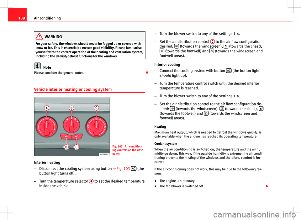
Fig. 103 Air condition-
ing controls on the dash
panel
Interior heating
– Disconnect the cooling system using button ⇒ Fig. 103 AC
(the
button light turns off).
– Turn the temperature selector A
to set the desired temperature
inside the vehicle. –
Turn the blower switch to any of the settings 1-4.
– Set the air distribution control C
to the air flow configuration
desired: (towards the windscreen), (towards the chest),
(towards the footwell) and (towards the windscreen and
footwell areas).
Interior cooling
– Connect the cooling system with button AC
(the button light
should light up).
– Turn the temperature control switch until the desired interior
temperature is reached.
– Turn the blower switch to any of the settings 1-4.
– Set the air distribution control to the air flow configuration de-
sired:
(towards the windscreen), (towards the chest), (towards the footwell) and (towards the windscreen and
footwell areas).
Heating
Maximum heat output, which is needed to defrost the windows quickly, is
only available when the engine has reached its operating temperature.
Coolant system
When the air conditioning is switched on, the temperature and the air hu-
midity go down. This way, if the outside humidity is extreme, the air condi-
tioning prevents the misting of the windows and therefore, comfort is im-
proved.
If the air conditioning does not work, this may be due to the following rea-
sons:
● The engine is stationary.
● The fan blower is switched off.