lock Seat Ibiza ST 2012 Repair Manual
[x] Cancel search | Manufacturer: SEAT, Model Year: 2012, Model line: Ibiza ST, Model: Seat Ibiza ST 2012Pages: 282, PDF Size: 3.77 MB
Page 215 of 282
213
Checking and refilling levels
Brake fluid Checking the brake fluid level
The brake fluid is checked at the intervals given in the serv-
ice schedule.
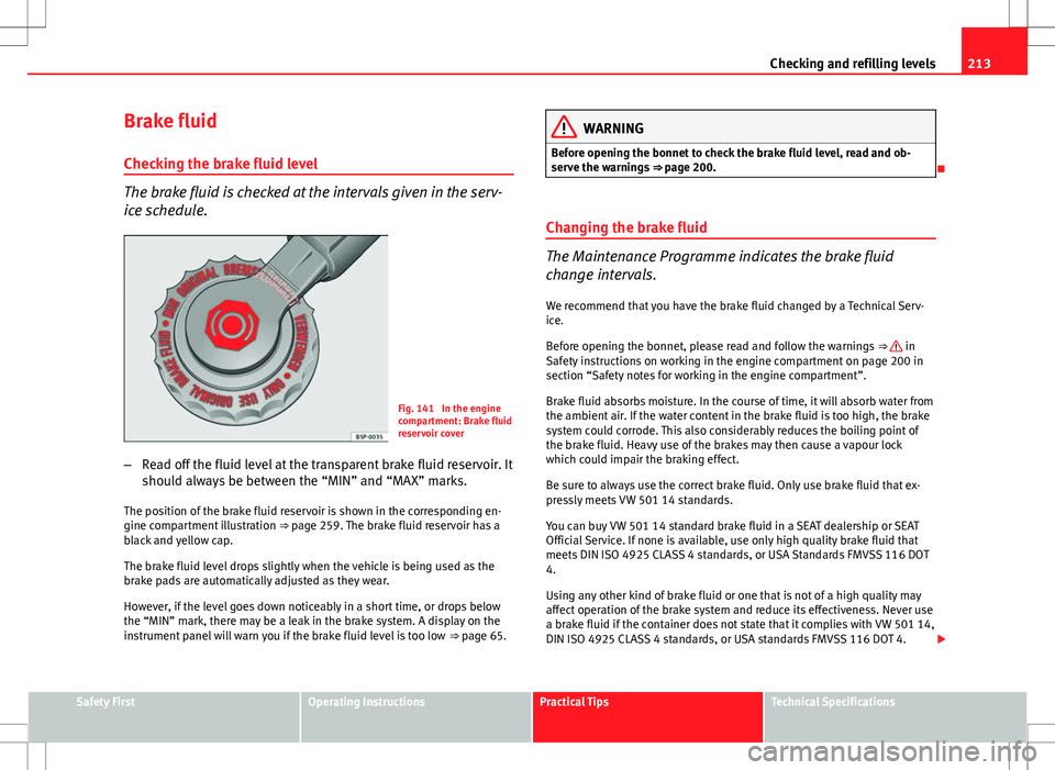
Fig. 141 In the engine
compartment: Brake fluid
reservoir cover
– Read off the fluid level at the transparent brake fluid reservoir. It
should always be between the “MIN” and “MAX” marks.
The position of the brake fluid reservoir is shown in the corresponding en-
gine compartment illustration ⇒ page 259. The brake fluid reservoir has a
black and yellow cap.
The brake fluid level drops slightly when the vehicle is being used as the
brake pads are automatically adjusted as they wear.
However, if the level goes down noticeably in a short time, or drops below
the “MIN” mark, there may be a leak in the brake system. A display on the
instrument panel will warn you if the brake fluid level is too low ⇒ page 65.
WARNING
Before opening the bonnet to check the brake fluid level, read and ob-
serve the warnings ⇒ page 200.
Changing the brake fluid
The Maintenance Programme indicates the brake fluid
change intervals. We recommend that you have the brake fluid changed by a Technical Serv-
ice.
Before opening the bonnet, please read and follow the warnings ⇒
in
Safety instructions on working in the engine compartment on page 200 in
section “Safety notes for working in the engine compartment”.
Brake fluid absorbs moisture. In the course of time, it will absorb water from
the ambient air. If the water content in the brake fluid is too high, the brake
system could corrode. This also considerably reduces the boiling point of
the brake fluid. Heavy use of the brakes may then cause a vapour lock
which could impair the braking effect.
Be sure to always use the correct brake fluid. Only use brake fluid that ex-
pressly meets VW 501 14 standards.
You can buy VW 501 14 standard brake fluid in a SEAT dealership or SEAT
Official Service. If none is available, use only high quality brake fluid that
meets DIN ISO 4925 CLASS 4 standards, or USA Standards FMVSS 116 DOT
4.
Using any other kind of brake fluid or one that is not of a high quality may
affect operation of the brake system and reduce its effectiveness. Never use
a brake fluid if the container does not state that it complies with VW 501 14,
DIN ISO 4925 CLASS 4 standards, or USA standards FMVSS 116 DOT 4.
Safety FirstOperating InstructionsPractical TipsTechnical Specifications
Page 216 of 282
214Checking and refilling levels
WARNING
Brake fluid is poisonous. Old brake fluid impairs the braking effect.
● Before opening the bonnet to check the brake fluid level, read and ob-
serve the warnings ⇒ page 200.
● Brake fluid should be stored in the closed original container in a safe
place out of reach of children. There is a toxic risk.
● Complete the brake fluid change according to the Maintenance Pro-
gramme. Heavy use of the brakes may cause a vapour lock if the brake
fluid is left in the brake system for too long. This would seriously affect
the effectiveness of the brakes and the safety of the vehicle. This may
cause an accident.
CAUTION
Brake fluid damages the vehicle paintwork. Wipe off any brake fluid from
the paintwork immediately.
For the sake of the environment
The brake pads and brake fluid must be collected and disposed of accord-
ing the applicable regulations. The SEAT Technical Service network has the
necessary equipment and qualified personnel for collecting and disposing
of this waste material. Vehicle battery
Warnings on handling the battery
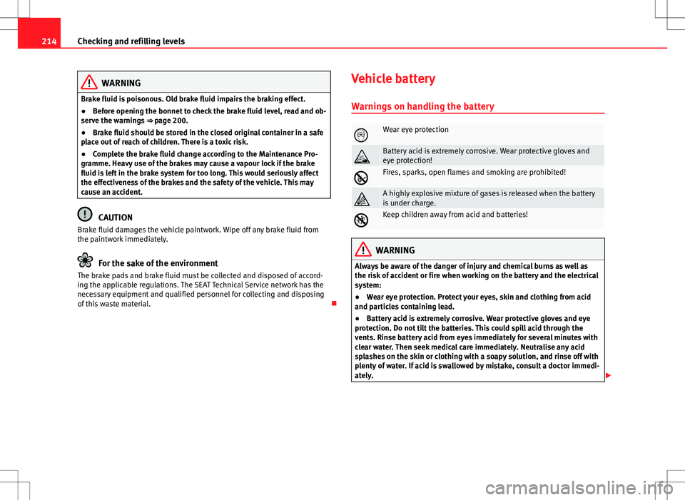
Wear eye protection
Battery acid is extremely corrosive. Wear protective gloves and
eye protection!
Fires, sparks, open flames and smoking are prohibited!
A highly explosive mixture of gases is released when the battery
is under charge.
Keep children away from acid and batteries!
WARNING
Always be aware of the danger of injury and chemical burns as well as
the risk of accident or fire when working on the battery and the electrical
system:
● Wear eye protection. Protect your eyes, skin and clothing from acid
and particles containing lead.
● Battery acid is extremely corrosive. Wear protective gloves and eye
protection. Do not tilt the batteries. This could spill acid through the
vents. Rinse battery acid from eyes immediately for several minutes with
clear water. Then seek medical care immediately. Neutralise any acid
splashes on the skin or clothing with a soapy solution, and rinse off with
plenty of water. If acid is swallowed by mistake, consult a doctor immedi-
ately.
Page 217 of 282
215
Checking and refilling levels
WARNING (Continued)
● Fires, sparks, open flames and smoking are prohibited. When han-
dling cables and electrical equipment, avoid causing sparks and electro-
static charge. Never short the battery terminals. High-energy sparks can
cause injury.
● A highly explosive mixture of gases is released when the battery is
under charge. The batteries should be charged in a well-ventilated room
only.
● Keep children away from acid and batteries.
● Before working on the electrical system, you must switch off the en-
gine, the ignition and all consumers. The negative cable on the battery
must be disconnected. When a light bulb is changed, you need only
switch off the light.
● Deactivate the anti-theft alarm by unlocking the vehicle before you
disconnect the battery! The alarm will otherwise be triggered.
● When disconnecting the battery from the vehicle on-board network,
disconnect first the negative cable and then the positive cable.
● Switch off all electrical consumers before reconnecting the battery.
Reconnect first the positive cable and then the negative cable. Never re-
verse the polarity of the connections. This could cause an electrical fire.
● Never charge a frozen battery, or one which has thawed. This could
result in explosions and chemical burns. Always replace a battery which
has frozen. A flat battery can freeze at temperatures around 0°C.
● Ensure that the vent hose is always connected to the battery.
● Never use a defective battery. This could cause an explosion. Replace
a damaged battery immediately.
● For vehicles with the battery in the luggage compartment: Check that
the battery gas ventilation hose is securely attached.CAUTION
● Never disconnect the battery if the ignition is switched on or if the en-
gine is running. This could damage the electrical system or electronic com-
ponents.
● Do not expose the battery to direct sunlight over a long period of time,
as the intense ultraviolet radiation can damage the battery housing.
● If the vehicle is left standing in cold conditions for a long period, protect
the battery from freezing. If it freezes it will be damaged.
Checking the electrolyte level
The electrolyte level should be checked regularly in high-
mileage vehicles, in hot countries and in older batteries. – Open the engine bonnet and the battery cover ⇒
in Safety in-
structions on working in the engine compartment on page 201
⇒
in Warnings on handling the battery on page 214.
– Check the colour display in the "magic eye" on the top of the
battery.
– If there are air bubbles in the window, tap the window gently
until they disperse.
The position of the battery is shown in the corresponding engine compart-
ment diagram ⇒ page 259.
The “magic eye” indicator, located on the top of the battery changes colour,
depending on the charge state and electrolyte level of the battery.
There are two different colours:
Safety FirstOperating InstructionsPractical TipsTechnical Specifications
Page 227 of 282
225
If and when
WARNING
Switch on the hazard warning lights and place the warning triangles in
position. This is for your own safety and also warns other road users.
CAUTION
If you have to change the wheel on a slope, it is essential to lock the parallel
wheel on the same axle as that to be changed, with a wedge or similar in
order to immobilise the vehicle.
Note
Please observe legal requirements when doing so.
Changing a wheel
Change the wheel as described below
– Remove the hub caps or the integral trim .
– Slacken the wheel bolts .
– Raise the vehicle with the jack at the corresponding point.
– Remove the wheel and then fit the spare wheel.
– Lower the vehicle.
– Tighten the wheel bolts firmly with the box spanner.
– Replace the hub cap. After changing a wheel
After changing the wheel there are still tasks to complete.
– Put the tools and jack back in the luggage compartment.
– Place the wheel with the defective tyre in the luggage compart-
ment and secure it.
– Check the tyre pressure of the newly fitted tyre as soon as pos-
sible.
– Have the tightening torque of the wheel bolts checked as soon
as possible with a torque wrench. The prescribed torque must
be 120 Nm.
Note
● If you notice that the wheel bolts are corroded and difficult to turn when
changing a wheel, they must be replaced before having the wheel bolt tight-
ening torque checked.
● For safety reasons, drive at moderate speeds until the wheel bolt tight-
ening torque has been checked.
Safety FirstOperating InstructionsPractical TipsTechnical Specifications
Page 235 of 282
233
If and when
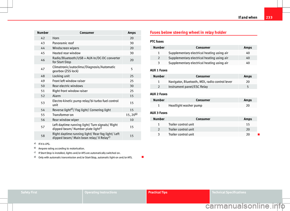
NumberConsumerAmps42Horn2043Panoramic roof3044Windscreen wipers2045Heated rear window30
46Radio/Bluetooth/USB + AUX-In/DC-DC converter
for Start-Stop20
47Climatronic/autoclima/Diagnosis/Automatic
gearbox (ZSS lock)5
48Locking unit2549Front left window raiser2550Rear electric windows3051Right front window raiser2552Alarm15
53Electro-kinetic pump relay/bi-turbo fuel control
unit15
54Reverse light d)
/ Fog light/ Cornering light1555Transformer on15, 20 b)56Rear window wiper10
57Left daytime running light/ Turn signals/ Right
dipped beam/ Number plate light c)15
58Right daytime running light/ Rear fog light/ Left
dipped beam/ Main bean relay/ X Relay c)15
a)
If it is LPG.
b) Ampere rating according to motorisation.
c) If Start-Stop is installed, lights and/or AFS are automatically switched on.
d) Only with automatic transmission and/or Start-Stop, automatic light-on and/or AFS. Fuses below steering wheel in relay holder
PTC fuses
NumberConsumerAmps1Supplementary electrical heating using air402Supplementary electrical heating using air403Supplementary electrical heating using air40
AUX 1 Fuses
NumberConsumerAmps1Navigator, Bluetooth, MDI, radio control lever202Instrument panel/ESC Relay5
AUX 2 Fuses
NumberConsumerAmps1Headlight washer pump20
AUX 3 Fuses
NumberConsumerAmps1Trailer control unit152Trailer control unit203Trailer control unit20
Safety FirstOperating InstructionsPractical TipsTechnical Specifications
Page 245 of 282
243
If and when
Changing the fog light bulbs
Fog light bulb
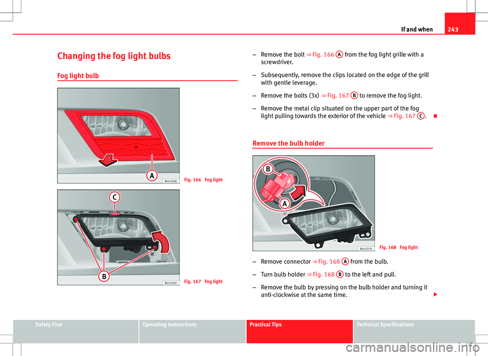
Fig. 166 Fog light
Fig. 167 Fog light –
Remove the bolt ⇒ Fig. 166 A
from the fog light grille with a
screwdriver.
– Subsequently, remove the clips located on the edge of the grill
with gentle leverage.
– Remove the bolts (3x) ⇒ Fig. 167 B
to remove the fog light.
– Remove the metal clip situated on the upper part of the fog
light pulling towards the exterior of the vehicle ⇒ Fig. 167 C
.
Remove the bulb holder
Fig. 168 Fog light
– Remove connector ⇒ Fig. 168 A
from the bulb.
– Turn bulb holder ⇒ Fig. 168 B
to the left and pull.
– Remove the bulb by pressing on the bulb holder and turning it
anti-clockwise at the same time.
Safety FirstOperating InstructionsPractical TipsTechnical Specifications
Page 251 of 282
249
If and when
Jump leads
Jump leads must comply with standard DIN 72553 (see cable manufactur-
er's instructions). The wire cross section must be at least 25 mm 2
for petrol
engines and at least 35 mm 2
for diesel engines.
Note
● The vehicles must not touch each other, otherwise electricity could flow
as soon as the positive terminals are connected.
● The discharged battery must be properly connected to the on-board net-
work.
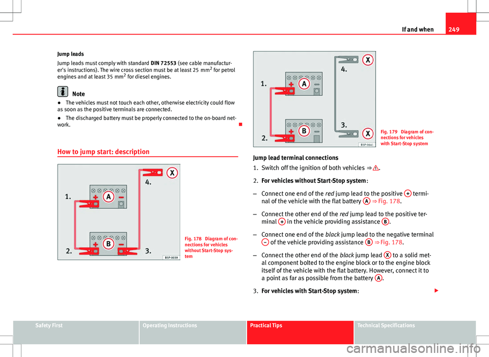
How to jump start: description
Fig. 178 Diagram of con-
nections for vehicles
without Start-Stop sys-
tem
Fig. 179 Diagram of con-
nections for vehicles
with Start-Stop system
Jump lead terminal connections
1. Switch off the ignition of both vehicles ⇒
.
2. For vehicles without Start-Stop system :
– Connect one end of the red jump lead to the positive +
termi-
nal of the vehicle with the flat battery A ⇒ Fig. 178.
– Connect the other end of the red jump lead to the positive ter-
minal +
in the vehicle providing assistance B.
– Connect one end of the black jump lead to the negative terminal
–
of the vehicle providing assistance B ⇒ Fig. 178.
– Connect the other end of the black jump lead X
to a solid met-
al component bolted to the engine block or to the engine block
itself of the vehicle with the flat battery. However, connect it to
a point as far as possible from the battery A
.
3. For vehicles with Start-Stop system :
Safety FirstOperating InstructionsPractical TipsTechnical Specifications
Page 252 of 282
250If and when
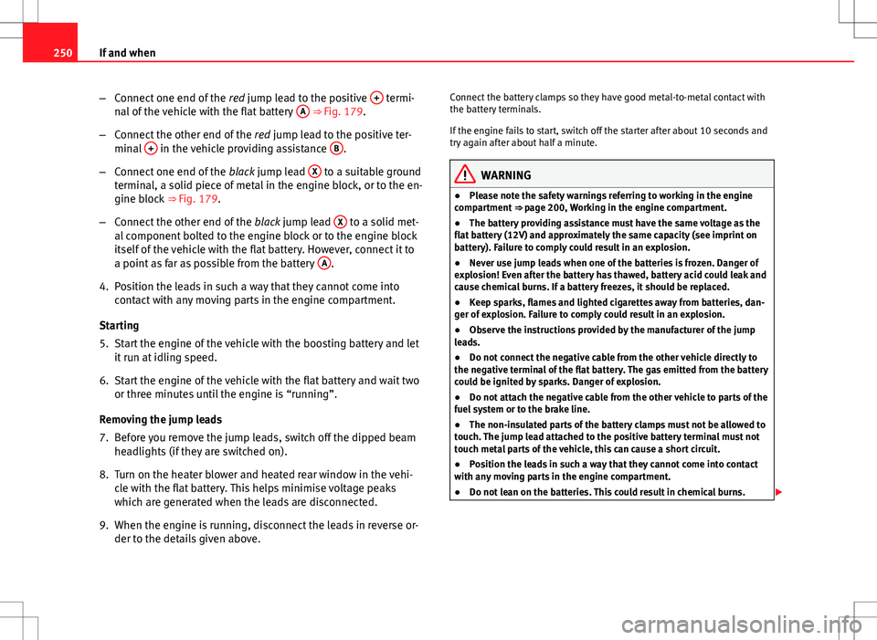
–Connect one end of the red jump lead to the positive +
termi-
nal of the vehicle with the flat battery A ⇒ Fig. 179.
– Connect the other end of the red jump lead to the positive ter-
minal +
in the vehicle providing assistance B.
– Connect one end of the black jump lead X
to a suitable ground
terminal, a solid piece of metal in the engine block, or to the en-
gine block ⇒ Fig. 179.
– Connect the other end of the black jump lead X
to a solid met-
al component bolted to the engine block or to the engine block
itself of the vehicle with the flat battery. However, connect it to
a point as far as possible from the battery A
.
4. Position the leads in such a way that they cannot come into contact with any moving parts in the engine compartment.
Starting
5. Start the engine of the vehicle with the boosting battery and let it run at idling speed.
6. Start the engine of the vehicle with the flat battery and wait two or three minutes until the engine is “running”.
Removing the jump leads
7. Before you remove the jump leads, switch off the dipped beam headlights (if they are switched on).
8. Turn on the heater blower and heated rear window in the vehi- cle with the flat battery. This helps minimise voltage peaks
which are generated when the leads are disconnected.
9. When the engine is running, disconnect the leads in reverse or- der to the details given above. Connect the battery clamps so they have good metal-to-metal contact with
the battery terminals.
If the engine fails to start, switch off the starter after about 10 seconds and
try again after about half a minute.
WARNING
● Please note the safety warnings referring to working in the engine
compartment ⇒ page 200, Working in the engine compartment.
● The battery providing assistance must have the same voltage as the
flat battery (12V) and approximately the same capacity (see imprint on
battery). Failure to comply could result in an explosion.
● Never use jump leads when one of the batteries is frozen. Danger of
explosion! Even after the battery has thawed, battery acid could leak and
cause chemical burns. If a battery freezes, it should be replaced.
● Keep sparks, flames and lighted cigarettes away from batteries, dan-
ger of explosion. Failure to comply could result in an explosion.
● Observe the instructions provided by the manufacturer of the jump
leads.
● Do not connect the negative cable from the other vehicle directly to
the negative terminal of the flat battery. The gas emitted from the battery
could be ignited by sparks. Danger of explosion.
● Do not attach the negative cable from the other vehicle to parts of the
fuel system or to the brake line.
● The non-insulated parts of the battery clamps must not be allowed to
touch. The jump lead attached to the positive battery terminal must not
touch metal parts of the vehicle, this can cause a short circuit.
● Position the leads in such a way that they cannot come into contact
with any moving parts in the engine compartment.
● Do not lean on the batteries. This could result in chemical burns.
Page 255 of 282
253
If and when
Do not pull too hard with the towing vehicle and take care to avoid jerking
the tow rope. When towing on an unpaved road, there is always a risk of
overloading and damaging the anchorage points.
The ignition of the vehicle being towed must be switched on to prevent the
steering wheel from locking and also to allow the use of the turn signals,
horn, windscreen wipers and washers.
As the brake servo does not work if the engine is not running, you must ap-
ply considerably more pressure to the brake pedal than you normally would.
As the power assisted steering does not work if the engine is not running,
you will need more strength to steer than you normally would.
Towing vehicles with an automatic gearbox
● Put the selector lever into position “N”.
● Do not drive faster than 50 km/h (30 mph).
● Do not tow further than 50 km (30 miles).
● If a breakdown vehicle is used, the vehicle must be towed with the front
wheels raised.
Note
● Observe legal requirements when towing or tow-starting.
● Switch on the hazard warning lights of both vehicles. However, observe
any regulations to the contrary.
● For technical reasons, vehicles with an automatic gearbox must not be
tow-started.
● If damage to your vehicle means that there is no lubricant in the gear-
box, you must raise the driven wheels while the vehicle is being towed.
● If the vehicle has to be towed more than 50 km (30 miles), the front
wheels should be raised during towing, and towing should be carried out by
a qualified person. ●
The steering wheel is locked when the vehicle has no electrical power.
The vehicle must then be towed with the front wheels raised. Towing should
be carried out by a qualified person.
● The towline anchorage should always be kept in the vehicle.
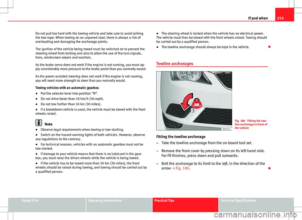
Towline anchoragesFig. 180 Fitting the tow-
line anchorage to front of
the vehicle
Fitting the towline anchorage
– Take the towline anchorage from the on-board tool set.
– Remove the front cover by pressing down on its left-hand side.
For FR finishes, press down and pull outwards.
– Bolt the anchorage to its limit to the left, in the direction of the
arrow ⇒ Fig. 180.
Safety FirstOperating InstructionsPractical TipsTechnical Specifications
Page 273 of 282
Index
A
ABS . . . . . . . . . . . . . . . . . . . . . . . . . . . . . . . . . . 169control lamp . . . . . . . . . . . . . . . . . . . . . . . . . 71
Accessories . . . . . . . . . . . . . . . . . . . . . . . . . . . . 190
Acoustic warning . . . . . . . . . . . . . . . . . . . . . . . 145
Adaptive headlights . . . . . . . . . . . . . . . . . . . . . 103
AFS headlight bulbs . . . . . . . . . . . . . . . . . . . . . 242
Airbag covers . . . . . . . . . . . . . . . . . . . . . . . . . . . 36
Airbag system . . . . . . . . . . . . . . . . . . . . . . . . . . . 30 control lamp . . . . . . . . . . . . . . . . . . . . . . . . . 31
Front airbags . . . . . . . . . . . . . . . . . . . . . . . . 34
side airbags . . . . . . . . . . . . . . . . . . . . . . . . . 38
Air conditioner Climatronic . . . . . . . . . . . . . . . . . . . . . . . . . 140
General notes . . . . . . . . . . . . . . . . . . . . . . . 142
Air conditioning* . . . . . . . . . . . . . . . . . . . . . . . 137
Air outlets . . . . . . . . . . . . . . . . . . . . . . . . . . . . . 136
Air recirculation Semi-automatic air conditioning . . . . . . . . 139
Air recirculation mode Climatronic . . . . . . . . . . . . . . . . . . . . . . . . . 142
Alarm system Switching off . . . . . . . . . . . . . . . . . . . . . . . . . 90
Alternator Warning lamp . . . . . . . . . . . . . . . . . . . . . . . . 76
Anti-lock brake system . . . . . . . . . . . . . . . . . . . 169 control lamp . . . . . . . . . . . . . . . . . . . . . . . . . 71 Anti-theft alarm system . . . . . . . . . . . . . . . . . . . 90
Switching off . . . . . . . . . . . . . . . . . . . . . . . . . 90
Anti-theft wheel bolts . . . . . . . . . . . . . . . . . . . 226
Antifreeze . . . . . . . . . . . . . . . . . . . . . . . . . . . . . 207
Aquaplaning . . . . . . . . . . . . . . . . . . . . . . . . . . . 219
Ashtray . . . . . . . . . . . . . . . . . . . . . . . . . . . . . . . 125
Aspects to note before setting off . . . . . . . . . . . . 8
ASR . . . . . . . . . . . . . . . . . . . . . . . . . . . . . . . . . . 169
ASR (Traction control system) Control lamp . . . . . . . . . . . . . . . . . . . . . . . . . 72
Audible warning . . . . . . . . . . . . . . . . . . . . . . . . . 20
Automatic anti-dazzle interior mirror Deactivating the anti-dazzle function . . . . 112
Automatic anti-dazzle interior mirror* Activating the anti-dazzle function . . . . . . 112
Automatic car washing tunnel . . . . . . . . . . . . . 182
Automatic gearbox . . . . . . . . . . . . . . . . . . . . . . 154 Kick-down feature . . . . . . . . . . . . . . . . . . . . 160
Selector lever positions . . . . . . . . . . . . . . . 158
Automatic lighting . . . . . . . . . . . . . . . . . . . . . . 101
Automatic windscreen wiper/washer . . . . . . . 109
AUX/USB input connection . . . . . . . . . . . . . . . 127
Auxiliary audio input connection (AUX) . . . . . 127
B
Ball coupling . . . . . . . . . . . . . . . . . . . . . . . . . . . 179 Battery
Changing . . . . . . . . . . . . . . . . . . . . . . . . . . 216
Charging . . . . . . . . . . . . . . . . . . . . . . . . . . . 216
Winter conditions . . . . . . . . . . . . . . . . . . . . 214
Before setting off . . . . . . . . . . . . . . . . . . . . . . . . . 8
Belt tensioners . . . . . . . . . . . . . . . . . . . . . . . . . . 28
Biodiesel . . . . . . . . . . . . . . . . . . . . . . . . . . . . . . 199
Biodiesel fuel . . . . . . . . . . . . . . . . . . . . . . . . . . 199
Bonnet . . . . . . . . . . . . . . . . . . . . . . . . . . . . . . . 202
Brake fluid . . . . . . . . . . . . . . . . . . . . . . . . . . . . 213 Changing . . . . . . . . . . . . . . . . . . . . . . . . . . 213
Brake pads . . . . . . . . . . . . . . . . . . . . . . . . . . . . 173
Brakes . . . . . . . . . . . . . . . . . . . . . . . . . . . . . . . . 173
Brake servo . . . . . . . . . . . . . . . . . . . . . . . . 168, 173
Brake system . . . . . . . . . . . . . . . . . . . . . . . . . . 213 warning lamp . . . . . . . . . . . . . . . . . . . . . . . . 73
Braking distance . . . . . . . . . . . . . . . . . . . . . . . 173
Bulb change double headlight . . . . . . . . . . . . . . . . . . . . 238
Single headlight bulb . . . . . . . . . . . . . . . . 236
Bulb changes General notes . . . . . . . . . . . . . . . . . . . . . . . 234
Bulb defect Control lamp . . . . . . . . . . . . . . . . . . . . . . . . . 71
Buzzer . . . . . . . . . . . . . . . . . . . . . . . . . . . . 107, 145
271
Index