technical specifications Seat Ibiza ST 2012 Repair Manual
[x] Cancel search | Manufacturer: SEAT, Model Year: 2012, Model line: Ibiza ST, Model: Seat Ibiza ST 2012Pages: 282, PDF Size: 3.77 MB
Page 125 of 282
123
Seats and storage compartments
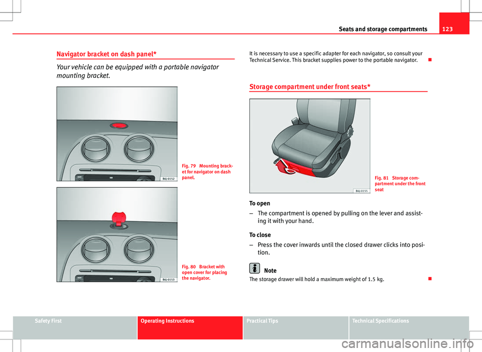
Navigator bracket on dash panel*
Your vehicle can be equipped with a portable navigator
mounting bracket.
Fig. 79 Mounting brack-
et for navigator on dash
panel.
Fig. 80 Bracket with
open cover for placing
the navigator. It is necessary to use a specific adapter for each navigator, so consult your
Technical Service. This bracket supplies power to the portable navigator.
Storage compartment under front seats*
Fig. 81 Storage com-
partment under the front
seat
To open
– The compartment is opened by pulling on the lever and assist-
ing it with your hand.
To close
– Press the cover inwards until the closed drawer clicks into posi-
tion.
Note
The storage drawer will hold a maximum weight of 1.5 kg.
Safety FirstOperating InstructionsPractical TipsTechnical Specifications
Page 127 of 282
125
Seats and storage compartments
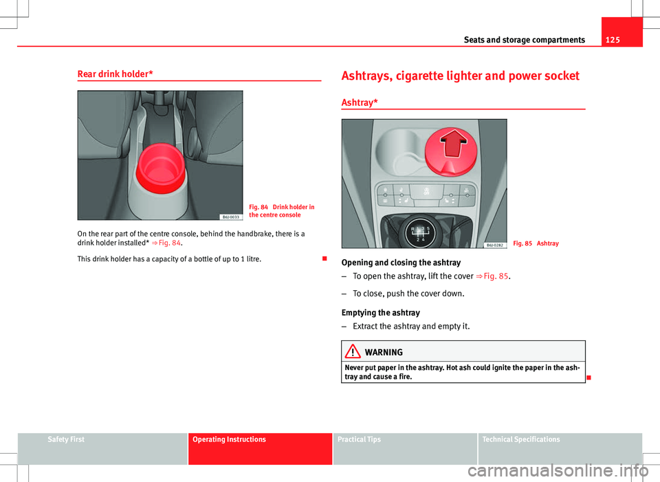
Rear drink holder*
Fig. 84 Drink holder in
the centre console
On the rear part of the centre console, behind the handbrake, there is a
drink holder installed* ⇒ Fig. 84.
This drink holder has a capacity of a bottle of up to 1 litre. Ashtrays, cigarette lighter and power socket
Ashtray*
Fig. 85 Ashtray
Opening and closing the ashtray
– To open the ashtray, lift the cover ⇒ Fig. 85.
– To close, push the cover down.
Emptying the ashtray
– Extract the ashtray and empty it.
WARNING
Never put paper in the ashtray. Hot ash could ignite the paper in the ash-
tray and cause a fire.
Safety FirstOperating InstructionsPractical TipsTechnical Specifications
Page 129 of 282
127
Seats and storage compartments
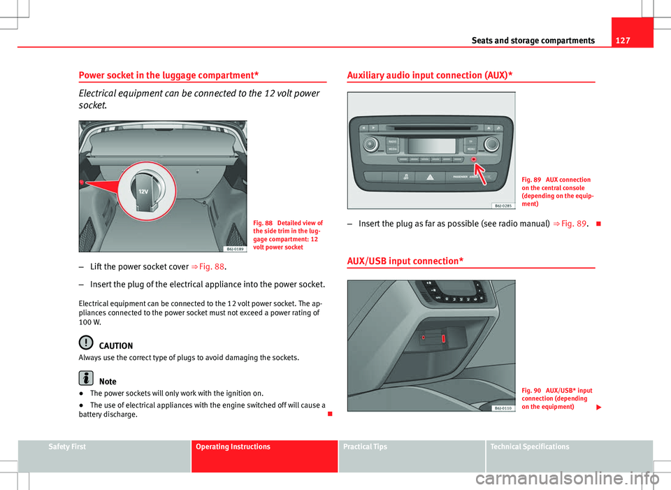
Power socket in the luggage compartment*
Electrical equipment can be connected to the 12 volt power
socket.
Fig. 88 Detailed view of
the side trim in the lug-
gage compartment: 12
volt power socket
– Lift the power socket cover ⇒ Fig. 88.
– Insert the plug of the electrical appliance into the power socket.
Electrical equipment can be connected to the 12 volt power socket. The ap-
pliances connected to the power socket must not exceed a power rating of
100 W.
CAUTION
Always use the correct type of plugs to avoid damaging the sockets.
Note
● The power sockets will only work with the ignition on.
● The use of electrical appliances with the engine switched off will cause a
battery discharge. Auxiliary audio input connection (AUX)*
Fig. 89 AUX connection
on the central console
(depending on the equip-
ment)
– Insert the plug as far as possible (see radio manual) ⇒ Fig. 89.
AUX/USB input connection*
Fig. 90 AUX/USB* input
connection (depending
on the equipment)
Safety FirstOperating InstructionsPractical TipsTechnical Specifications
Page 131 of 282
129
Seats and storage compartments
Luggage compartment
Loading the luggage compartment
Loads in the luggage compartment should be safely se-
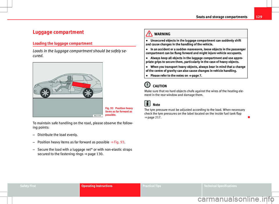
cured.
Fig. 93 Position heavy
items as far forward as
possible.
To maintain safe handling on the road, please observe the follow-
ing points:
– Distribute the load evenly.
– Position heavy items as far forward as possible ⇒ Fig. 93.
– Secure the load with a luggage net* or with non-elastic straps
secured to the fastening rings ⇒ page 130.
WARNING
● Unsecured objects in the luggage compartment can suddenly shift
and cause changes in the handling of the vehicle.
● In an accident or a sudden manoeuvre, loose objects in the passenger
compartment can be flung forward and might injure vehicle occupants.
● Always keep all objects in the luggage compartment and use appro-
priate grips to secure them, particularly in the case of heavy objects.
● When you transport heavy objects, always bear in mind that a change
of the centre of gravity can also cause changes in vehicle handling.
● Please refer to the notes on ⇒ page 7.
CAUTION
Make sure that no hard objects chafe against the wires of the heating ele-
ment in the rear window and damage them.
Note
The tyre pressure must be adjusted according to the load. When necessary
check the tyre pressures on the label located on the inside fuel tank flap
⇒ page 217.
Safety FirstOperating InstructionsPractical TipsTechnical Specifications
Page 133 of 282
131
Seats and storage compartments
Rear shelf
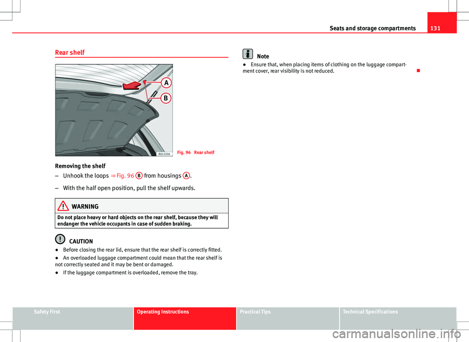
Fig. 96 Rear shelf
Removing the shelf
– Unhook the loops ⇒ Fig. 96 B
from housings A.
– With the half open position, pull the shelf upwards.
WARNING
Do not place heavy or hard objects on the rear shelf, because they will
endanger the vehicle occupants in case of sudden braking.
CAUTION
● Before closing the rear lid, ensure that the rear shelf is correctly fitted.
● An overloaded luggage compartment could mean that the rear shelf is
not correctly seated and it may be bent or damaged.
● If the luggage compartment is overloaded, remove the tray.
Note
● Ensure that, when placing items of clothing on the luggage compart-
ment cover, rear visibility is not reduced.
Safety FirstOperating InstructionsPractical TipsTechnical Specifications
Page 135 of 282
133
Seats and storage compartments
● It is essential that you follow the assembly instructions included with
the bars exactly, being especially careful to position the front and rear lug-
gage compartment cover bars on the special housings on the longitudinal
bars. You must also respect their position according to the direction of trav-
el indicated in the assembly manual. Not following these instructions may
cause marks on the longitudinal bars.
● Distribute the load evenly. A maximum load of 40 kg only is permitted
for each roof rack system support bar, the load must be distributed evenly
along the entire length. However, the maximum load permitted for the en-
tire roof (including the support system) of 75 kg must not be exceeded nor
should the total weight of the vehicle be exceeded. See the Technical Data
section.
● When transporting heavy or large objects on the roof, any change in the
normal vehicle behaviour due to a change in the centre of gravity or an in-
creased wind resistance must be taken into account. For this reason, a suit-
able speed and driving style must be used.
● For those vehicles fitted with a sliding/tilting sunroof*, ensure that it
does not interfere with the load on the roof rack system when opened.
Safety FirstOperating InstructionsPractical TipsTechnical Specifications
Page 137 of 282
135
Air conditioning
WARNING
● For your safety, the windows should never be fogged up or covered
with snow or ice. This is essential to ensure good visibility. Please famili-
arise yourself with the correct operation of the heating and ventilation
system, including the demist/defrost functions for the windows.
● In air recirculation mode, no cold air from the outside enters the vehi-
cle interior. The windows can quickly fog over if the heating is switched
off. Therefore, never leave the air recirculation mode switched on for a
long time (risk of accident).
Note
● Please consider the general notes ⇒ page 142.
Vehicle ventilation or heating
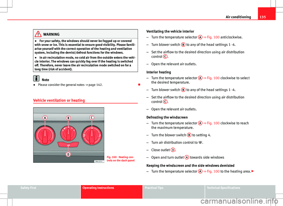
Fig. 100 Heating con-
trols on the dash panel Ventilating the vehicle interior
–
Turn the temperature selector A
⇒ Fig. 100 anticlockwise.
– Turn blower switch B
to any of the head settings 1 -4.
– Set the airflow to the desired direction using air distribution
control C
.
– Open the relevant air outlets.
Interior heating
– Turn the temperature selector A
⇒ Fig. 100 clockwise to select
the desired temperature.
– Turn blower switch B
to any of the head settings 1 -4.
– Set the airflow to the desired direction using air distribution
control C
.
– Open the relevant air outlets.
Defrosting the windscreen
– Turn the temperature selector A
⇒ Fig. 100 clockwise to reach
the maximum temperature.
– Turn the blower switch B
to setting 4.
– Turn air distribution control to .
– Close outlet 3
.
– Open and turn outlet 4
towards side windows
Keeping the windscreen and the side windows demisted
– Turn the temperature selector A
⇒ Fig. 100 to the heating area.
Safety FirstOperating InstructionsPractical TipsTechnical Specifications
Page 139 of 282
137
Air conditioning
Air distribution C
Switch on symbolMain air output through outlets:
1,2
5
1, 2, 5
3, 4
Outlets 3 and 4 can be closed or opened separately and the air flow di-
rected as required.
Air conditioning* Controls
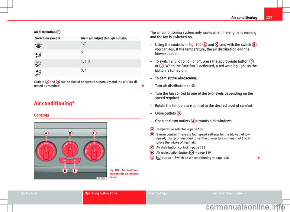
Fig. 102 Air condition-
ing controls on the dash
panel The air conditioning system only works when the engine is running
and the fan is switched on.
–
Using the controls ⇒ Fig. 102 A
and C and with the switch Byou can adjust the temperature, the air distribution and the
blower speed.
– To switch a function on or off, press the appropriate button D
or E. When the function is activated, a red warning light on the
button is turned on.
– To demist the windscreen:
– Turn air distribution to .
– Turn the fan control to one of the two levels depending on the
speed required.
– Rotate the temperature control to the desired level of comfort.
– Close outlets 3
–
Open and turn outlets 4 towards side windows.
Temperature selector ⇒ page 138
Blower control. There are four speed settings for the blower. At low
speed, it is recommended to set the blower to a minimum of 1 to im-
prove the intake of fresh air.
Air distribution control ⇒ page 138
Air recirculation button
⇒ page 139
AC button – Switch on air conditioning ⇒ page 138
A
B
CDE
Safety FirstOperating InstructionsPractical TipsTechnical Specifications
Page 141 of 282
139
Air conditioning
● The outside temperature is below +3°C.
● The air conditioning system compressor has been temporarily switched
off because of an increased engine coolant temperature.
● The air conditioner fuse is faulty.
● Another fault in the vehicle. Have the air conditioning checked by a spe-
cialised workshop.
Air recirculation
Air recirculation mode prevents fumes or unpleasant smells
from coming from the outside.
When air recirculation mode is switched on (button ⇒ Fig. 103
with
warning lamp) strong odours in the outside air do not enter the vehicle inte-
rior, for example when passing through a tunnel or in a traffic jam.
When the outside temperature is low, air recirculation mode improves heat-
ing performance by heating air from the interior instead of cold air from the
outside.
When the outside temperature is high, air recirculation mode improves cool-
ing performance by cooling air from the interior instead of warm air from
outside.
For safety reasons, the air recirculation should not be switched on when the
air distribution control is set to the windscreen setting .
WARNING
In air recirculation mode, no cold air from the outside enters the vehicle
interior. If the air conditioner is switched off, the windows can quickly
mist over. Therefore, never leave the air recirculation mode switched on
for a long time (risk of accident).
Note
● When engaging reverse gear, the air recirculation is connected automat-
ically to prevent the entrance of exhaust gases in the vehicle on travelling
backwards. The control lamp on the button
does not light up.
● If the temperature control is turned to the coldest setting (blue point)
and the switch AC
is activated, the “Air recirculation” function is automati-
cally activated in order to cool the vehicle rapidly using less energy; its
function control lamp will light.
● If the function is not deactivated by pressing the button, this will deacti-
vate after approx. 20 min.
Economic use of the air conditioning
When the air conditioning is switched on, the compressor consumes engine
power and has influence on fuel consumption. Consider the following
points in order to have the system operating in the minimum possible time.
● If the vehicle interior has overheated due to an excessive solar radiation,
it is best to open the windows or doors to allow the hot air to escape.
● While in motion, the air conditioning should not be switched on if the
windows or the sunroof are open.*
Safety FirstOperating InstructionsPractical TipsTechnical Specifications
Page 143 of 282
141
Air conditioning
Automatic mode
In automatic mode air temperature, air flow and distribution
are automatically regulated so that a specified temperature
is attained as quickly as possible, and then maintained. Switching on automatic mode
– Press the button AUTO
. The indication
⇒ Fig. 104 3 is dis-
played.
– Press keys 10
and 11 ⇒ Fig. 104 to adjust the desired tempera-
ture inside the vehicle. We recommend you adjust the tempera-
ture to 22°C (72°F).
A comfortable interior climate is quickly reached when a temperature of
22°C (72°F) is set in automatic mode. Therefore, we recommend you not to
change this adjustment, except as necessary to suit individual preferences
or particular circumstances. The inside temperature can be set between
+18°C (64°F) and +29°C (86°F). If a lower or higher temperature is selected,
LO or HI are respectively displayed on the screen. These are approximate
temperatures which may slightly vary depending on the outside conditions.
Climatronic maintains a constant temperature. To do so, it automatically
regulates the supplied air temperature, the blower speed and the air distri-
bution. The system also considers the sunlight radiation, so there is no
need for manual readjustment. Therefore, automatic mode almost always
provides the best comfort for the vehicle occupants throughout the year.
Automatic mode is switched off whenever an adjustment is made using the
buttons for air distribution or blower. The temperature continues to self-reg-
ulate. Manual mode
In manual mode the air temperature, flow, and the desired
air distribution can be adjusted.
Switching on manual mode
– Press one of the buttons ⇒ Fig. 104 14
to 16 or press the blow-
er control 8 and 9 down. The indicator is switched off 3.
Temperature
The inside temperature can be set between +18°C (64°F) and +29°C (86°F).
These are approximate temperatures which may slightly vary depending on
the outside conditions.
If a temperature below 18°C (64°F), is selected, the display switches to LO In
this setting the system runs at maximum cooling output and the tempera-
ture is not regulated.
If a temperature above 29°C (86°F) is selected, the display switches to HI In
this setting the system runs at maximum heating output and the tempera-
ture is not controlled.
Blower
The blower can be adjusted with buttons 8
and 9 ⇒ Fig. 104. If the blow-
er is off (level 1 is not shown on the screen) and button 9 is pressed after
1 second, the Climatronic switches off.
Air distribution
The air distribution is adjusted using the buttons
, and . It is also
possible to open and close some of the air outlets separately.
Switching the air conditioning on and off
Pressing the button AC
the air cooling system can be switched off in order
to save fuel. The temperature continues to self-regulate. The set tempera-
ture can then only be reached if it is higher than the outside temperature.
Safety FirstOperating InstructionsPractical TipsTechnical Specifications