oil change Seat Ibiza ST 2012 Owner's manual
[x] Cancel search | Manufacturer: SEAT, Model Year: 2012, Model line: Ibiza ST, Model: Seat Ibiza ST 2012Pages: 282, PDF Size: 3.77 MB
Page 6 of 282
Accessories, replacement of parts and
modifications . . . . . . . . . . . . . . . . . . . . . . . . . . . . . 190
Accessories and spare parts . . . . . . . . . . . . . . . . 190
Technical modifications . . . . . . . . . . . . . . . . . . . . 190
Roof aerial* . . . . . . . . . . . . . . . . . . . . . . . . . . . . . . 191
Mobile telephones and two-way radios . . . . . . . . 191
Fitting a towing bracket* . . . . . . . . . . . . . . . . . . . 192
Checking and refilling levels . . . . . . . . . . . . . . . 194
Refuelling . . . . . . . . . . . . . . . . . . . . . . . . . . . . . . . 194
LPG system* . . . . . . . . . . . . . . . . . . . . . . . . . . . . . 196
Petrol . . . . . . . . . . . . . . . . . . . . . . . . . . . . . . . . . . . 199
Diesel . . . . . . . . . . . . . . . . . . . . . . . . . . . . . . . . . . . 199
Working in the engine compartment . . . . . . . . . . 200
Engine oil . . . . . . . . . . . . . . . . . . . . . . . . . . . . . . . . 203
Coolant . . . . . . . . . . . . . . . . . . . . . . . . . . . . . . . . . 207
Washer fluid and windscreen wiper blades . . . . 209
Brake fluid . . . . . . . . . . . . . . . . . . . . . . . . . . . . . . . 213
Vehicle battery . . . . . . . . . . . . . . . . . . . . . . . . . . . 214
Wheels . . . . . . . . . . . . . . . . . . . . . . . . . . . . . . . . . . 216
If and when . . . . . . . . . . . . . . . . . . . . . . . . . . . . . . . 223
Vehicle tools, spare wheel . . . . . . . . . . . . . . . . . . 223
Wheel change . . . . . . . . . . . . . . . . . . . . . . . . . . . . 224
Tyre repair kit (Tyre-Mobility-System)* . . . . . . . . . 229
Fuses . . . . . . . . . . . . . . . . . . . . . . . . . . . . . . . . . . . 231
Bulb change . . . . . . . . . . . . . . . . . . . . . . . . . . . . . 234
Single headlight bulb change . . . . . . . . . . . . . . . 236
Double headlight bulb change . . . . . . . . . . . . . . . 238
Changing the bulbs of AFS headlights . . . . . . . . 242
Changing the fog light bulbs . . . . . . . . . . . . . . . . 243
Changing the rear lights (on the wing) . . . . . . . . 244
Changing the rear lights (on the rear lid) . . . . . . 245
Side turn signal bulbs . . . . . . . . . . . . . . . . . . . . . . 246
Number plate light . . . . . . . . . . . . . . . . . . . . . . . . 247
Interior light and front reading lights . . . . . . . . . 247
Additional brake lights* . . . . . . . . . . . . . . . . . . . . 248
Luggage compartment light . . . . . . . . . . . . . . . . . 248 Jump-starting . . . . . . . . . . . . . . . . . . . . . . . . . . . . . 248
Towing and tow-starting . . . . . . . . . . . . . . . . . . . . 252
Technical Specifications . . . . . . . . . . . 255
Description of specifications . . . . . . . . . . . . . . . 255
Important information . . . . . . . . . . . . . . . . . . . . . 255
Information on fuel consumption . . . . . . . . . . . . 257
Towing a trailer . . . . . . . . . . . . . . . . . . . . . . . . . . . 257
Wheels . . . . . . . . . . . . . . . . . . . . . . . . . . . . . . . . . . 258
Technical specifications . . . . . . . . . . . . . . . . . . . . 259
Checking fluid levels . . . . . . . . . . . . . . . . . . . . . . . 259
Petrol engine 1.2 51 kW (70 PS) . . . . . . . . . . . . . 260
Petrol engine 1.2 TSI 63 kW (85 PS) . . . . . . . . . . 261
Petrol engine 1.4 63 kW (85 PS) . . . . . . . . . . . . . 262
Petrol engine 1.2 TSI 77 kW (105 PS) . . . . . . . . . 263
Petrol engine 1.2 TSI 77 kW (105 PS) Start-Stop 264
Petrol engine 1.4 TSI 110 kW (150 PS) automatic . .265
Diesel engine 1.2 TDI CR 55 kW (75 PS) DPF
Start-Stop Ecomotive . . . . . . . . . . . . . . . . . . . . . . 266
Diesel engine 1.2 TDI CR 55 kW (75 PS) DPF . . . . 267
Diesel engine 1.6 TDI CR 66 kW (90 PS) DPF . . . . 268
Diesel engine 1.6 TDI CR 77 kW (105 PS) with/
without DPF . . . . . . . . . . . . . . . . . . . . . . . . . . . . . . 269
Dimensions and capacities . . . . . . . . . . . . . . . . . 270
Index . . . . . . . . . . . . . . . . . . . . . . . . . . . . . . . . . . . 271
4Table of Contents
Page 65 of 282
63
Cockpit
This may be deactivated by pressing the RESET
button. The speed may be
altered using the rocker switch B in steps of 5 km/h (mph) within 5 sec-
onds of the initial memory value.
WARNING
There could be black ice on the road surface even if the “snowflake sym-
bol” is not shown. For this reason you should not rely exclusively on this
display - Risk of accident!
Note
When the vehicle is stationary or travelling at very low speeds, the tempera-
ture displayed may be slightly higher than the actual outside temperature
as a result of the heat radiated from the engine.
Display field for selector lever position*
Fig. 36 Digital display:
Gearbox lever position
for automatic gearbox. The position of the automatic selector lever is shown on the display
⇒ page 154.
Odometer
The upper counter in the display registers the total mileage covered by the
vehicle.
The lower counter registers the short journeys. The last digit indicates 100-
metre sections. The trip recorder counter may be reset by pressing the reset
button ⇒ Fig. 30 5
.
Service interval display
Fig. 37 Service interval
display
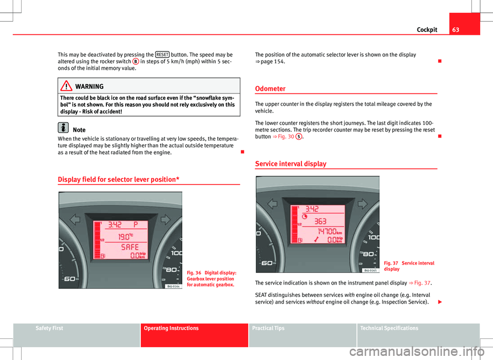
The service indication is shown on the instrument panel display ⇒ Fig. 37.
SEAT distinguishes between services with engine oil change (e.g. Interval
service) and services without engine oil change (e.g. Inspection Service).
Safety FirstOperating InstructionsPractical TipsTechnical Specifications
Page 66 of 282
64Cockpit
The service interval display only indicates the dates of services that include
engine oil change. The dates of all other services, such as Inspection Serv-
ice or brake fluid change, appear in the sticker on the door pillar or in the
Maintenance Programme.
Vehicles with service intervals dependent on time/distance travelled al-
ready have certain service intervals set.
The intervals are calculated separately in vehicles with LongLife service.
Technical progress has made it possible to considerably reduce servicing re-
quirements. With the LongLife System, SEAT ensures that your vehicle only
has an interval service when it is necessary. To calculate this (max. two
years), the conditions under which the vehicle is used and the individual
driving style are also taken into account. The service pre-warning will ap-
pear at 20 days or less prior to the corresponding service. The distance trav-
elled is rounded off to the nearest 100 km (miles) and the time to full days.
The current service message can only be consulted 500 km (miles) or more
after the last service. Until that time, only dashes are displayed.
Service warning
A service warning will appear when the ignition is switched on if a service is
due soon.
The instrument panel display will show the “spanner symbol” and the
“km (miles)” indication, along with a clock symbol with the days remaining
until the date of the next service. The figure indicated is the maximum num-
ber of kilometres (miles) remaining before the date of the next service. The
indication changes after a few seconds. A “clock symbol” appears and the
number of days until the service appointment should be carried out.
Service
If a service is due, an audible warning will sound and the flashing “span-
ner” symbol will be shown along with the fixed text SERVICE.
If no service is carried out following the indication on the instrument panel,
the excess distance travelled and the excess time following the SERVICE
warning will be displayed. Reading the service message
The current service message
can be consulted with the ignition on, the en-
gine switched off and the vehicle at a standstill:
● Press the
button on the instrument panel as often as necessary until
the spanner symbol is displayed.
An overdue service is indicated by a minus sign in front of the mileage or
day information.
Resetting service interval display
If the service was not performed by a SEAT dealership, the display must be
reset as follows:
● Switch the ignition off.
● Press and hold the 0.0 / SET
button.
● Switch ignition back on.
● Release the 0.0 / SET
button and press the button within 20 seconds.
Do not reset the display between service intervals, as the display will other-
wise be incorrect.
If the display is reset manually, the next service interval will be indicated af-
ter 15 000 km (10 000 miles) or one year and will not be calculated individ-
ually.
Note
In LongLife Service vehicles, if the battery is disconnected for a long period,
the days remaining until the next service cannot be calculated. Therefore,
the service message indications may be incorrect. In this case, bear in mind
the maximum service intervals permitted in the ⇒ Booklet Maintenance Pro-
gramme.
Page 176 of 282
174Driving and the environment
recommend that you have the thickness of your brake pads checked by a
Technical Service more frequently than recommended in the Maintenance
Programme.
If you drive with wet brakes, for example, after crossing areas of water, in
heavy rainfall or even after washing the vehicle, the effect of the brakes is
lessened as the brake discs are wet or even frozen (in winter). In this case
the brakes should be dried by pressing the brake pedal several times.
WARNING
Longer braking distances and faults in the brake system increase the risk
of accidents.
● New brake pads must be run in and do not have the correct friction
during the first 200 km (120 miles). However, the reduced braking ca-
pacity may be compensated by pressing on the brake pedal a little hard-
er. This also applies when the brake pads have to be changed further on.
● If brakes are wet or frozen, or if you are driving on roads which have
been salted, braking power may be lower than normal.
● On steep slopes, if brakes are excessively used, they will overheat.
Before driving down a long steep slope, it is advisable to reduce speed
and change down into a lower gear or range (depending on the type of
transmission). This makes use of engine braking and relieves the brakes.
● Never let the brakes “drag” by applying light pressure. Continuous
braking will cause the brakes to overheat and the braking distance will
increase. Apply and then release the brakes alternately.
● Never let the vehicle run with the engine switched off. The braking
distance is increased considerably when the brake servo is not active.
● If the brake fluid loses its viscosity and is subjected to heavy use, va-
pour bubbles can form in the brake system. This reduces the efficiency of
the brakes.
WARNING (Continued)
● Non-standard or damaged front spoilers could restrict the airflow to
the brakes and cause them to overheat. Before purchasing accessories
please observe the relevant instructions ⇒ page 190, Technical modifi-
cations.
● If a brake system circuit fails, the braking distance will be increased
considerably. Contact a specialised workshop immediately and avoid un-
necessary journeys.
Exhaust gas purification system Catalytic converter*
To maintain the useful life of the catalytic converter
– Use only unleaded petrol with petrol engines, as lead damages
the catalytic converter.
– Do not let the fuel get too low in the tank.
– For engine oil changes, do not replenish with too much engine
oil ⇒ page 206, Topping up engine oil .
– Never tow the vehicle to start it, use jump leads if necessary
⇒ page 248.
If you notice misfiring, uneven running or loss of power when the vehicle is
moving, reduce speed immediately and have the vehicle inspected at the
nearest specialised workshop. In general, the exhaust gas warning lamp
will light up when any of the described symptoms occur ⇒ page 65. If this
happens, unburnt fuel can enter the exhaust system and escape into the en-
vironment. The catalytic converter can also be damaged by overheating.
Page 205 of 282
203
Checking and refilling levels
WARNING (Continued)
● Wait until no more steam, smoke or coolant is emitted from the bon-
net, then carefully open the bonnet.
● When working in the engine compartment, always observe the safety
warnings ⇒ page 200.
Closing the bonnet
– Slightly raise the bonnet
– Release the bonnet stay and replace it in its support.
– At a height of about 30 cm let it fall so it is locked.
If the bonnet does not close, do not press downwards. Open it once more
and let it fall as before.
WARNING
If the bonnet is not closed properly, it could open while you are driving
and completely obscure your view of the road. Risk of accident.
● After closing the bonnet, always check that it is properly secured. The
bonnet must be flush with the surrounding body panels.
● If you notice that the bonnet latch is not secured when the vehicle is
moving, stop the vehicle immediately and close the bonnet properly.
Risk of accident.
Engine oil
General notes
The engine comes with a special, multi-grade oil that can be used all year
round.
Because the use of high-quality oil is essential for the correct operation of
the engine and its long useful life, when topping up or changing oil, use on-
ly those oils that comply with VW standards.
The specifications (VW standards) set out in the following page should ap-
pear on the container of the service oil; when the container displays the
specific standards for petrol and diesel engines together, it means that the
oil can be used for both types of engines.
We recommend that the oil change, indicated in the Maintenance Pro-
gramme, be performed by a Technical Service or a specialised workshop.
The correct oil specifications for your engine are listed in ⇒ page 204, Oil
properties.
Service intervals
Service intervals can be flexible (LongLife service) or fixed (dependent on
time/distance travelled).
If the PR code that appears on the back of the “Maintenance Programme”
booklet is QG1, this means that your vehicle has the LongLife service pro-
grammed. If it has the codes QG0 or QG2 the interval service is dependent
on time/distance travelled.
Flexible service intervals (LongLife service intervals*)
Special oils and processes have been developed which, depending on the
characteristics and individual driving profiles, enable the extension of the
oil change service (LongLife service intervals).
Safety FirstOperating InstructionsPractical TipsTechnical Specifications
Page 208 of 282
206Checking and refilling levels
Topping up engine oil
Top up gradually with small quantities of engine oil.
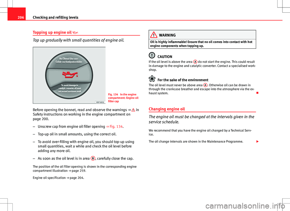
Fig. 134 In the engine
compartment: Engine oil
filler cap
Before opening the bonnet, read and observe the warnings ⇒
in
Safety instructions on working in the engine compartment on
page 200.
– Unscrew cap from engine oil filler opening ⇒ Fig. 134.
– Top-up oil in small amounts, using the correct oil.
– To avoid over-filling with engine oil, you should top-up using
small quantities, wait a while and check the oil level before
adding any more oil.
– As soon as the oil level is in area B
, carefully close the cap.
The position of the oil filler opening is shown in the corresponding engine
compartment illustration ⇒ page 259.
Engine oil specification ⇒ page 204.
WARNING
Oil is highly inflammable! Ensure that no oil comes into contact with hot
engine components when topping up.
CAUTION
If the oil level is above the area A do not start the engine. This could result
in damage to the engine and catalytic converter. Contact a specialised work-
shop.
For the sake of the environment
The oil level must never be above area A. Otherwise oil can be drawn in
through the crankcase breather and escape into the atmosphere via the ex-
haust system.
Changing engine oil
The engine oil must be changed at the intervals given in the
service schedule. We recommend that you have the engine oil changed by a Technical Serv-
ice.
The oil change intervals are shown in the Maintenance Programme.
Page 209 of 282
207
Checking and refilling levels
WARNING
Only change the engine oil yourself if you have the specialist knowledge
required!
● Before opening the bonnet, read and observe the warnings
⇒ page 200, Safety instructions on working in the engine compartment.
● Wait for the engine to cool down. Hot oil may cause burn injuries.
● Wear eye protection to avoid injuries, such as acid burns, caused by
splashes of oil.
● When removing the oil drain plug with your fingers, keep your arm
horizontal to help prevent oil from running down your arm.
● Wash your skin thoroughly if it comes into contact with engine oil.
● Engine oil is poisonous! Used oil must be stored in a safe place out of
the reach of children.
CAUTION
No additives should be used with engine oil. This could result in engine
damage. Any damage caused by the use of such additives would not be
covered by the factory warranty.
For the sake of the environment
● Because of the disposal problems, the necessary special tools and spe-
cialist knowledge required, we recommend that you have the engine oil and
filter changed by a Technical Service.
● Never pour oil down drains or into the ground.
● Use a suitable container when draining the used oil. It must be large
enough to hold all the engine oil. Coolant
Engine coolant specifications
The engine cooling system is supplied from the factory with a specially trea-
ted mixture of water and, at least, 40 % of the additive G 13 (TL-VW 774 J).
The engine coolant additive is recognisable by its purple colour. This mix-
ture of water and additive gives the necessary frost protection down to
-25°C (-13°F) and protects the light alloy parts of the cooling system against
corrosion. It also prevents scaling and considerably raises the boiling point
of the coolant.
To protect the engine cooling system, the percentage of additive must al-
ways be at least 40 %, even in warm climates where anti-freeze protection is
not required.
If greater frost protection is required in very cold climates, the proportion of
additive can be increased. However, the percentage of additive should not
exceed 60 %, as this would reduce the frost protection and, in turn, de-
crease the cooling capacity.
When the coolant is topped up, use a mixture of distilled water and, at
least, 40 % of the G 13 or G 12 plus-plus (TL-VW 774 G) additive (both are
purple) to obtain an optimum anticorrosion protection ⇒
. The mixture of
G 13 with G 12 plus (TL-VW 774 F), G 12 (red) or G 11 (green-blue) engine
coolants will significantly reduce the anticorrosion protection and should,
therefore be avoided ⇒
.
Safety FirstOperating InstructionsPractical TipsTechnical Specifications
Page 213 of 282
211
Checking and refilling levels
To change the blades it is necessary to change the rest position of
the wipers to the service position.
Do not change the windscreen wipers when out of the service posi-
tion, as it could cause paint to flake off the bonnet due to friction
with the windscreen wiper arm.
Service position (For changing wiper blades)
– Ensure that the wiper blades are not frozen.
– Turn ignition on and off and then (before approx. 9 sec.) move
the windscreen wiper lever to the intermittent wipe position.
The windscreen wipers will move to the service position
⇒ Fig. 137.
Removing the wiper blade
– Lift the windscreen wiper arm.
– Press on the securing tab ⇒ Fig. 138.
– Extract the wiper blade from the wiper arm.
Fitting the wiper blade
– Insert the wiper blade onto the windscreen wiper arm until it
clicks into place.
– Place the windscreen wiper arms to their initial position.
If the windscreen wipers smear , they should be replaced if they are dam-
aged, or cleaned if they are soiled.
If this does not produce the desired results, the setting angle of the wind-
screen wiper arms might be incorrect. They should be checked by a special-
ised workshop and corrected if necessary.
WARNING
Do not drive unless you have good visibility through all windows!
● Clean the windscreen wiper blades and all windows regularly.
● The wiper blades should be changed once or twice a year.
CAUTION
● Damaged or dirty windscreen wipers could scratch the windscreen.
● Never use fuel, nail varnish remover, paint thinner or similar products to
clean the windows. This could damage the windscreen wiper blades.
● Never move the windscreen wiper or windscreen wiper arm manually.
This could cause damage.
● To avoid damage to the bonnet and the windscreen wiper arms, the lat-
ter should only be lifted off the windscreen when in service position.
Note
● The windscreen wiper arms can be moved to the service position only
when the bonnet is properly closed.
● You can also use the service position, for example, if you want to fix a
cover over the windscreen in the winter to keep it clear of ice.
Safety FirstOperating InstructionsPractical TipsTechnical Specifications
Page 214 of 282
212Checking and refilling levels
Changing the rear wiper blade
A good rear wiper blade is essential for clear rear vision.
Damaged wiper blades should be replaced immediately.
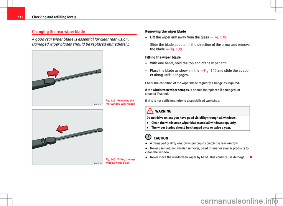
Fig. 139 Removing the
rear window wiper blade
Fig. 140 Fitting the rear
window wiper blade Removing the wiper blade
–
Lift the wiper arm away from the glass ⇒ Fig. 139.
– Slide the blade adapter in the direction of the arrow and remove
the blade ⇒ Fig. 139.
Fitting the wiper blade
– With one hand, hold the top end of the wiper arm.
– Place the blade as shown in the ⇒ Fig. 140 and slide the adapt-
er along until it engages.
Check the condition of the wiper blade regularly. Change as required.
If the windscreen wiper scrapes, it should be replaced if damaged, or
cleaned if soiled.
If this is not sufficient, refer to a specialised workshop.
WARNING
Do not drive unless you have good visibility through all windows!
● Clean the windscreen wiper blades and all windows regularly.
● The wiper blades should be changed once or twice a year.
CAUTION
● A damaged or dirty window wiper could scratch the rear window.
● Never use fuel, nail varnish remover, paint thinner or similar products to
clean the window.
● Never move the windscreen wiper by hand. This could cause damage.
Page 215 of 282
213
Checking and refilling levels
Brake fluid Checking the brake fluid level
The brake fluid is checked at the intervals given in the serv-
ice schedule.
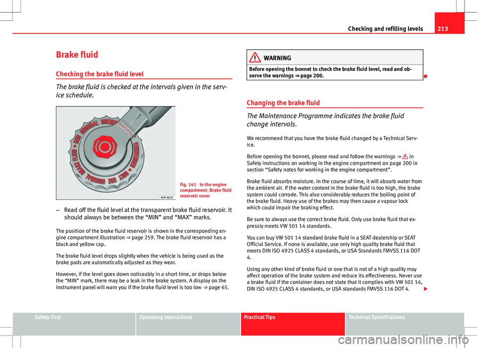
Fig. 141 In the engine
compartment: Brake fluid
reservoir cover
– Read off the fluid level at the transparent brake fluid reservoir. It
should always be between the “MIN” and “MAX” marks.
The position of the brake fluid reservoir is shown in the corresponding en-
gine compartment illustration ⇒ page 259. The brake fluid reservoir has a
black and yellow cap.
The brake fluid level drops slightly when the vehicle is being used as the
brake pads are automatically adjusted as they wear.
However, if the level goes down noticeably in a short time, or drops below
the “MIN” mark, there may be a leak in the brake system. A display on the
instrument panel will warn you if the brake fluid level is too low ⇒ page 65.
WARNING
Before opening the bonnet to check the brake fluid level, read and ob-
serve the warnings ⇒ page 200.
Changing the brake fluid
The Maintenance Programme indicates the brake fluid
change intervals. We recommend that you have the brake fluid changed by a Technical Serv-
ice.
Before opening the bonnet, please read and follow the warnings ⇒
in
Safety instructions on working in the engine compartment on page 200 in
section “Safety notes for working in the engine compartment”.
Brake fluid absorbs moisture. In the course of time, it will absorb water from
the ambient air. If the water content in the brake fluid is too high, the brake
system could corrode. This also considerably reduces the boiling point of
the brake fluid. Heavy use of the brakes may then cause a vapour lock
which could impair the braking effect.
Be sure to always use the correct brake fluid. Only use brake fluid that ex-
pressly meets VW 501 14 standards.
You can buy VW 501 14 standard brake fluid in a SEAT dealership or SEAT
Official Service. If none is available, use only high quality brake fluid that
meets DIN ISO 4925 CLASS 4 standards, or USA Standards FMVSS 116 DOT
4.
Using any other kind of brake fluid or one that is not of a high quality may
affect operation of the brake system and reduce its effectiveness. Never use
a brake fluid if the container does not state that it complies with VW 501 14,
DIN ISO 4925 CLASS 4 standards, or USA standards FMVSS 116 DOT 4.
Safety FirstOperating InstructionsPractical TipsTechnical Specifications