fuel cap Seat Ibiza ST 2013 Owner's manual
[x] Cancel search | Manufacturer: SEAT, Model Year: 2013, Model line: Ibiza ST, Model: Seat Ibiza ST 2013Pages: 294, PDF Size: 4.05 MB
Page 6 of 294
Accessories, replacement of parts and
modifications . . . . . . . . . . . . . . . . . . . . . . . . . . . . . 196
Accessories and spare parts . . . . . . . . . . . . . . . . 196
Technical modifications . . . . . . . . . . . . . . . . . . . . 196
Roof aerial* . . . . . . . . . . . . . . . . . . . . . . . . . . . . . . 197
Mobile telephones and two-way radios . . . . . . . . 197
Fitting a towing bracket* . . . . . . . . . . . . . . . . . . . 198
Checking and refilling levels . . . . . . . . . . . . . . . 200
Refuelling . . . . . . . . . . . . . . . . . . . . . . . . . . . . . . . 200
LPG system* . . . . . . . . . . . . . . . . . . . . . . . . . . . . . 202
Petrol . . . . . . . . . . . . . . . . . . . . . . . . . . . . . . . . . . . 205
Diesel . . . . . . . . . . . . . . . . . . . . . . . . . . . . . . . . . . . 205
Working in the engine compartment . . . . . . . . . . 206
Engine oil . . . . . . . . . . . . . . . . . . . . . . . . . . . . . . . . 209
Coolant . . . . . . . . . . . . . . . . . . . . . . . . . . . . . . . . . 213
Washer fluid and windscreen wiper blades . . . . 215
Brake fluid . . . . . . . . . . . . . . . . . . . . . . . . . . . . . . . 219
Vehicle battery . . . . . . . . . . . . . . . . . . . . . . . . . . . 220
Wheels . . . . . . . . . . . . . . . . . . . . . . . . . . . . . . . . . . 222
If and when . . . . . . . . . . . . . . . . . . . . . . . . . . . . . . . 229
Vehicle tools, spare wheel . . . . . . . . . . . . . . . . . . 229
Wheel change . . . . . . . . . . . . . . . . . . . . . . . . . . . . 230
Tyre repair kit* (Tyre Mobility-System) . . . . . . . . . 235
Fuses . . . . . . . . . . . . . . . . . . . . . . . . . . . . . . . . . . . 237
Bulb change . . . . . . . . . . . . . . . . . . . . . . . . . . . . . 239
Single headlight bulb change . . . . . . . . . . . . . . . 241
Double headlight bulb change . . . . . . . . . . . . . . . 243
Changing the bulbs of AFS headlights . . . . . . . . 247
Changing the fog light bulbs . . . . . . . . . . . . . . . . 248
Changing rear bulbs . . . . . . . . . . . . . . . . . . . . . . . 249
Changing the rear lights (on the wing) . . . . . . . . 251
Changing the rear lights (on the rear lid) . . . . . . 253
Changing the side and interior light bulbs . . . . . 254
Jump-starting . . . . . . . . . . . . . . . . . . . . . . . . . . . . . 256
Towing and tow-starting . . . . . . . . . . . . . . . . . . . . 259 Technical Specifications
. . . . . . . . . . . 262
Description of specifications . . . . . . . . . . . . . . . 262
Important information . . . . . . . . . . . . . . . . . . . . . 262
Information on fuel consumption . . . . . . . . . . . . 264
Towing a trailer . . . . . . . . . . . . . . . . . . . . . . . . . . . 265
Wheels . . . . . . . . . . . . . . . . . . . . . . . . . . . . . . . . . . 265
Technical specifications . . . . . . . . . . . . . . . . . . . . 267
Checking fluid levels . . . . . . . . . . . . . . . . . . . . . . . 267
Petrol engine 1.2 44 kW (60 PS) . . . . . . . . . . . . . 268
Petrol engine 1.2 51 kW (70 PS) . . . . . . . . . . . . . 269
Petrol engine/LPG 1.6 60 kW (81 PS) . . . . . . . . . 270
Petrol engine 1.2 TSI 63 kW (85 PS) . . . . . . . . . . 271
Petrol engine 1.4 63 kW (85 PS) . . . . . . . . . . . . . 272
Petrol engine 1.2 TSI 77 kW (105 PS) . . . . . . . . . 273
Petrol engine 1.2 TSI 77 kW (105 PS) Start-Stop 274
Petrol engine 1.6 77 kW (105 PS) . . . . . . . . . . . . 275
Petrol engine 1.4 TSI 110 kW (150 PS) . . . . . . . . 276
Petrol engine 1.4 132 kW (180 PS) - Cupra . . . . . 277
Diesel engine 1.2 TDI CR 55 kW (75 PS) . . . . . . . 278
Diesel engine 1.6 TDI CR 66 kW (90 PS) DPF . . . . 279
Diesel engine 1.6 TDI CR 77 kW (105 PS) with/
without DPF . . . . . . . . . . . . . . . . . . . . . . . . . . . . . . 280
Diesel engine 2.0 TDI CR 105 kW (143 PS) DPF . 281
Dimensions . . . . . . . . . . . . . . . . . . . . . . . . . . . . . . 282
Capacities . . . . . . . . . . . . . . . . . . . . . . . . . . . . . . . 282
Index . . . . . . . . . . . . . . . . . . . . . . . . . . . . . . . . . . . 283
4Table of Contents
Page 60 of 294
58Cockpit
Rev counter
The rev counter displays the engine speed in revolutions per
minute.
The start of the red zone ⇒ Fig. 30 1
indicates the maximum engine speed
operating at service temperature. However, it is advisable to change up into
a higher gear, move the selector lever to D or lift your foot off the accelerator
before the needle reaches the red zone.
CAUTION
To prevent possible engine malfunctions, the rev counter needle should not
reach the red zone. The start of the red zone on the dial is different for some
engine versions.
For the sake of the environment
Changing up into higher gears sooner, following the recommended gear in-
dications ⇒ Fig. 33 will help you to reduce fuel consumption, emissions and
also engine noise.
Speedometer
The speedometer is equipped with a digital odometer and a trip recorder, in
addition to a service intervals display.
During the running-in period, the instructions shown on ⇒ page 179
should be followed. LPG system*
LPG gauge
Fig. 31 Instrument pan-
el: gas gauge.
LPG system filler level display
The LPG tank ⇒
in the spare wheel well has a capacity of 52.8 litres at an
outside temperature of +15 °C (+59 °F) ⇒ page 202, Refuelling with LPG.
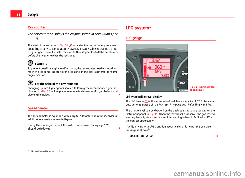
The charge level can be checked on the analogue gas gauge located on the
instrument panel ⇒ Fig. 31. When the level reaches reserve, the gas reserve
warning lamp lights up and an audible warning is heard. Refill with LPG at
the earliest opportunity.
If while driving with LPG a sudden acoustic signal is heard, the on-screen
message is shown 1)
:
ERROR FUNC_ A GAS
1)
Depending on the model version
Page 61 of 294
59
Cockpit
It means there is a fault in the LPG system. Take the vehicle to a specialised
workshop to check the LPG system.
WARNING
LPG is a highly explosive and inflammable substance. It may cause se-
vere burns and other injury.
● Due care must be taken to avoid any risk of fire or explosion.
● When parking the vehicle in a closed area (for example in a garage),
make sure that there is adequate ventilation, either natural or mechani-
cal, to neutralise the LPG in the event of a leak.
Note
● The values shown in the average fuel consumption and distance to emp-
ty indications on the multifunction display (MFI) 1)
on the instrument panel
display 2)
are approximate values only.
● Two different consumption values are given on the MFI, depending on
whether the vehicle is running in GAS or Petrol mode.
● Please check the fuel level on the fuel level gauge on the instrument
panel ⇒ page 59.
● If frequent short journeys are made, especially when the outside tem-
perature is low, the vehicle will tend to run on petrol more often than on
LPG. Therefore, the petrol tank may empty before the LPG tank. Digital instrument panel display
Fuel gauge and reserve indicator
Fig. 32 Fuel gauge
Instrument panel: fuel gauge
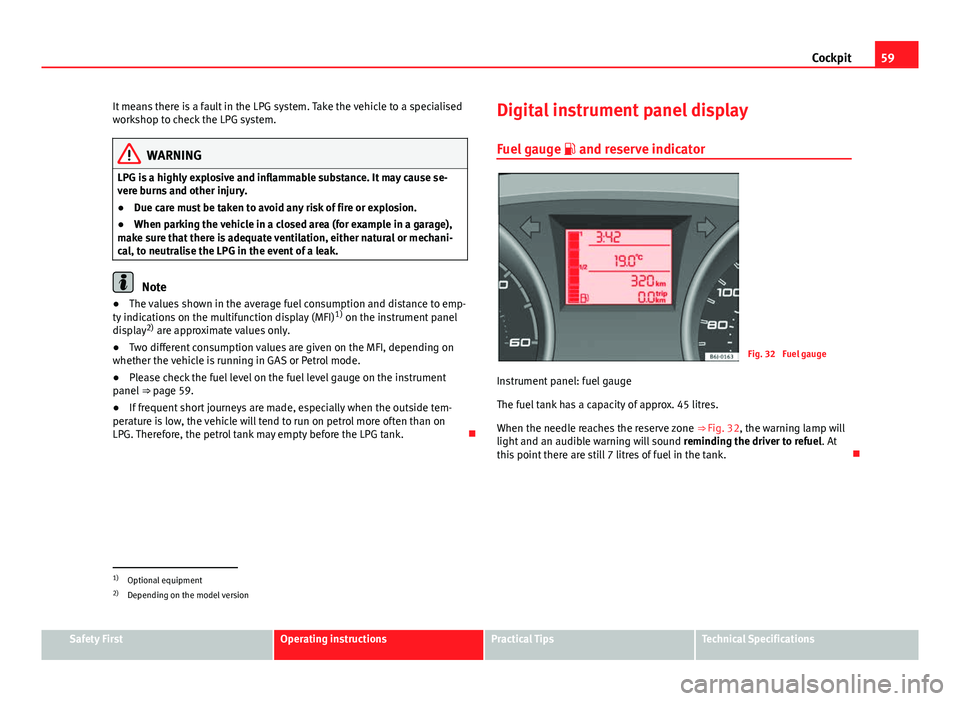
The fuel tank has a capacity of approx. 45 litres.
When the needle reaches the reserve zone ⇒ Fig. 32, the warning lamp will
light and an audible warning will sound reminding the driver to refuel. At
this point there are still 7 litres of fuel in the tank.
1)
Optional equipment
2) Depending on the model version
Safety FirstOperating instructionsPractical TipsTechnical Specifications
Page 144 of 294
142Air conditioning
● The outside temperature is lower than approximately +3 °C (+37 °F).
● The air conditioning system compressor has been temporarily switched
off because of an increased engine coolant temperature.
● The air conditioner fuse is faulty.
● Another fault in the vehicle. Have the air conditioning checked by a spe-
cialised workshop.
Air recirculation
Air recirculation mode prevents fumes or unpleasant smells
from coming from the outside.
When air recirculation mode is switched on (button ⇒ Fig. 106
with
warning lamp) strong odours in the outside air do not enter the vehicle inte-
rior, for example when passing through a tunnel or in a traffic jam.
When the outside temperature is low, air recirculation mode improves heat-
ing performance by heating air from the interior instead of cold air from the
outside.
When the outside temperature is high, air recirculation mode improves cool-
ing performance by cooling air from the interior instead of warm air from
outside.
For safety reasons, the air recirculation should not be switched on when the
air distribution control is set to the windscreen setting .
WARNING
In air recirculation mode, no cold air from the outside enters the vehicle
interior. If the air conditioner is switched off, the windows can quickly
mist over. Therefore, never leave the air recirculation mode switched on
for a long time (risk of accident).
Note
● When engaging reverse gear, the air recirculation is connected automat-
ically to prevent the entrance of exhaust gases in the vehicle on travelling
backwards. The control lamp on the button
does not light up.
● If the temperature control is turned to the coldest setting (blue point)
and the switch AC
is activated, the “Air recirculation” function is automati-
cally activated in order to cool the vehicle rapidly using less energy; its
function control lamp will light.
● If the function is not deactivated by pressing the button, this will deacti-
vate after approx. 20 min.
Economic use of the air conditioning
When the air conditioning is switched on, the compressor consumes engine
power and has influence on fuel consumption. Consider the following
points in order to have the system operating in the minimum possible time.
● If the vehicle interior has overheated due to an excessive solar radiation,
it is best to open the windows or doors to allow the hot air to escape.
● While in motion, the air conditioning should not be switched on if the
windows or the sunroof* are open.
Page 182 of 294
180Driving and the environment
recommend that you have the thickness of your brake pads checked by a
Technical Service more frequently than recommended in the Maintenance
Programme.
If you drive with wet brakes, for example, after crossing areas of water, in
heavy rainfall or even after washing the vehicle, the effect of the brakes is
lessened as the brake discs are wet or even frozen (in winter). In this case
the brakes should be dried by pressing the brake pedal several times.
WARNING
Longer braking distances and faults in the brake system increase the risk
of accidents.
● New brake pads must be run in and do not have the correct friction
during the first 200 km. However, the reduced braking capacity may be
compensated by pressing on the brake pedal a little harder. This also ap-
plies when the brake pads have to be changed further on.
● If brakes are wet or frozen, or if you are driving on roads which have
been salted, braking power may be lower than normal.
● On steep slopes, if brakes are excessively used, they will overheat.
Before driving down a long steep slope, it is advisable to reduce speed
and change down into a lower gear or range (depending on the type of
transmission). This makes use of engine braking and relieves the brakes.
● Never let the brakes “drag” by applying light pressure. Continuous
braking will cause the brakes to overheat and the braking distance will
increase. Apply and then release the brakes alternately.
● Never let the vehicle run with the engine switched off. The braking
distance is increased considerably when the brake servo is not active.
● If the brake fluid loses its viscosity and is subjected to heavy use, va-
pour bubbles can form in the brake system. This reduces the efficiency of
the brakes.
WARNING (Continued)
● Non-standard or damaged front spoilers could restrict the airflow to
the brakes and cause them to overheat. Before purchasing accessories
please observe the relevant instructions ⇒ page 196, Technical modifi-
cations.
● If a brake system circuit fails, the braking distance will be increased
considerably. Contact a specialised workshop immediately and avoid un-
necessary journeys.
Exhaust gas purification system Catalytic converter*
To maintain the useful life of the catalytic converter
– Use only unleaded petrol with petrol engines, as lead damages
the catalytic converter.
– Do not let the fuel get too low in the tank.
– For engine oil changes, do not replenish with too much engine
oil ⇒ page 212, Topping up engine oil .
– Never tow the vehicle to start it, use jump leads if necessary
⇒ page 256.
If you notice misfiring, uneven running or loss of power when the vehicle is
moving, reduce speed immediately and have the vehicle inspected at the
nearest specialised workshop. In general, the exhaust gas warning lamp
will light up when any of the described symptoms occur ⇒ page 65. If this
happens, unburnt fuel can enter the exhaust system and escape into the en-
vironment. The catalytic converter can also be damaged by overheating.
Page 202 of 294
200Checking and refilling levels
Checking and refilling levels
Refuelling
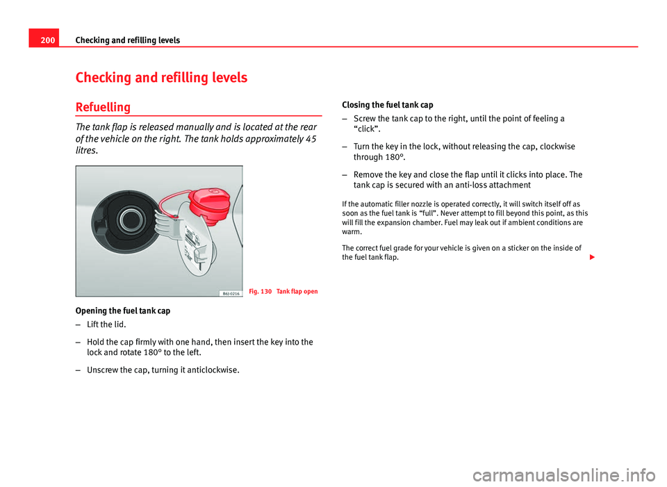
The tank flap is released manually and is located at the rear
of the vehicle on the right. The tank holds approximately 45
litres.
Fig. 130 Tank flap open
Opening the fuel tank cap
– Lift the lid.
– Hold the cap firmly with one hand, then insert the key into the
lock and rotate 180° to the left.
– Unscrew the cap, turning it anticlockwise. Closing the fuel tank cap
–
Screw the tank cap to the right, until the point of feeling a
“click”.
– Turn the key in the lock, without releasing the cap, clockwise
through 180°.
– Remove the key and close the flap until it clicks into place. The
tank cap is secured with an anti-loss attachment
If the automatic filler nozzle is operated correctly, it will switch itself off as
soon as the fuel tank is “full”. Never attempt to fill beyond this point, as this
will fill the expansion chamber. Fuel may leak out if ambient conditions are
warm.
The correct fuel grade for your vehicle is given on a sticker on the inside of
the fuel tank flap.
Page 204 of 294
202Checking and refilling levels
LPG system*
Refuelling with LPG
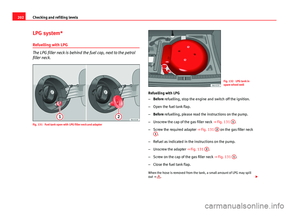
The LPG filler neck is behind the fuel cap, next to the petrol
filler neck.
Fig. 131 Fuel tank open with LPG filler neck and adapter
Fig. 132 LPG tank in
spare wheel well
Refuelling with LPG
– Before refuelling, stop the engine and switch off the ignition.
– Open the fuel tank flap.
– Before refuelling, please read the instructions on the pump.
– Unscrew the cap of the gas filler neck ⇒ Fig. 131 1
.
– Screw the required adapter ⇒ Fig. 131 2
on the gas filler neck
1.
– Refuel as indicated in the instructions on the pump.
– Unscrew the adapter ⇒ Fig. 131 2
.
– Screw on the cap of the gas filler neck ⇒ Fig. 131 1
.
– Close the fuel tank flap.
When the hose is removed from the tank, a small amount of LPG may spill
out ⇒
.
Page 205 of 294
203
Checking and refilling levels
The LPG tank ⇒ Fig. 132 in the spare wheel well has a capacity of 52.8 li-
tres. If the outside temperatures are very low, it may not be possible to com-
pletely fill the LPG tank.
Pump attachments
There are a variety of types of LPG pump, and the methods of use may vary.
Therefore, let the pump operator fill the tank when refuelling for the first
time or fill from another pump.
Noises when refuelling with LPG
When refuelling with LPG, noises may be heard. These noises are insignifi-
cant.
WARNING
Failure to refuel or handle LPG in the correct way could result in a fire,
cause an explosion or lead to injuries.
● LPG is a highly explosive and inflammable substance. It may cause
severe burns and other injury.
● Switch off the engine before refuelling.
● Always switch off mobile phones and any other radiophony applian-
ces, as electromagnetic waves may produce sparks and cause a fire.
● Do not remain in the vehicle while refuelling. If it is absolutely neces-
sary to enter the vehicle, close the door and touch a metal surface before
touching the attachment again. This will prevent the generation of static
electricity and any possible fires while refuelling.
● Small quantities of LPG may leak out after refuelling. If LPG comes in-
to contact with skin, there is a risk of freezing.
● Do not smoke and always keep bare flames away from the tank during
refuelling. Failure to do so may lead to an explosion.
Adapter for the liquid petroleum gas (LPG) filler neck
An adapter is required due to the existence of a range of
pumps with different nozzles.
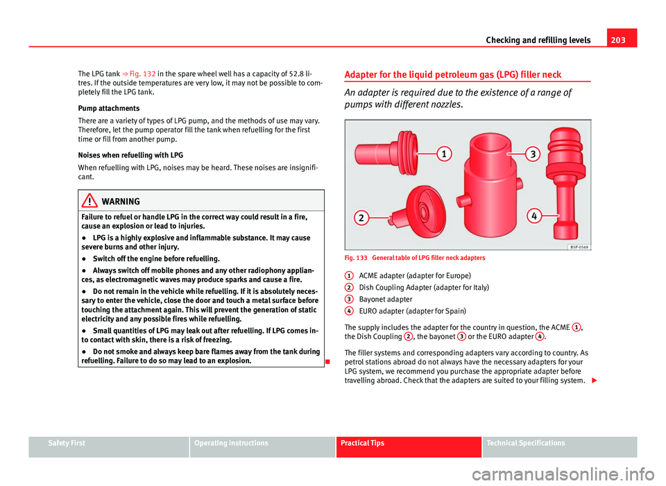
Fig. 133 General table of LPG filler neck adapters
ACME adapter (adapter for Europe)
Dish Coupling Adapter (adapter for Italy)
Bayonet adapter
EURO adapter (adapter for Spain)
The supply includes the adapter for the country in question, the ACME 1
,
the Dish Coupling 2, the bayonet 3 or the EURO adapter 4.
The filler systems and corresponding adapters vary according to country. As
petrol stations abroad do not always have the necessary adapters for your
LPG system, we recommend you purchase the appropriate adapter before
travelling abroad. Check that the adapters are suited to your filling system.
1
234
Safety FirstOperating instructionsPractical TipsTechnical Specifications
Page 209 of 294
207
Checking and refilling levels
6. Raise the bonnet ⇒ page 208.
You should not do any work in the engine compartment unless you know ex-
actly how to carry out the jobs and have the correct tools! Have the work car-
ried out by a specialised workshop if you are uncertain.
All service fluids and consumables, e.g. coolant, engine oil, spark plugs
and batteries, are under constant development. SEAT provides a constant
flow of information to the Technical Services concerning modifications. For
this reason, we recommend you to have service fluids and consumables re-
placed by a Technical Service. Please observe the relevant instructions
⇒ page 196. The engine compartment of the vehicle is a hazardous area
⇒
.
WARNING
All work on the engine or in the engine compartment, e.g. checking and
refilling fluids, involves the danger of injury and scalding as well as the
risk of accident or fire.
● Never open the bonnet if you see steam, smoke or coolant escaping
from the engine compartment. Otherwise, there is a risk of sustaining
burns. Wait until no more steam or coolant is emitted, then allow the en-
gine to cool before carefully opening the bonnet.
● Switch off the engine and remove the key from the ignition.
● Apply the handbrake and move the gear lever to neutral or selector
lever to position P.
● Keep children away from the vehicle.
● Never touch hot engine parts. There is a risk of burns.
● Never spill liquids on a hot engine or on a hot exhaust gas system.
This is a fire hazard.
● Avoid causing short-circuits in the electrical system, particularly at
the points where the jump leads are attached ⇒ page 257. The battery
could explode.
WARNING (Continued)
● Never touch the radiator fan. It is temperature controlled and could
start automatically, even when the engine has been switched off and the
key removed from the ignition!
● Do not unscrew the cap on the coolant expansion tank when the en-
gine is hot. If the coolant is hot, the cooling system will be pressurised!
● Protect face, hands and arms by covering the cap with a large, thick
cloth to protect against escaping coolant and steam.
● Always make sure you have not left any objects, such as cleaning
cloths and tools, in the engine compartment.
● If you have to work underneath the vehicle, you must use suitable
stands additionally to support the vehicle, there is a risk of accident!. A
hydraulic jack is insufficient for securing the vehicle and there is a risk of
injury.
● If any work has to be performed when the engine is started or with
the engine running, there is an additional, potentially fatal, safety risk
from the rotating parts, such as the drive belts, alternator, radiator fan,
etc., and from the high-voltage ignition system. You should also observe
the following points:
–Never touch the electrical wiring of the ignition system.
– Ensure that jewellery, loose clothing and long hair do not get trap-
ped in rotating engine parts. Danger of death. Before starting any
work remove jewellery, tie back and cover hair, and wear tight-fitting
clothes.
– Never accelerate with a gear engaged without taking the necessary
precautions. The vehicle could move, even if the handbrake is ap-
plied. Danger of death.
● If work has to be carried out on the fuel system or on electrical com-
ponents, you must observe the following safety notes in addition to the
above warnings:
–Always disconnect the battery from the on-board network. The ve-
hicle must be unlocked when this is done, otherwise the alarm will be
triggered.
– Do not smoke.
Safety FirstOperating instructionsPractical TipsTechnical Specifications
Page 229 of 294
227
Checking and refilling levels
Winter tyres
Winter tyres will improve the vehicles handling on snow and
ice.
In winter conditions winter tyres will considerably improve the vehicle's han-
dling. The design of summer tyres (width, rubber compound, tread pattern)
gives less grip on ice and snow.
The winter tyres must be inflated to a pressure 0.2 bar (2.9 psi / 20 kPa)
higher than the pressures specified for summer tyres (see sticker on fuel
tank flap) .
Winter tyres must be fitted on all four wheels.
Information on permitted winter tyre sizes can be found in the vehicle's reg-
istration documentation. Use only radial winter tyres. All tyre sizes listed in
the vehicle documentation also apply to winter tyres.
Winter tyres lose their effectiveness when the tread is worn down to a depth
of 4 mm.
The speed rating code ⇒ page 225, New tyres and wheels determines the
following speed limits for winter tyres: ⇒
max. 160 km/h (99 mph)
max. 180 km/h (112 mph)
max. 190 km/h (118 mph)
max. 210 km/h (130 mph)
In some countries, vehicles which can exceed the speed rating of the fitted
tyre must have an appropriate sticker in the driver's field of view. These
stickers are available from your Technical Service. The legal requirements of
each country must be followed.
Do not have winter tyres fitted for unnecessarily long periods. Vehicles with
summer tyres handle better when the roads are free of snow and ice. Q
S
T
H If you have a flat tyre, please refer to the notes on the spare wheel
⇒ page 225, New tyres and wheels.
WARNING
The maximum speed for the winter tyres must not be exceeded. Other-
wise, this could lead to tyre damage and risk of accident.
For the sake of the environment
Fit your summer tyres again as soon as possible. They are quieter, do not
wear so quickly and reduce fuel consumption.
Snow chains
Snow chains may be fitted only to the front wheels, and only for the follow-
ing tyres:
175/70R14
185/60R15Chains with links not exceeding 15 mm (including the chain
closure)
215/45R16Chains with links not exceeding 9 mm (including the chain
closure)
215/40R17Chains with links not exceeding 7 mm (including the chain
closure)
Remove wheel hub covers and trim rings before fitting snow chains. For
safety reasons cover caps, available in any Technical Service, must then be
fitted over the wheel bolts.
WARNING
Snow chains should be correctly tightened in accordance with the manu-
facturer's instructions. This will prevent the chains coming into contact
with the wheel housing.
Safety FirstOperating instructionsPractical TipsTechnical Specifications