oil change Seat Ibiza ST 2015 Owner's manual
[x] Cancel search | Manufacturer: SEAT, Model Year: 2015, Model line: Ibiza ST, Model: Seat Ibiza ST 2015Pages: 248, PDF Size: 4.77 MB
Page 27 of 248
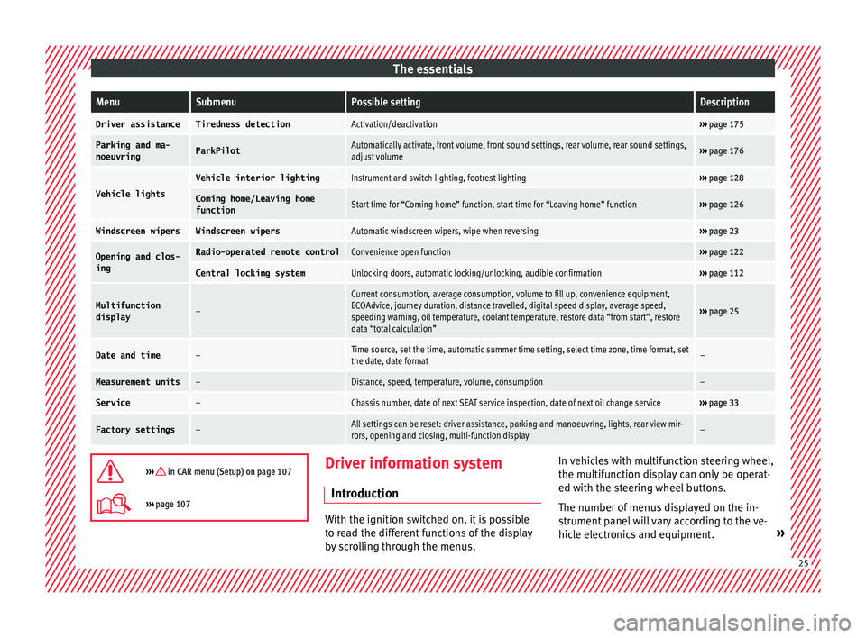
The essentialsMenuSubmenuPossible settingDescription
Driver assistanceTiredness detectionActivation/deactivation›››
page 175
Parking and ma-
noeuvringParkPilotAutomatically activate, front volume, front sound settings, rear volume, rear sound settings,
adjust volume››› page 176
Vehicle lights
Vehicle interior lightingInstrument and switch lighting, footrest lighting››› page 128
Coming home/Leaving home
functionStart time for “Coming home” function, start time for “Leaving home” function››› page 126
Windscreen wipersWindscreen wipersAutomatic windscreen wipers, wipe when reversing››› page 23
Opening and clos-
ingRadio-operated remote controlConvenience open function››› page 122
Central locking systemUnlocking doors, automatic locking/unlocking, audible confirmation››› page 112
Multifunction
display–
Current consumption, average consumption, volume to fill up, convenience equipment,
ECOAdvice, journey duration, distance travelled, digital speed display, average speed,
speeding warning, oil temperature, coolant temperature, restore data “from start”, restore
data “total calculation”
››› page 25
Date and time–Time source, set the time, automatic summer time setting, select time zone, time format, set
the date, date format–
Measurement units–Distance, speed, temperature, volume, consumption–
Service–Chassis number, date of next SEAT service inspection, date of next oil change service››› page 33
Factory settings–All settings can be reset: driver assistance, parking and manoeuvring, lights, rear view mir-
rors, opening and closing, multi-function display–
››› in CAR menu (Setup) on page 107
›››
page 107 Driver information system
Intr oduction With the ignition switched on, it is possible
to r
e
ad the different functions of the display
by scrolling through the menus. In vehicles with multifunction steering wheel,
the multif
u
nction display can only be operat-
ed with the steering wheel buttons.
The number of menus displayed on the in-
strument panel will vary according to the ve-
hicle electronics and equipment. » 25
Page 35 of 248
The essentials
on the instrument panel, as well as a mes-
s ag
e f
or the driver: speed warning ex-
ceeded! The warning lamp switches off
when reducing speed below the stored maxi-
mum limit.
Speed warning programming is recommen-
ded if you wish to be reminded of a maxi-
mum speed, such as when travelling in a
country with different speed limits or for a
maximum speed for winter tyres.
Setting speed limit warning
You can use the radio or the Easy Connect* to
set, alter or cancel the speed limit warning.
● Vehicles with radio : pres
s the button SETUP> control button Driver Assistant
>
Speed warning .
● Vehicles with Easy Connect : pre
s
s the but-
ton Systems or else Vehicle systems >
Driver assistant > Speed warning.
The warning limit can be set from 30 to
240 km/h (20 to 150 mph). The adjustment
is done in 10 km/h (mph) intervals. Note
● Ple a
se bear in mind that, even with the
speed warning function, it is still important
to keep an eye on the vehicle speed with the
speedometer and to observe the legal speed
limits. ●
The speed limit w
arning function in the ver-
sion for several countries warns you at a
speed of 120 km/h (80 mph). This is a facto-
ry-set speed limit. Service intervals
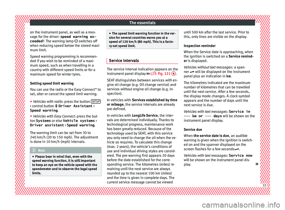
The service interval indication appears on the
ins
trument
panel display ›››
Fig. 121
4 .
SEA T di
stinguishes between services with en-
gine oil change (e.g. Oil change service) and
services without engine oil change (e.g. In-
spection).
In vehicles with Services established by time
or mileage, the service intervals are already
pre-defined.
In vehicles with LongLife Service , the inter-
vals are determined individually. Thanks to
technological progress, maintenance work
has been greatly reduced. Because of the
technology used by SEAT, with this service
you only need to change the oil when the ve-
hicle so requires. To calculate this change
(max. 2 years), the vehicle's conditions of
use and individual driving styles are consid-
ered. The pre-warning first appears 20 days
before the date established for the corre-
sponding service. The kilometres (miles) re-
maining until the next service are always
rounded up to the nearest 100 km (miles)
and the time is given in complete days. The
current service message cannot be viewed until 500 km after the last service. Prior to
this, on
ly
lines are visible on the display.
Inspection reminder
When the Service date is approaching, when
the ignition is switched on a Service remind-
er is displayed.
Vehicles without text messages : a span-
ner will be displayed on the instrument
panel plus an indication in km.
The kilometres indicated are the maximum
number of kilometres that can be travelled
until the next service. After a few seconds,
the display mode changes. A clock symbol
appears and the number of days until the
next service is due.
Vehicles with text messages : Service in
--- km or --- days will be shown on the
instrument panel display.
Service due
When the service date is due , an audible
warning is given when the ignition is switch-
ed on and the spanner displayed on the
screen flashes for a few seconds .
Vehicles with text messages : Service now
will be shown on the instrument panel dis-
play. » 33
Page 85 of 248
Fuses and bulbs
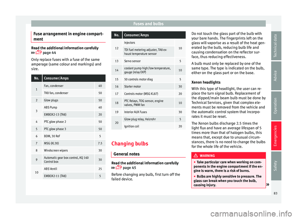
Fuse arrangement in engine compart-
ment Read the additional information carefully
›› ›
page 44
Only replace fuses with a fuse of the same
amperage (same colour and markings) and
size.
No.Consumer/Amps
1Fan, condenser40
TK8 fan, condenser50
2Glow plugs50
3ABS Pump40
EMBOX2-13 (TA8)20
4PTC glow phase 250
5PTC glow phase 350
6BDM, 30 ReF5
7MSG (KL30)7.5
8Windscreen wipers30
9Automatic gear box control, AQ 160
Control box30
10ABS Ventil25
EMBOX2-11 (TA8)5
No.Consumer/Amps
12
Injectors
10TDI fuel metering adjuster, TA8 ex-
haust temperature sensor
13Servo sensor5
14coolant pump high/low temperature,
gauge (relay EKP)10
1550 controls motor diag5
16Starter motor30
17Controls motor (MSG KL87)20
18PTC Relays, TOG sensor, engine
valves, PWM fan10
19Interior AUX Fuses30
20Glow plug relay, Heizrohr5
Ignition coil20 Changing bulbs
Gener al
notes Read the additional information carefully
› ›
›
page 45
Before changing any bulb, first turn off the
failed device. Do not touch the glass part of the bulb with
your bar
e hands. The fingerprints left on the
glass will vaporise as a result of the heat gen-
erated by the bulb, reducing bulb life and
causing condensation on the reflector sur-
face, thus reducing effectiveness.
A bulb must only be replaced by one of the
same type. The type is indicated on the bulb,
either on the glass part or on the base.
Xenon headlights
With this type of headlight, the user can re-
place the turn signal bulb. Replacement of
the dipped/main beam bulb must be done by
Technical Services, given that complex ele-
ments must be removed from the vehicle and
the automatic control system that incorpo-
rates it must be reset.
The Xenon bulbs discharge 2.5 times the
light flux and have an average lifespan of 5
times more than that of halogen bulbs, this
means that, except due to unusual circum-
stances, there is no need to change the bulbs
for the whole life of the vehicle. WARNING
● Tak e p
articular care when working on com-
ponents in the engine compartment if the en-
gine is warm, there is a risk of burns.
● Bulbs are highly sensitive to pressure. The
glas
s can break when you touch the bulb,
causing injury. » 83
Technical data
Advice
Operation
Emergencies
Safety
Page 101 of 248
Instruments and warning/control lamps
●
Dependin g on the equipment, some set
-
tings and instructions can also be carried out
in the Easy Connect system.
● When several warnings are active at the
same time, the symbol
s are shown succes-
sively for a few seconds and will stay on until
the fault is rectified. Odometer
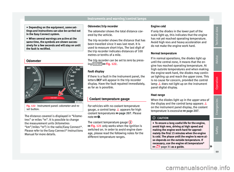
Fig. 122
Instrument panel: odometer and re-
set b
utt
on. The distance covered is displayed in “kilome-
tr
e
s” or mi
les “m”. It is possible to change
the measurement units (kilometres
“km”/miles “m”) in the radio/Easy Connect*.
Please refer to the Easy Connect* Instructions
Manual for more details. Odometer/trip recorder
The odometer show
s the total distance cov-
ered by the vehicle.
The trip recorder shows the distance that has
been travelled since it was last reset. It is
used to measure short trips. The last digit of
the trip recorder indicates distances of 100
metres or tenths of a mile.
The trip recorder can be set to zero by press-
ing 0.0/SET
› ››
Fig. 122
.
F
ault display
If there is a fault in the instrument panel, the
letters DEF will appear in the trip recorder
display. Have the fault repaired immediately,
as far as is possible.
Coolant temperature gauge For vehicles with no coolant temperature
g
aug
e, a c
ontrol lamp appears for high
coolant temperatures ›››
page 207. Please
note ››› .
The c oo
l
ant temperature gauge 2 ›››
Fig. 121 only w
orks when the ignition is
switched on. In order to avoid engine dam-
age, please read the following notes for the
different temperature ranges. Engine cold
If on
ly
the diodes in the lower part of the
scale light up, this indicates that the engine
has not yet reached operating temperature.
Avoid high revs and heavy acceleration and
do not make the engine work hard.
Normal temperature
If in normal operations, the diodes light up
until the central zone, it means that the en-
gine has reached operating temperature. At
high outside temperatures and when making
the engine work hard, the diodes may contin-
ue lighting up and reach the upper zone. This
is no cause for concern, provided the control
lamp does not light up on the instrument
panel digital display.
Heat range
When the diodes light up in the upper area of
the display and the control lamp appears
on the instrument panel display, the coolant
temperature is excessive ››› page 207. CAUTION
● To en s
ure a long useful life for the engine,
avoid high revs, driving at high speed and
making the engine work hard for approxi-
mately the first 15 minutes when the engine
is cold. The phase until the engine is warm al-
so depends on the outside temperature. If
necessary, use the engine oil temperature*
››› page 31 as a guide. » 99
Technical data
Advice
Operation
Emergencies
Safety
Page 168 of 248
Operation
● Use of
so
lvent-free adhesives.
● Use of CFC-free coolants in cooling sys-
tems.
● Recy
cling and energy recovery from resi-
dues (RDF).
● Impr
ovement in the quality of waste water.
● Use of systems for the recovery of residual
heat (therm
al recovery, enthalpy wheels,
etc.).
● The use of water-soluble paints.
Catalytic converter To maintain the useful life of the catalytic
c
on
v
erter
– Use only unleaded petrol with petrol en-
gines, as
lead damages the catalytic con-
verter.
– Do not let the fuel get too low in the tank.
– For engine oil changes, do not replenish
with too muc
h engine oil ›››
page 206, Top-
ping up engine oil.
– Never tow the vehicle to start it, use jump
lea
ds if necessary ›››
page 52.
If you notice misfiring, uneven running or
loss of power when the vehicle is moving, re-
duce speed immediately and have the vehi-
cle inspected at the nearest specialised
workshop. In general, the exhaust warning lamp will light up when any of the described
symptoms oc
cur ››› page 100. If this hap-
pens, unburnt fuel can enter the exhaust sys-
tem and escape into the environment. The
catalytic converter can also be damaged by
overheating. WARNING
The catalytic converter reaches very high
temper at
ures! Risk of fire!
● Never park where the catalytic converter
coul
d come into contact with dry grass or
flammable materials under the vehicle.
● Do not apply additional underseal or anti-
corro
sion coatings to the exhaust pipes, cata-
lytic converter or the heat shields on the ex-
haust system. These materials could catch
fire when the vehicle is being driven. CAUTION
Never run the fuel tank completely dry be-
cau se the irr
egularity of the fuel supply may
cause ignition problems. This allows unburnt
fuel to enter the exhaust system, which could
cause overheating and damage the catalytic
converter. For the sake of the environment
Even when the emission control system is
work in
g perfectly, there may be a smell of
sulphur from the exhaust gas under some
conditions. This depends on the sulphur con-
tent of the fuel used. Quite often the problem can be solved by changing to another brand
of f
uel
. Diesel engine particulate filter*
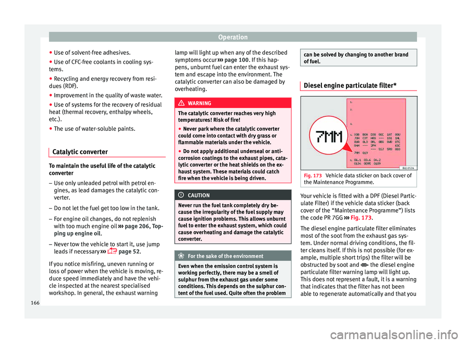
Fig. 173
Vehicle data sticker on back cover of
the M aint
en
ance Programme. Your vehicle is fitted with a DPF (Diesel Partic-
u
l
at
e Filter) if the vehicle data sticker (back
cover of the “Maintenance Programme”) lists
the code PR 7GG ››› Fig. 173.
The diesel engine particulate filter eliminates
most of the soot from the exhaust gas sys-
tem. Under normal driving conditions, the fil-
ter cleans itself. If this is not possible (for ex-
ample, multiple short trips) the filter will be
obstructed by soot and the diesel engine
particulate filter warning lamp will light up.
This does not represent a fault, it is a warning
that indicates that the filter has not been
able to regenerate automatically and that you
166
Page 207 of 248
Checking and refilling levels
The specifications (VW standards) set out in
the f o
l
lowing page should appear on the con-
tainer of the service oil; when the container
displays the specific standards for petrol and
diesel engines together, it means that the oil
can be used for both types of engines.
We recommend that the oil change indicated
in the Maintenance Programme, be per-
formed by a technical service or specialised
workshop.
The correct oil specifications for your engine
are listed in the ›››
page 41.
Service intervals
Service intervals can be flexible (LongLife
service) or fixed (dependent on time/dis-
tance travelled).
If the PR code that appears on the back of the
Maintenance Programme booklet is PR QI6,
this means that your vehicle has the LongLife
service program. If it lists the codes QI1, QI2,
QI3, QI4 or QI7, the interval service is de-
pendent on the time/distance travelled.
Flexible service intervals (LongLife service
intervals*)
Special oils and processes have been devel-
oped which, depending on the characteris-
tics and individual driving profiles, enable
the extension of the oil change service (Long-
Life service intervals). Because this oil is essential for extending the
servic
e intervals, it must only be used ob-
serving the following indications:
● Avoid mixing it with oil for fixed service in-
terv
als.
● Only in exceptional circumstances, if the
engine oil
level is too low ››› page 206 and
LongLife oil is not available, it is permitted to
top up (once) with oil for fixed service inter-
vals ›››
page 41 (up to a maximum of 0.5
litres).
Fixed service intervals*
If your vehicle does not have the “LongLife
service interval” or it has been disabled (by
request), you may use oils for fixed service
intervals, which also appear in
››› page 41. In this case, your vehicle
must be serviced after a fixed interval of 1
year/15,000 km (10,000 miles)(whatever
comes first) ››› Booklet Maintenance Pro-
gramme.
● In exceptional circumstances, if the engine
oil l
evel is too low ››› page 206 and you can-
not obtain the oil specified for your vehicle,
you can add a small quantity of oil conform-
ing to the specification ACEA A2 or ACEA A3
(petrol engines) or ACEA B3 or ACEA B4 (die-
sel engines) (up to 0.5 l). Vehicles with diesel particulate filter*
The Mainten
ance Programme states whether
your vehicle is fitted with a diesel particulate
filter.
Only VW 507 00 engine oil, with reduced ash
formation, may be used in diesel engines
equipped with particulate filter. Using other
types of oil will cause a higher soot concen-
tration and reduce the life of the DPF. There-
fore:
● Avoid mixing this oil with other engine oils.
● Only in exceptional circumstances, if the
engine oil
level is too low ››› page 206 and
you cannot obtain the oil specified for your
vehicle, you can use a small quantity of oil
(once) conforming to the VW 506 00,
VW 506 01, VW 505 00, VW 505 01 or
ACEA B3/ACEA B4 specification. (up to 0.5 l). Note
Before a long trip, we recommend finding an
engine oi l
that conforms to the correspond-
ing VW specifications and recommend keep-
ing it in the vehicle. This way, the correct en-
gine oil will always be available for a top-up if
needed. 205
Technical data
Advice
Operation
Emergencies
Safety
Page 208 of 248
Advice
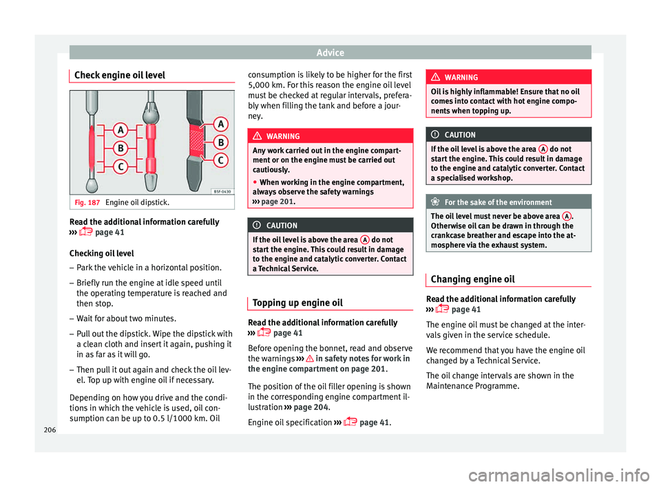
Check engine oil level Fig. 187
Engine oil dipstick. Read the additional information carefully
› ›
›
page 41
Checking oil level
– Park the vehicle in a horizontal position.
– Briefly run the engine at idle speed until
the operating t
emperature is reached and
then stop.
– Wait for about two minutes.
– Pull out the dipstick. Wipe the dipstick with
a cle
an cloth and insert it again, pushing it
in as far as it will go.
– Then pull it out again and check the oil lev-
el. T
op up with engine oil if necessary.
Depending on how you drive and the condi-
tions in which the vehicle is used, oil con-
sumption can be up to 0.5 l/1000 km. Oil consumption is likely to be higher for the first
5,000 km. For this
reason the engine oil level
must be checked at regular intervals, prefera-
bly when filling the tank and before a jour-
ney. WARNING
Any work carried out in the engine compart-
ment or on the en gine mu
st be carried out
cautiously.
● When working in the engine compartment,
alwa
ys observe the safety warnings
››› page 201. CAUTION
If the oil level is above the area A do not
st ar
t the engine. This could result in damage
to the engine and catalytic converter. Contact
a Technical Service. Topping up engine oil
Read the additional information carefully
› ›
›
page 41
Before opening the bonnet, read and observe
the warnings ››› in safety notes for work in
the en gine c
omp
artment on page 201.
The position of the oil filler opening is shown
in the corresponding engine compartment il-
lustration ›››
page 204.
Engine oil specification ›››
page 41. WARNING
Oil is highly inflammable! Ensure that no oil
come s
into contact with hot engine compo-
nents when topping up. CAUTION
If the oil level is above the area A do not
st ar
t the engine. This could result in damage
to the engine and catalytic converter. Contact
a specialised workshop. For the sake of the environment
The oil level must never be above area A .
Otherw i
se oil can be drawn in through the
crankcase breather and escape into the at-
mosphere via the exhaust system. Changing engine oil
Read the additional information carefully
› ›
›
page 41
The engine oil must be changed at the inter-
vals given in the service schedule.
We recommend that you have the engine oil
changed by a Technical Service.
The oil change intervals are shown in the
Maintenance Programme.
206
Page 209 of 248
Checking and refilling levels
WARNING
Only change the engine oil yourself if you
hav e the s
pecialist knowledge required!
● Before opening the bonnet, read and ob-
serve the w
arnings ››› page 201, safety notes
for work in the engine compartment .
● Wait for the engine to cool down. Hot oil
may
cause burn injuries.
● Wear eye protection to avoid injuries, such
as ac
id burns, caused by splashes of oil.
● When removing the oil drain plug with your
finger
s, keep your arm horizontal to help pre-
vent oil from running down your arm.
● Wash your skin thoroughly if it comes into
contact
with engine oil.
● Engine oil is poisonous! Used oil must be
stor
ed in a safe place out of the reach of chil-
dren. CAUTION
No additives should be used with engine oil.
This c
ould result in engine damage. Any dam-
age caused by the use of such additives
would not be covered by the factory warranty. For the sake of the environment
● Bec au
se of disposal problems and the spe-
cial tools and specialist knowledge required,
we recommend that you have the engine oil
and filter changed by a Technical Service. ●
Never pour oi l
down drains or into the
ground.
● Use a suitable container when draining the
used oil
. It must be large enough to hold all
the engine oil. Cooling system
Top pin
g up coolant Read the additional information carefully
› ›
›
page 42
Top up coolant when the level is below the
MIN (minimum) mark.
Checking coolant level
– Park the vehicle in a horizontal position.
– Switch the ignition off.
– Read off the coolant level on coolant ex-
pans
ion tank. When the engine is cold, the
coolant level should be between the marks.
When the engine is hot, it may be slightly
above the upper mark.
Topping up coolant
– Wait for the engine to cool down.
– Cover the coolant expansion tank cap with
a cloth and car
efully unscrew it to the left
››› .–
Top up the c
oo
lant only if there is still cool-
ant in the expansion tank, otherwise you could damage the engine. If there is no
coolant in the expansion tank, do not con-
tinue driving. You should obtain professio- nal assistance ››› .
– If there is still some coolant in the expan-
sion t
ank, t
op up to the upper mark.
– Top up with coolant until the level becomes
stab
le.
– Screw the cap back on correctly.
Any lo
ss of coolant fluid normally indicates a
leak in the cooling system. Take the vehicle
straight to a specialised workshop to have
the cooling system examined. If there are no
leaks in the engine cooling system, a loss of
coolant can only occur if the coolant boils
and is forced out of the system as a result of
overheating. WARNING
● The coo lin
g system is under pressure. Do
not unscrew the cap on the coolant expan-
sion tank when the engine is hot: risk of
burns!
● The antifreeze and coolant fluid can be a
health h
azard. Therefore, the antifreeze
should be stored in the original container in a
safe place out of reach of children. Failure to
comply could result in poisoning. » 207
Technical data
Advice
Operation
Emergencies
Safety
Page 210 of 248
Advice
●
If w ork
ing inside the engine compartment,
remember that, even when the ignition is
switched off, the radiator fan may start up au-
tomatically, and therefore there is a risk of in-
jury. WARNING
If there is not enough anti-freeze in the cool-
ant sys
tem, the engine may fail leading to se-
rious damage.
● Please make sure that the percentage of
additiv
e is correct with respect to the lowest
expected ambient temperature in the zone in
which the vehicle is to be used.
● When the outside temperature is very low,
the cool
ant could freeze and the vehicle
would be immobilised. In this case, the heat-
ing would not work either and inadequately
dressed passengers could die of cold. CAUTION
Do not top up the expansion tank with cool-
ant fluid if it
is empty! Air could enter the
cooling system. In this case, stop driving.
Seek specialist assistance. Otherwise, there
is a risk of engine damage. CAUTION
The original additives should never be mixed
with c oo
lants which are not approved by
SEAT. Otherwise, you run the risk of causing severe damage to the engine and the engine
coo
lin
g system.
● If the fluid in the expansion tank is not pur-
ple b
ut is, for example, brown, this indicates
that the G13 additive has been mixed with an
inadequate coolant. The coolant must be
changed as soon as possible if this is the
case! This could result in serious faults and
engine damage. For the sake of the environment
Coolants and additives can contaminate the
en vir
onment. If any fluids are spilled, they
should be collected and correctly disposed
of, with respect to the environment. Brake fluid
Chec k
in
g the brake fluid level Read the additional information carefully
› ›
›
page 43
The position of the brake fluid reservoir is
shown in the corresponding engine compart-
ment illustration ››› page 204. The brake fluid
reservoir has a black and yellow cap.
The brake fluid level drops slightly when the
vehicle is being used as the brake pads are
automatically adjusted as they wear. However, if the level goes down noticeably in
a short time, or dr
ops below the “MIN” mark,
there may be a leak in the brake system. A
display on the instrument panel will warn you
if the brake fluid level is too low ››› page 100. WARNING
Before opening the bonnet to check the brake
fluid lev el, r
ead and observe the warnings
››› page 201. Changing the brake fluid
The Maintenance Programme indicates brake
fluid c
h
an
ge intervals.
We recommend that you have the brake fluid
changed by a Technical Service.
Before opening the bonnet, please read and
follow the warnings ››› in safety notes for
w ork
in the en
gine compartment on
page 201 in section “Safety notes for work-
ing in the engine compartment”.
In the course of time, brake fluid becomes
hygroscopic and absorbs water from the am-
bient air. If the water content in the brake flu-
id is too high, the brake system could cor-
rode. This also considerably reduces the boil-
ing point of the brake fluid. Heavy use of the
brakes may then cause a vapour lock which
could impair the braking effect.
208
Page 239 of 248
Index
Convenience closing tiltin
g p
anoramic sunroof . . . . . . . . . . . . . . . . 123
windows . . . . . . . . . . . . . . . . . . . . . . . . . . . . . . 122
Convenience opening windows . . . . . . . . . . . . . . . . . . . . . . . . . . . . . . 122
Coolant checking level . . . . . . . . . . . . . . . . . . . . . . . . . . 207
Coolant level control lamp . . . . . . . . . . . . . . . . . . . . . . . . . . . 106
Coolant temperature control lamp . . . . . . . . . . . . . . . . . . . . . . . . . . . 106
Safety instructions . . . . . . . . . . . . . . . . . . . . . . 106
Cooling system checking coolant . . . . . . . . . . . . . . . . . . . . . . . 207
Coolant temperature gauge . . . . . . . . . . . . . . . . 99
topping up coolant . . . . . . . . . . . . . . . . . . . . . . 207
Correct position . . . . . . . . . . . . . . . . . . . . . . . . . . . 57
Correct sitting position front passenger . . . . . . . . . . . . . . . . . . . . . . . . . 58
rear seat passengers . . . . . . . . . . . . . . . . . . . . . 59
Cruise control . . . . . . . . . . . . . . . . . . . . . . . . 34, 184 adjusting the stored speed . . . . . . . . . . . . . . . 184
complete deactivation . . . . . . . . . . . . . . . . . . . 185
control lamp . . . . . . . . . . . . . . . . . . . . . . . . . . . 184
temporary deactivation . . . . . . . . . . . . . . . . . . 185
Cruise control system control lamp . . . . . . . . . . . . . . . . . . . . . . . . . . . 104
Cruise speed control lamp . . . . . . . . . . . . . . . . . . . . . . . . . . . 104
Current . . . . . . . . . . . . . . . . . . . . . . . . . . . . . . . . . 138
D Dangers in not using the seat belt . . . . . . . . . . . . 63
Dash panel . . . . . . . . . . . . . . . . . . . . . . . . . . . . . . . 35
Data sticker . . . . . . . . . . . . . . . . . . . . . . . . . . . . . . 217
Deactivating the front passenger front airbag . . . 14
Deactivation of front airbag . . . . . . . . . . . . . . . . . . 70 Diesel . . . . . . . . . . . . . . . . . . . . . . . . . . . . . . . . . . 200
Diesel en
gine
Winter operation . . . . . . . . . . . . . . . . . . . . . . . . 201
Diesel engine particulate filter . . . . . . . . . . . . . . 166
Differential lock fault (EDS) control lamp . . . . . . . . . . . . . . . . . . . . . . . . . . . 103
Digital clock . . . . . . . . . . . . . . . . . . . . . . . . . . . . . . 96
Dimensions . . . . . . . . . . . . . . . . . . . . . . . . . . . . . . 233
Direction of rotation tyres . . . . . . . . . . . . . . . . . . . . . . . . . . . . . . . . . . . 49
Display . . . . . . . . . . . . . . . . . . . . . . . . . . . . . . . 96, 97
Disposal Seat belt tensioners . . . . . . . . . . . . . . . . . . . . . . 66
Door handle de-icing . . . . . . . . . . . . . . . . . . . . . . . . . . . . . . . 195
Door lock de-icing . . . . . . . . . . . . . . . . . . . . . . . . . . . . . . . 195
Door lock cylinder de-icing . . . . . . . . . . . . . . . . . . . . . . . . . . . . . . . 195
Door release lever . . . . . . . . . . . . . . . . . . . . . . . . . 95
Doors Childproof locks . . . . . . . . . . . . . . . . . . . . . . . . 115
opening and closing . . . . . . . . . . . . . . . . . . . . . . 9
Double headlight bulbs . . . . . . . . . . . . . . . . . . . . . 85
Driver see Correct sitting position . . . . . . . . . 57, 58, 59
Driver information system additional electrical appliances . . . . . . . . . . . . 31
assist systems . . . . . . . . . . . . . . . . . . . . . . . . . . 29
bonnet, rear lid and doors open . . . . . . . . . . . . 28
engine oil temperature . . . . . . . . . . . . . . . . . . . . 31
gear-change indicator . . . . . . . . . . . . . . . . . . . . 28
journey data . . . . . . . . . . . . . . . . . . . . . . . . . . . . 29
menu . . . . . . . . . . . . . . . . . . . . . . . . . . . . . . . . . . 27
operation . . . . . . . . . . . . . . . . . . . . . . . . . . . . . . . 25
outside temperature . . . . . . . . . . . . . . . . . . . . . . 27
saving tips . . . . . . . . . . . . . . . . . . . . . . . . . . . . . . 31 service intervals . . . . . . . . . . . . . . . . . . . . . . . . . 33
speed warnin
g . . . . . . . . . . . . . . . . . . . . . . . . . . 32
timer . . . . . . . . . . . . . . . . . . . . . . . . . . . . . . . . . . 31
warning and information messages . . . . . . . . . 29
Driving driving abroad . . . . . . . . . . . . . . . . . . . . . . . . . 168
with a trailer . . . . . . . . . . . . . . . . . . 187, 188, 219
Driving abroad Headlights . . . . . . . . . . . . . . . . . . . . . . . . . . . . 169
petrol . . . . . . . . . . . . . . . . . . . . . . . . . . . . . . . . . 168
Driving assistance systems cruise control . . . . . . . . . . . . . . . . . . . . . . . . . . 184
Driving safety . . . . . . . . . . . . . . . . . . . . . . . . . . . . . 56
Driving with a trailer . . . . . . . . . . . . . . . . . . . . . . . 187
DSG . . . . . . . . . . . . . . . . . . . . . . . . . . . . . . . . . . . . 159
Duplicate keys . . . . . . . . . . . . . . . . . . . . . . . . . . . 116
Dust and pollen filter . . . . . . . . . . . . . . . . . . . . . . 144
Dynamic headlight range control . . . . . . . . . . . . 125
E
Easy Connect . . . . . . . . . . . . . . . . . . . . . . . . 24, 107
Economic driving . . . . . . . . . . . . . . . . . . . . . . . . . . . . . . . . 167
EDL see Electronic differential lock . . . . . . . . . . . . . 170
EDS . . . . . . . . . . . . . . . . . . . . . . . . . . . . . . . . . . . . 170
Efficiency programme additional electrical appliances . . . . . . . . . . . . 31
saving tips . . . . . . . . . . . . . . . . . . . . . . . . . . . . . . 31
Electrical power socket . . . . . . . . . . . . . . . . . . . . 138
Electric windows . . . . . . . . . . . . . . . . . . . . . . 11, 120 convenience opening/closing . . . . . . . . . . . . . 122
Electrolyte . . . . . . . . . . . . . . . . . . . . . . . . . . . . . . . 210
Electronic differential lock . . . . . . . . . 103, 169, 170 control lamp . . . . . . . . . . . . . . . . . . . . . . 102, 103
Electronic differential lock (XDS) . . . . . . . . . . . . . 173
Electronic immobiliser . . . . . . . . . . . . . . . . 107, 154
237