clutch Seat Ibiza ST 2016 Owner's manual
[x] Cancel search | Manufacturer: SEAT, Model Year: 2016, Model line: Ibiza ST, Model: Seat Ibiza ST 2016Pages: 252, PDF Size: 5.56 MB
Page 23 of 252
The essentials
● Pu
sh the loc k
and release it from the an-
choring support.
››› in Safety instructions on page 73 Starting the vehicle
Ignition lock Fig. 29
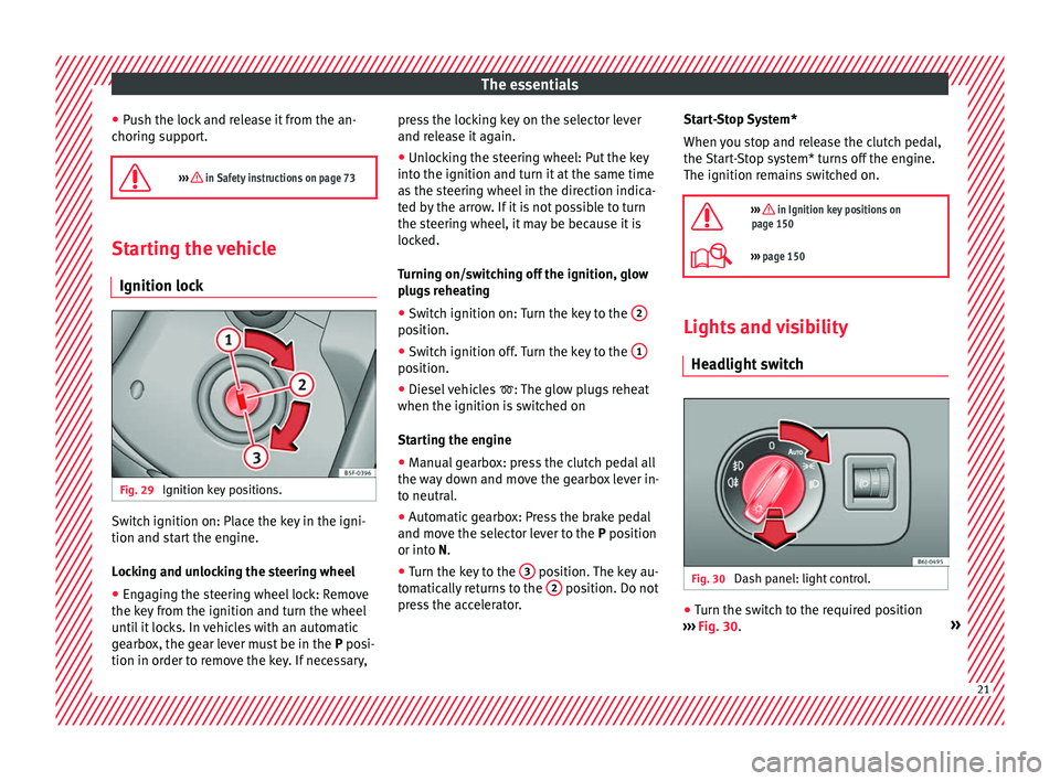
Ignition key positions. Switch ignition on: Place the key in the igni-
tion and s
t
ar t
the engine.
Locking and unlocking the steering wheel
● Engaging the steering wheel lock: Remove
the key from the ignition and t
urn the wheel
until it locks. In vehicles with an automatic
gearbox, the gear lever must be in the P posi-
tion in order to remove the key. If necessary, press the locking key on the selector lever
and relea
se it again.
● Unlocking the steering wheel: Put the key
into the ignition and turn it at
the same time
as the steering wheel in the direction indica-
ted by the arrow. If it is not possible to turn
the steering wheel, it may be because it is
locked.
Turning on/switching off the ignition, glow
plugs reheating
● Switch ignition on: Turn the key to the 2 position.
●
Switch ignition off. Turn the key to the 1 position.
●
Diesel vehicles : The glo
w plug
s reheat
when the ignition is switched on
Starting the engine
● Manual gearbox: press the clutch pedal all
the way do
wn and move the gearbox lever in-
to neutral.
● Automatic gearbox: Press the brake pedal
and move the select
or lever to the P position
or into N.
● Turn the key to the 3 position. The key au-
t om
atic al
ly returns to the 2 position. Do not
pr e
ss
the accelerator. Start-Stop System*
When you st
op and release the clutch pedal,
the Start-Stop system* turns off the engine.
The ignition remains switched on.
››› in Ignition key positions on
page 150
››› page 150 Lights and visibility
He a
dlight sw
itch Fig. 30
Dash panel: light control. ●
Turn the switch to the required position
› ›
›
Fig. 30
. » 21
Page 30 of 252
The essentials
Gear-change indicator Fig. 39
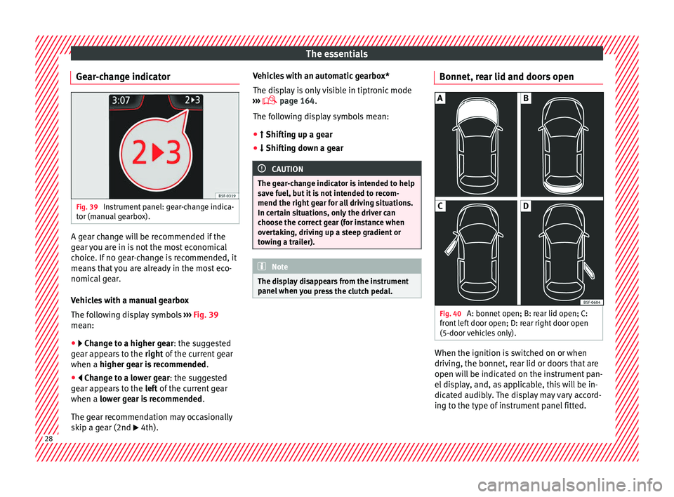
Instrument panel: gear-change indica-
t or (m
anual g
earbox). A gear change will be recommended if the
g
e
ar y
ou are in is not the most economical
choice. If no gear-change is recommended, it
means that you are already in the most eco-
nomical gear.
Vehicles with a manual gearbox
The following display symbols ››› Fig. 39
mean:
● Change to a higher gear: the suggested
g e
ar appears to the right of the current gear
when a higher gear is recommended .
● Change to a lower gear: the suggested
ge
ar appears to the left of the current gear
when a lower gear is recommended .
The gear recommendation may occasionally
skip a gear (2nd 4th). Vehicles with an automatic gearbox*
The disp
l
ay is only visible in tiptronic mode
››› page 164.
The following display symbols mean:
● Shifting up a gear
● Shif
ting down a gear CAUTION
The gear-change indicator is intended to help
save f uel, b
ut it is not intended to recom-
mend the right gear for all driving situations.
In certain situations, only the driver can
choose the correct gear (for instance when
overtaking, driving up a steep gradient or
towing a trailer). Note
The display disappears from the instrument
panel when y
ou press the clutch pedal. Bonnet, rear lid and doors open
Fig. 40
A: bonnet open; B: rear lid open; C:
fr ont
lef
t door open; D: rear right door open
(5-door vehicles only). When the ignition is switched on or when
driv
in
g, the bonnet, r e
ar lid or doors that are
open will be indicated on the instrument pan-
el display, and, as applicable, this will be in-
dicated audibly. The display may vary accord-
ing to the type of instrument panel fitted. 28
Page 39 of 252
The essentials
Fault in the battery.›››
page
210
Driving light totally or partially
faulty.›››
page
83
Fault in the cornering light sys-
tem.››› page
118
Diesel particulate filter blocked›››
page
170
Level of windscreen washer fluid
too low.›››
page
210
Flashing: Fault in the oil level de-
tection. Control manually.›››
page
204
Ignition: Insufficient engine oil.
Fault in the gearbox.›››
page
166
Immobiliser active.›››
page
150
Service interval display›››
page
33
Mobile telephone is connected
via Bluetooth to the original tele-
phone device.›››
Book-
let Radio
or
››› Book-
let Navi-
gation
system
Mobile telephone battery charge
meter. Available only for devices
pre-installed in factory.
Freezing warning. The outside
temperature is lower than +4 °C
(+39 °F).›››
page
27
Start-Stop system activated.›››
page
172
Start-Stop system unavailable.
Low consumption driving status›››
page
27 On the instrument panel
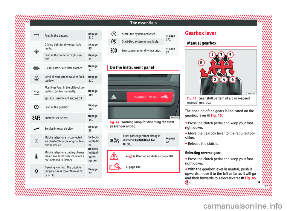
Fig. 44
Warning lamp for disabling the front
p a
ssen
ger airbag.
Front passenger front airbag is
disabled (
).
››› page
66
››› in Warning symbols on page 101
›››
page 100 Gearbox lever
M anua
l g
earbox Fig. 45
Gear shift pattern of a 5 or 6-speed
m anual
ge
arbox The position of the gears is indicated on the
g
e
arbo x
lever ››› Fig. 45.
● Press the clutch pedal and keep your foot
right down.
● Mov
e the gearbox lever to the required po-
sition.
● Rele
ase the clutch.
Selecting rev
erse gear
● Press the clutch pedal and keep your foot
right down.
● With the g
earbox lever in neutral, push it
upward
s, move it to the left as far as it will go
and then forwards to select reverse ››› Fig. 45
R .
» 37
Page 40 of 252
The essentials
● Rel
ea
se the clutch.
››› in Driving with manual gearbox on
page 161
››› page 161 Automatic gearbox*
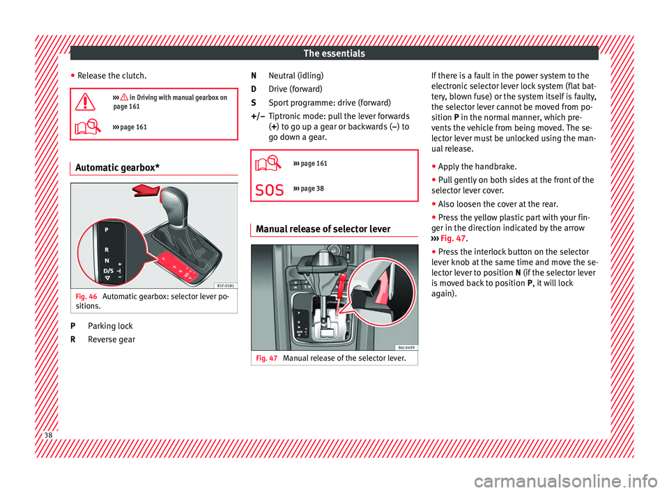
Fig. 46
Automatic gearbox: selector lever po-
s ition
s. Parking lock
R
ev
erse g
ear
P
R Neutral (idling)
Drive (forw
ard)
Sport programme: drive (forward)
Tiptronic mode: pull the lever forwards
(+) to go up a gear or backwards ( –) to
go down a gear.
››› page 161
››› page 38 Manual release of selector lever
Fig. 47
Manual release of the selector lever. N
D
S
+/–
If there is a fault in the power system to the
el
ectr
onic sel
ector lever lock system (flat bat-
tery, blown fuse) or the system itself is faulty,
the selector lever cannot be moved from po-
sition P in the normal manner, which pre-
vents the vehicle from being moved. The se-
lector lever must be unlocked using the man-
ual release.
● Apply the handbrake.
● Pull gently on both sides at the front of the
selector lev
er cover.
● Also loosen the cover at the rear.
● Press the yellow plastic part with your fin-
ger in the direction indicat
ed by the arrow
››› Fig. 47.
● Press the interlock button on the selector
lever knob at
the same time and move the se-
lector lever to position N (if the selector lever
is moved back to position P, it will lock
again). 38
Page 53 of 252
The essentials
Emergency towing of the vehi-
c l
e
T o
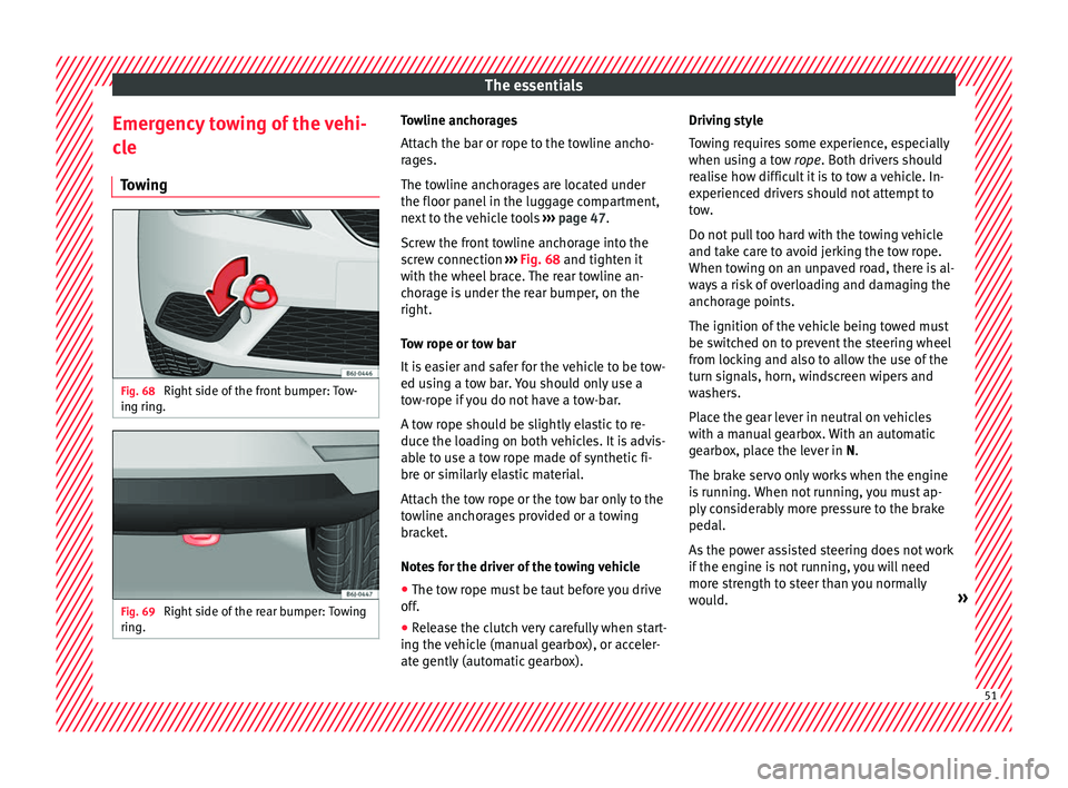
wing Fig. 68
Right side of the front bumper: Tow-
in g rin
g. Fig. 69
Right side of the rear bumper: Towing
rin g. Towline anchorages
Att
ac
h the b ar or r
ope to the towline ancho-
rages.
The towline anchorages are located under
the floor panel in the luggage compartment,
next to the vehicle tools ››› page 47.
Screw the front towline anchorage into the
screw connection ››› Fig. 68 and tighten it
with the wheel brace. The rear towline an-
chorage is under the rear bumper, on the
right.
Tow rope or tow bar
It is easier and safer for the vehicle to be tow-
ed using a tow bar. You should only use a
tow-rope if you do not have a tow-bar.
A tow rope should be slightly elastic to re-
duce the loading on both vehicles. It is advis-
able to use a tow rope made of synthetic fi-
bre or similarly elastic material.
Attach the tow rope or the tow bar only to the
towline anchorages provided or a towing
bracket.
Notes for the driver of the towing vehicle
● The tow rope must be taut before you drive
off.
● Rele
ase the clutch very carefully when start-
ing the vehic
le (manual gearbox), or acceler-
ate gently (automatic gearbox). Driving style
Towin
g requires some experience, especially
when using a tow rope. Both drivers should
realise how difficult it is to tow a vehicle. In-
experienced drivers should not attempt to
tow.
Do not pull too hard with the towing vehicle
and take care to avoid jerking the tow rope.
When towing on an unpaved road, there is al-
ways a risk of overloading and damaging the
anchorage points.
The ignition of the vehicle being towed must
be switched on to prevent the steering wheel
from locking and also to allow the use of the
turn signals, horn, windscreen wipers and
washers.
Place the gear lever in neutral on vehicles
with a manual gearbox. With an automatic
gearbox, place the lever in N.
The brake servo only works when the engine
is running. When not running, you must ap-
ply considerably more pressure to the brake
pedal.
As the power assisted steering does not work
if the engine is not running, you will need
more strength to steer than you normally
would. » 51
Page 54 of 252
The essentials
››› in Notes on page 79
››› page 79 Tow-starting
If the engine will not start, first try starting it
usin
g the b
attery of another vehicle
››› page 52. You should only attempt to tow-
start a vehicle if charging the battery does
not work. This is done by leveraging wheel
movement.
When tow-starting a vehicle with a petrol en-
gine, do not tow it more than a short dis-
tance, otherwise unburned fuel can enter the
catalytic converter.
However, if your vehicle has to be tow-star-
ted:
● Engage 2 nd
or 3 rd
ge ar
.
● Keep the clutch pressed down.
● Switch the ignition on.
● Once both vehicles are moving, release the
clutch.
● As
soon as the engine starts, press the
clutch and mo
ve the gear lever into neutral.
This helps to prevent driving into the towing
vehicle.
››› in Notes on page 79
›››
page 79 How to jump start
Jump l e
a d
s The jump lead must have a sufficient wire
cro
s
s section.
If the engine fails to start because of a dis-
charged battery, the battery can be connec-
ted to the battery of another vehicle to start
the engine.
Jump leads
Jump leads must comply with standard DIN
72553 (see cable manufacturer's instruc-
tions). The wire cross section must be at least
25 mm 2
for petrol engines and at least
35 mm 2
for diesel engines. Note
● The vehic l
es must not touch each other,
otherwise electricity could flow as soon as
the positive terminals are connected.
● The discharged battery must be properly
connected to the on-bo
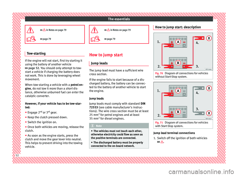
ard network. How to jump start: description
Fig. 70
Diagram of connections for vehicles
w ithout
St
art-Stop system. Fig. 71
Diagram of connections for vehicles
w ith
Star
t-Stop system. Jump lead terminal connections
1. Switch off the ignition of both vehicles
››
› .
52
Page 59 of 252
Safe driving
risk of injury. The following list includes most
of the s
afety
equipment in your SEAT:
● Three-point seat belts
● Belt tension limiter for the front and rear
side seats
● Belt
tensioners for the front seats
● Front airbags
● Side airbags in the front seat backrests,
with ches
t and head protection
● “ISOFIX” anchor points for “ISOFIX” rear
child se
at system
● Height-adjustable front head restraints
● Rear-centre head restraints with in-use po-
sition and non-use pos
ition
● Adjustable steering column
The safety equipment
mentioned above
works together to provide you and your pas-
sengers with the best possible protection in
the event of an accident. However, these
safety systems can only be effective if you
and your passengers are sitting in a correct
position and use this equipment properly.
Safety is everyone's business! Correct position for passengers
Correct s
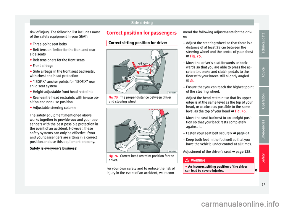
itting position for driver Fig. 75
The proper distance between driver
and s t
eerin g wheel Fig. 76
Correct head restraint position for the
driv er
. For your own safety and to reduce the risk of
injur
y
in the ev ent
of an accident, we recom- mend the following adjustments for the driv-
er:
– Adjust the steering wheel so that there is a
distanc
e of at least 25 cm between the
steering wheel and the centre of your chest
››› Fig. 75.
– Move the driver's seat forwards or back-
wards
so that you are able to press the ac-
celerator, brake and clutch pedals to the
floor with your knees still slightly angled
››› .
– Ensure that you can reach the highest point
of the s
teerin
g wheel.
– Adjust the head restraint so that its upper
edge is at
the same level as the top of your
head, or as close as possible to the same
level as the top of your head ››› Fig. 76.
– Move the seat backrest to an upright posi-
tion so that y
our back rests completely
against it.
– Fasten your seat belt securely ››› p
age 61.
– Keep both feet in the footwell so that you
have the v
ehicle under control at all times.
Adjustment of the driver's seat ››› page 128. WARNING
● An incorrect s
itting position of the driver
can lead to severe injuries. » 57
Technical data
Advice
Operation
Emergencies
Safety
Page 63 of 252
Seat belts
●
Do not swap the c entr
e rear head restraint
with either of the outer seat rear head re-
straints. Risk of injury in case of an accident! Note
Note the instructions on the head restraints
a djus tment
.Pedal area
P ed
al
s –
Ensure that you can always press the accel-
er at
or , br
ake and clutch pedals unimpaired
to the floor.
– Ensure that the pedals can return unim-
paired to their initi
al positions.
– Ensure that the floor mats are securely fas-
tened during the trip and do not o
bstruct
the pedals ››› .
On ly
u se floor m
ats which leave the pedals
clear and which are secured to prevent them
from slipping. You can obtain suitable floor
mats from a specialised dealership.
If a brake circuit fails, the brake pedal must
be pressed down thoroughly in order to stop
the vehicle. Wear suitable footwear
Alway
s wear shoes which support your feet
properly and give you a good feeling for the
pedals. WARNING
● If the peda l
s are obstructed, an accident
may occur. Risk of serious injuries.
● Never lay or fit floor mats or other floor cov-
erings o
ver the original floor mats. This
would reduce the pedal area and could ob-
struct the pedals. Risk of accident.
● Never place objects in the driver footwell.
An object
could move into the pedal area and
impair pedal operation. In the event of a sud-
den driving or braking manoeuvre, you will
not be able to operate the brake, clutch or ac-
celerator pedal. Risk of accident! Seat belts
Wh y
w e
ar a seat belt?
Number of seats Your vehicle has
five seats, tw
o in the front
and three in the rear. Each seat is equipped
with a three-point seat belt.
In some versions, your vehicle is approved
only for four seats. Two front seats and two
rear seats. WARNING
● Never tran s
port more than the permitted
amount of people in your vehicle.
● Every vehicle occupant must properly fas-
ten and wear the se
at belt belonging to his or
her seat. Children must be protected with an
appropriate child restraint system. 61
Technical data
Advice
Operation
Emergencies
Safety
Page 84 of 252
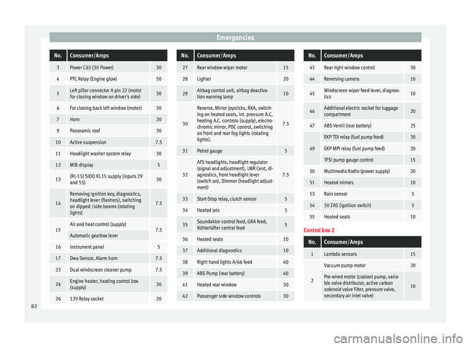
EmergenciesNo.Consumer/Amps
3Power C63 (30 Power)30
4PTC Relay (Engine glow)50
5Left pillar connector A pin 22 (motor
for closing window on driver's side)30
6For closing back left window (motor)30
7Horn20
9Panoramic roof30
10Active suspension7.5
11Headlight washer system relay30
12MIB display5
13(RL-15) SIDO Kl.15 supply (inputs 29
and 55)30
14
Removing ignition key, diagnostics,
headlight lever (flashers), switching
on dipped /side beams (rotating
lights)
7.5
15Air and heat control (supply)7.5Automatic gearbox lever
16Instrument panel5
17Dwa Sensor, Alarm horn7.5
23Dual windscreen cleaner pump7.5
24Engine heater, heating control box
(supply)30
2612V Relay socket20
No.Consumer/Amps
27Rear window wiper motor15
28Lighter20
29Airbag control unit, airbag deactiva-
tion warning lamp10
30
Reverse, Mirror joysticks, RKA, switch-
ing on heated seats, int. pressure A.C,
heating A.C. controls (supply), electro-
chromic mirror, PDC control, switching
on front and rear fog lights (rotating
lights).
7.5
31Petrol gauge5
32
AFS headlights, headlight regulator
(signal and adjustment), LWR Cent, di-
agnostics, front headlight lever
(switch on), Dimmer (headlight adjust-
ment)
7.5
33Start-Stop relay, clutch sensor5
34Heated jets5
35Soundaktor control feed, GRA feed,
Kühlerlüfter central feed5
36Heated seats10
37Additional diagnostics10
38Right hand lights A/66 feed40
39ABS Pump (rear battery)40
41Heated rear window30
42Passenger side window controls30
No.Consumer/Amps
43Rear right window control30
44Reversing camera10
45Windscreen wiper feed lever, diagnos-
tics10
46Additional electric socket for luggage
compartment20
47ABS Ventil (rear battery)25
49
EKP TDI relay (fuel pump feed)30
EKP MPI relay (fuel pump feed)20
TFSI pump gauge control15
50Multimedia Radio (power supply)20
51Heated mirrors10
53Rain sensor5
5430 ZAS (ignition switch)5
55Heated seats10
Control box 2
No.Consumer/Amps
1Lambda sensors15
2
Vacuum pump motor20
Pre-wired motor (coolant pump, varia-
ble valve distributor, active carbon
solenoid valve filter, pressure valve,
secondary air inlet valve)
10
82
Page 153 of 252
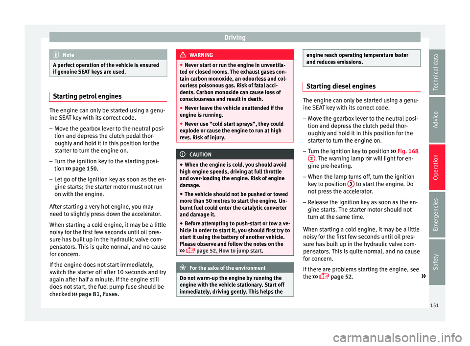
Driving
Note
A perfect operation of the vehicle is ensured
if genuine S
EAT keys are used.Starting petrol engines
The engine can only be started using a genu-
ine SEA
T k
ey with its correct code.
– Move the gearbox lever to the neutral posi-
tion and depress
the clutch pedal thor-
oughly and hold it in this position for the
starter to turn the engine on.
– Turn the ignition key to the starting posi-
tion ›››
p
age 150.
– Let go of the ignition key as soon as the en-
gine starts; the s
tarter motor must not run
on with the engine.
After starting a very hot engine, you may
need to slightly press down the accelerator.
When starting a cold engine, it may be a little
noisy for the first few seconds until oil pres-
sure has built up in the hydraulic valve com-
pensators. This is quite normal, and no cause
for concern.
If the engine does not start immediately,
switch the starter off after 10 seconds and try
again after half a minute. If the engine still
does not start, the fuel pump fuse should be
checked ›››
page 81, Fuses. WARNING
● Never st ar
t or run the engine in unventila-
ted or closed rooms. The exhaust gases con-
tain carbon monoxide, an odourless and col-
ourless poisonous gas. Risk of fatal acci-
dents. Carbon monoxide can cause loss of
consciousness and result in death.
● Never leave the vehicle unattended if the
engine is ru
nning.
● Never use “cold start sprays”, they could
explode or cau
se the engine to run at high
revs. Risk of injury. CAUTION
● When the engine is c
old, you should avoid
high engine speeds, driving at full throttle
and over-loading the engine. Risk of engine
damage.
● The vehicle should not be pushed or towed
more than 50 metre
s to start the engine. Un-
burnt fuel could enter the catalytic converter
and damage it.
● Before attempting to push-start or tow a ve-
hicle in order t
o start it, you should first try to
start it using the battery of another vehicle.
Please observe and follow the notes on the
››› page 52, How to jump start. For the sake of the environment
Do not warm-up the engine by running the
engine with the v
ehicle stationary. Start off
immediately, driving gently. This helps the engine reach operating temperature faster
and reduce
s
emissions. Starting diesel engines
The engine can only be started using a genu-
ine SEA
T k
ey with its correct code.
– Move the gearbox lever to the neutral posi-
tion and depress
the clutch pedal thor-
oughly and hold it in this position for the
starter to turn the engine on.
– Turn the ignition key to position ››› Fig. 168
2 . The warning lamp
wi
ll
light for en-
gine pre-heating.
– When the lamp turns off, turn the ignition
key to po
sition 3 to start the engine. Do
not pr
es
s the accelerator.
– Release the ignition key as soon as the en-
gine starts.
The starter motor should not
turn at the same time.
When starting a cold engine, it may be a little
noisy for the first few seconds until oil pres-
sure has built up in the hydraulic valve com-
pensators. This is quite normal, and no cause
for concern.
If there are problems starting the engine, see
the ›››
page 52. »
151
Technical data
Advice
Operation
Emergencies
Safety