fuel pressure Seat Ibiza ST 2016 Owner's manual
[x] Cancel search | Manufacturer: SEAT, Model Year: 2016, Model line: Ibiza ST, Model: Seat Ibiza ST 2016Pages: 252, PDF Size: 5.56 MB
Page 38 of 252
The essentials
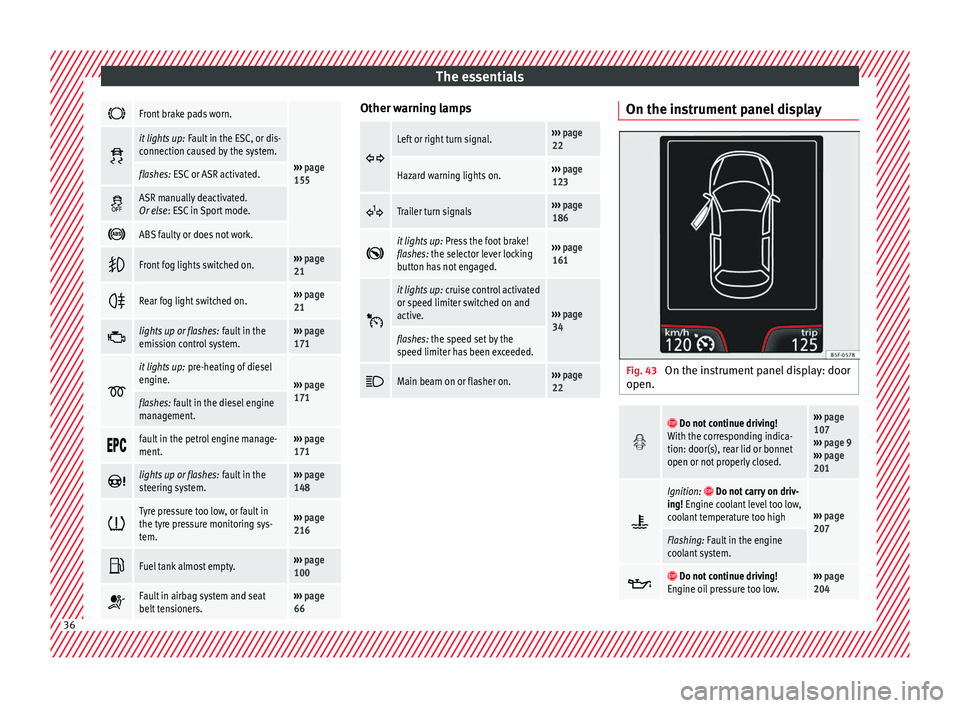
Front brake pads worn.
›››
page
155
it lights up:
Fault in the ESC, or dis-
connection caused by the system.
flashes: ESC or ASR activated.
ASR manually deactivated.
Or else
: ESC in Sport mode.
ABS faulty or does not work.
Front fog lights switched on.›››
page
21
Rear fog light switched on.›››
page
21
lights up or flashes:
fault in the
emission control system.››› page
171
it lights up:
pre-heating of diesel
engine.
››› page
171
flashes: fault in the diesel engine
management.
fault in the petrol engine manage-
ment.›››
page
171
lights up or flashes:
fault in the
steering system.››› page
148
Tyre pressure too low, or fault in
the tyre pressure monitoring sys-
tem.›››
page
216
Fuel tank almost empty.›››
page
100
Fault in airbag system and seat
belt tensioners.›››
page
66 Other warning lamps
Left or right turn signal.›››
page
22
Hazard warning lights on.››› page
123
Trailer turn signals›››
page
186
it lights up:
Press the foot brake!
flashes: the selector lever locking
button has not engaged.››› page
161
it lights up:
cruise control activated
or speed limiter switched on and
active.
››› page
34
flashes: the speed set by the
speed limiter has been exceeded.
Main beam on or flasher on.›››
page
22 On the instrument panel display
Fig. 43
On the instrument panel display: door
open.
Do not continue driving!
With the corresponding indica-
tion: door(s), rear lid or bonnet
open or not properly closed.››› page
107
››› page 9
››› page
201
Ignition: Do not carry on driv-
ing! Engine coolant level too low,
coolant temperature too high
››› page
207
Flashing: Fault in the engine
coolant system.
Do not continue driving!
Engine oil pressure too low.››› page
204 36
Page 78 of 252
Emergencies
●
Never st ar
t the engine when the vehicle is
on the jack. Risk of accident.
● If work is to be carried out underneath the
vehicle, thi
s must be secured by suitable
means. Otherwise, there is a risk of injury. Note
The jack does not generally require any main-
t enanc e. If
required, it should be greased us-
ing universal type grease. Spare wheel (temporary spare
wheel)*
The temporary spare wheel is stored under
the floor p
anel
in the lug g
age compartment
and is attached by a thumbnut.
How to use the temporary spare wheel
If you ever have a punctured tyre or loss of
pressure, the temporary spare wheel is only
intended for temporary use until you reach a
workshop. Change it for a duty wheel as soon
as possible.
Please note the following restrictions when
using the temporary spare wheel. This tem-
porary spare wheel has been specially de-
signed for your vehicle, thus, it cannot be
changed with the temporary spare wheel
from another vehicle. No other type of tyre (normal summer or win-
ter tyre) m
ay be fitted on the compact tempo-
rary spare wheel rim.
Snow chains
For technical reasons, snow chains must not
be used on the temporary spare wheel.
If you have a puncture on one of the front
wheels when using snow chains, fit the tem-
porary spare wheel in place of one of the rear
wheels. Fit the snow chains on the rear wheel
that you have removed and replace the punc-
tured front wheel with this wheel.
Extraction of the spare wheel in vehicles
with SEAT SOUND 6 speakers (with subwoof-
er)*
● Disassemble the subwoofer's floor p
anel
(carpet) as follows:
● Pull the carpet upwards to remove it.
● Disconnect the subwoofer's s
peaker cable.
● Turn the securing wheel anti-clockwise.
● Remove the subwoofer s
peaker and the
spare wheel.
● When replacing the spare wheel, place the
subwoofer s
peaker in the direction indicated
by the arrow and with the word “FRONT” fac-
ing forward.
● Reconnect the speaker cable and firmly ro-
tate the sec urin
g wheel clockwise so that the subwoofer syst
em and wheel
are firmly in
place. WARNING
● After fittin g the t
emporary spare wheel,
check the tyre pressures as soon as possible.
Failure to do so may cause an accident. The
tyre pressures are listed on the inside of the
fuel tank flap.
● Do not drive at over 80 km/h (50 mph)
when the temporary
spare wheel is fitted on
the vehicle: risk of accident!
● Avoid heavy acceleration, hard braking and
fast
cornering: risk of accident!
● Never use more than one temporary spare
wheel at the same time, ri
sk of accident.
● No other type of tyre (normal summer or
winter tyr
e) may be fitted on the compact
temporary spare wheel rim. Tyre repair
TM S (T
y
re Mobility System)* Read the additional information carefully
› ›
›
p
age 46
The Anti-puncture kit* (Tyre Mobility System)
will reliably seal punctures caused by the
penetration of a foreign body of up to about
4 mm in diameter. Do not remove foreign ob-
jects, e.g. screws or nails, from the tyre.
76
Page 84 of 252
EmergenciesNo.Consumer/Amps
3Power C63 (30 Power)30
4PTC Relay (Engine glow)50
5Left pillar connector A pin 22 (motor
for closing window on driver's side)30
6For closing back left window (motor)30
7Horn20
9Panoramic roof30
10Active suspension7.5
11Headlight washer system relay30
12MIB display5
13(RL-15) SIDO Kl.15 supply (inputs 29
and 55)30
14
Removing ignition key, diagnostics,
headlight lever (flashers), switching
on dipped /side beams (rotating
lights)
7.5
15Air and heat control (supply)7.5Automatic gearbox lever
16Instrument panel5
17Dwa Sensor, Alarm horn7.5
23Dual windscreen cleaner pump7.5
24Engine heater, heating control box
(supply)30
2612V Relay socket20
No.Consumer/Amps
27Rear window wiper motor15
28Lighter20
29Airbag control unit, airbag deactiva-
tion warning lamp10
30
Reverse, Mirror joysticks, RKA, switch-
ing on heated seats, int. pressure A.C,
heating A.C. controls (supply), electro-
chromic mirror, PDC control, switching
on front and rear fog lights (rotating
lights).
7.5
31Petrol gauge5
32
AFS headlights, headlight regulator
(signal and adjustment), LWR Cent, di-
agnostics, front headlight lever
(switch on), Dimmer (headlight adjust-
ment)
7.5
33Start-Stop relay, clutch sensor5
34Heated jets5
35Soundaktor control feed, GRA feed,
Kühlerlüfter central feed5
36Heated seats10
37Additional diagnostics10
38Right hand lights A/66 feed40
39ABS Pump (rear battery)40
41Heated rear window30
42Passenger side window controls30
No.Consumer/Amps
43Rear right window control30
44Reversing camera10
45Windscreen wiper feed lever, diagnos-
tics10
46Additional electric socket for luggage
compartment20
47ABS Ventil (rear battery)25
49
EKP TDI relay (fuel pump feed)30
EKP MPI relay (fuel pump feed)20
TFSI pump gauge control15
50Multimedia Radio (power supply)20
51Heated mirrors10
53Rain sensor5
5430 ZAS (ignition switch)5
55Heated seats10
Control box 2
No.Consumer/Amps
1Lambda sensors15
2
Vacuum pump motor20
Pre-wired motor (coolant pump, varia-
ble valve distributor, active carbon
solenoid valve filter, pressure valve,
secondary air inlet valve)
10
82
Page 85 of 252
Fuses and bulbs
Fuse arrangement in engine compart-
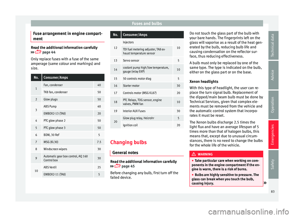
ment Read the additional information carefully
›››
p
age 44
Only replace fuses with a fuse of the same
amperage (same colour and markings) and
size.
No.Consumer/Amps
1Fan, condenser40
TK8 fan, condenser50
2Glow plugs50
3ABS Pump40
EMBOX2-13 (TA8)20
4PTC glow phase 250
5PTC glow phase 350
6BDM, 30 ReF5
7MSG (KL30)7.5
8Windscreen wipers30
9Automatic gear box control, AQ 160
Control box30
10ABS Ventil25
EMBOX2-11 (TA8)5
No.Consumer/Amps
12
Injectors
10TDI fuel metering adjuster, TA8 ex-
haust temperature sensor
13Servo sensor5
14coolant pump high/low temperature,
gauge (relay EKP)10
1550 controls motor diag5
16Starter motor30
17Controls motor (MSG KL87)20
18PTC Relays, TOG sensor, engine
valves, PWM fan10
19Interior AUX Fuses30
20Glow plug relay, Heizrohr5
Ignition coil20 Changing bulbs
Gener al
not
es Read the additional information carefully
› ›
›
p
age 45
Before changing any bulb, first turn off the
failed device. Do not touch the glass part of the bulb with
your bare h
ands. The fingerprints left on the
glass will vaporise as a result of the heat gen-
erated by the bulb, reducing bulb life and
causing condensation on the reflector sur-
face, thus reducing effectiveness.
A bulb must only be replaced by one of the
same type. The type is indicated on the bulb,
either on the glass part or on the base.
Xenon headlights
With this type of headlight, the user can re-
place the turn signal bulb. Replacement of
the dipped/main beam bulb must be done by
Technical Services, given that complex ele-
ments must be removed from the vehicle and
the automatic control system that incorpo-
rates it must be reset.
The Xenon bulbs discharge 2.5 times the
light flux and have an average lifespan of 5
times more than that of halogen bulbs, this
means that, except due to unusual circum-
stances, there is no need to change the bulbs
for the whole life of the vehicle. WARNING
● Take p ar
ticular care when working on com-
ponents in the engine compartment if the en-
gine is warm, there is a risk of burns.
● Bulbs are highly sensitive to pressure. The
glass
can break when you touch the bulb,
causing injury. » 83
Technical data
Advice
Operation
Emergencies
Safety
Page 102 of 252
Operation
●
Additiona l
lights and other accessories in
front of the air inlet reduce the cooling effect
of the coolant. At high outside temperatures
and high engine loads, there is a risk of the
engine overheating.
● The front spoiler also ensures proper distri-
bution of the coo
ling air when the vehicle is
moving. If the spoiler is damaged this can re-
duce the cooling effect, which could cause
the engine to overheat. Seek specialist assis-
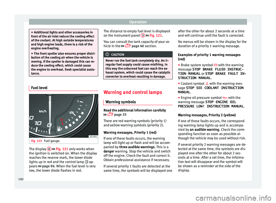
tance. Fuel level
Fig. 123
Fuel gauge. The display
6
› ›
› Fig. 121 on
ly works when
the ignition is switched on. When the display
reaches the reserve mark, the lower diode
lights up in red and the control lamp ap-
pears ››› page 96. When the fuel level is very
low, the lower diode flashes in red. The distance to empty fuel level is displayed
on the instrument p
anel 3
› ››
Fig. 121
.
Y ou c
an consult the tank capacity of your ve-
hicle in the ›››
page 40 section. CAUTION
Never run the fuel tank completely dry. An ir-
regu l
ar fuel supply could cause misfiring. In
this way the unburned fuel can reach the ex-
haust system, which could cause the catalytic
converter to overheat resulting in damage. Warning and control lamps
W arnin
g symbo l
s Read the additional information carefully
› ›
›
p
age 35
There are red warning symbols (priority 1)
and yellow warning symbols (priority 2).
Warning messages, Priority 1 (red)
If one of these faults occurs, the warning
lamp will light up or flash and will be accom-
panied by three audible warnings. This is a
danger warning. Stop the vehicle and switch
off the engine. Check the fault and correct it.
Obtain professional assistance if necessary.
If several priority 1 faults are detected at the
same time, the symbols will be displayed one after the other for about 2 seconds at a time
and will
continue until the fault is corrected.
No menus will be shown in the display for the
duration of a priority 1 warning message.
Examples of priority 1 warning messages
(red)
● Brake system symbol with the warning
me
ssage STOP BRAKE FLUID INSTRUC-
TION MANUAL or STOP BRAKE FAULT IN-
STRUCTION MANUAL .
● Coolant symbol with the warning me
s-
sage STOP SEE COOLANT INSTRUCTION
MANUAL .
● Engine oil pressure symbol with the
warning me
ssage STOP ENGINE OIL
PRESSURE LOW! INSTRUCTION MANUAL .
Warning messages, Priority 2 (yellow)
If one of these faults occurs, the correspond-
ing warning lamp lights up and is accompa-
nied by an audible warning. Check the corre-
sponding function as soon as possible al-
though the vehicle may be used without risk.
If several priority 2 warning messages are de-
tected at the same time, the symbols are dis-
played one after the other for about 2 sec-
onds at a time. After a set time, the informa-
tion text will disappear and the symbol will
be shown as a reminder at the side of the
display.
100
Page 138 of 252
Operation
Note
● The tyre pr e
ssure must be adjusted accord-
ing to the load. When necessary check the
tyre pressures on the label located on the in-
side fuel tank flap ››› page 213.
● Air circulation in the vehicle helps reduce
fogging of
the windows. Used air escapes
through ventilation slits in the side trim of
the luggage compartment. Ensure that the
ventilation slots are never covered.
● Straps for securing the load to the fasten-
ing rings* ar
e commercially available from ac-
cessory shops. Fastening rings*
3 Applies to the model: IBIZA ST
Fig. 157
Location of fastening rings in lug-
g ag
e c omp
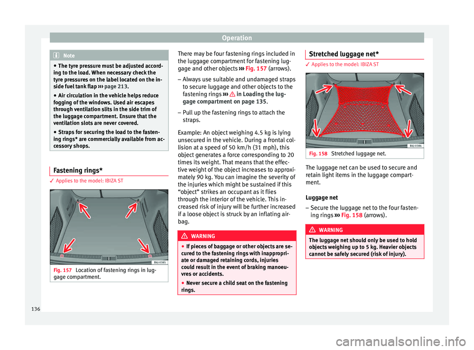
artment. There may be four fastening rings included in
the lug
g
ag e c
ompartment for fastening lug-
gage and other objects ››› Fig. 157 (arrows).
– Always use suitable and undamaged straps
to secure lug
gage and other objects to the
fastening rings ››› in Loading the lug-
g ag
e c omp
artment on page 135.
– Pull up the fastening rings to attach the
straps.
Ex
ample: An object weighing 4.5 kg is lying
unsecured in the vehicle. During a frontal col-
lision at a speed of 50 km/h (31 mph), this
object generates a force corresponding to 20
times its weight. That means that the effec-
tive weight of the object increases to approxi-
mately 90 kg. You can imagine the severity of
the injuries which might be sustained if this
“object” strikes an occupant as it flies
through the interior of the vehicle. This in-
creased risk of injury will be further increased
if a loose object is struck by an inflating air-
bag. WARNING
● If piece s
of baggage or other objects are se-
cured to the fastening rings with inappropri-
ate or damaged retaining cords, injuries
could result in the event of braking manoeu-
vres or accidents.
● Never secure a child seat on the fastening
rings. Stretched luggage net*
3 Applies to the model: IBIZA ST
Fig. 158
Stretched luggage net. The luggage net can be used to secure and
r
et
ain light it
ems in the luggage compart-
ment.
Luggage net
– Secure the luggage net to the four fasten-
ing rings
››› Fig. 158 (arrows). WARNING
The luggage net should only be used to hold
obj ect
s weighing up to 5 kg. Heavier objects
cannot be safely secured (risk of injury). 136
Page 150 of 252
Operation
It is possible, however, to set the blower
s peed t
o suit
requirements.
● Turn control 10
› ››
Fig. 167
cou
nter-clock-
wise (to lower the speed) or clockwise (to in-
crease the speed).
Climatronic will switch off when the blower
switches off. WARNING
Read and observe the safety warnings ››› in
General not
es on page 140. Windscreen defrost
Switching on windscreen defrosting
●
Press the button
12
› ›
›
Fig. 167
.
Switching off windscreen defrosting
● Press button
12
› ›
›
Fig. 167
several
times or press the AUTO button.
The t emper
atur
e is regulated automatically.
The air output is increased from vents 1 and
2 ›››
page 141. Driving
Ad dr
es
s
Introduction The power steering is not hydraulic but elec-
tromech
anic
al. The advantage of this steer-
ing is that it foes not need flexible hydraulic
pipes, hydraulic oil, pump, filter or other
parts. The electromechanical system saves
fuel. Whereas a hydraulic system needs con-
tinuous oil pressure, electromechanical
steering only needs power when it is used.
In vehicles with electromechanical steering,
the assisted steering function automatically
adjusts according to vehicle speed, steering
wheel torque and wheel orientation. The
power steering only works when the engine
is running. WARNING
If the power steering does not work, you will
need much more s tr
ength to turn the wheel.
This has a considerable effect on vehicle
safety.
● The power steering only works when the
engine is ru
nning.
● Never allow the vehicle to move when the
engine is sw
itched off.
● Never remove the key from the ignition
while the v
ehicle is moving. The steering lock could be engaged and vehicle steering would
not work.
Note
The ignition of the vehicle being towed must
be sw itched on t
o prevent the steering wheel
from locking and also to allow the use of the
turn signals, horn, windscreen wipers and
washers. Control lamp
The control lamp should light up for a few
sec
ond
s when the ignition i
s switched on. It
should go out once the engine is started.
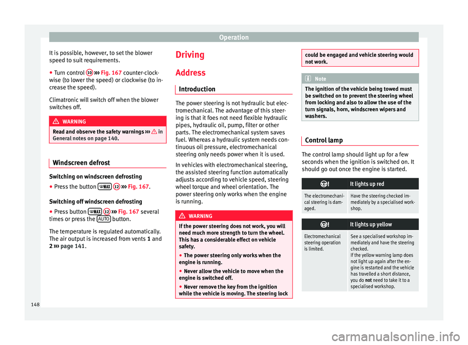
It lights up red
The electromechani-
cal steering is dam-
aged.Have the steering checked im-
mediately by a specialised work-
shop.
It lights up yellow
Electromechanical
steering operation
is limited.See a specialised workshop im-
mediately and have the steering
checked.
If the yellow warning lamp does
not light up again after the en-
gine is restarted and the vehicle
has travelled a short distance,
you do not need to take it to a
specialised workshop. 148
Page 163 of 252
Driving
Manual gearbox Driv in
g w ith m
anual gearboxRead the additional information carefully
›››
p
age 37
Certain versions of the model may include a
6-speed manual gearbox, and its diagram is
shown on the gearbox lever.
The reverse gear can only be engaged when
the car is stationary. When the engine is run-
ning and before engaging this gear, wait
about 6 seconds with the clutch pressed
down thoroughly in order to protect the gear-
box.
The reverse lights switch on when the reverse
gear is selected and the ignition is on. WARNING
● When the engine is ru
nning, the vehicle
will start to move as soon as a gear is engag-
ed and the clutch released.
● Never select the reverse gear when the ve-
hicle is
in motion. Risk of accident. Note
● Do not re s
t your hand on the gear lever
while driving. The pressure of your hand
could cause premature wear on the selector
forks in the gearbox. ●
When chan gin
g gear, you should always
depress the clutch fully to avoid unnecessary
wear and damage.
● Do not “slip” the clutch to hold the vehicle
on a hill.
This causes premature wear and
damage to the clutch.
● Do not leave your foot on the clutch pedal;
although the pres
sure may seem insignifi-
cant, it can cause the premature wear of the
clutch plate. Use the foot rest when you do
not need to change gear. Gear-change indicator
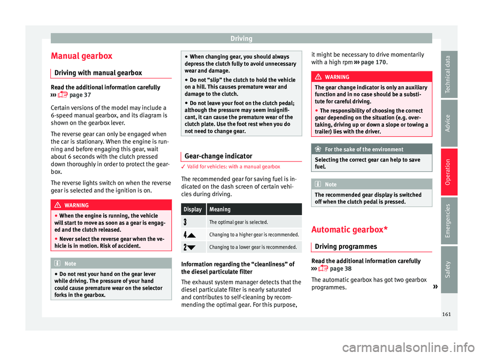
3 Valid for vehicles: with a manual gearbox
The r ec
ommended gear for saving fuel is in-
dicated on the dash screen of certain vehi-
cles during driving.
DisplayMeaning
The optimal gear is selected.
Changing to a higher gear is recommended.
Changing to a lower gear is recommended.
Information regarding the “cleanliness” of
the die
sel
par
ticulate filter
The exhaust system manager detects that the
diesel particulate filter is nearly saturated
and contributes to self-cleaning by recom-
mending the optimal gear. For this purpose, it might be necessary to drive momentarily
with a high rpm
›››
page 170. WARNING
The gear change indicator is only an auxiliary
function and in no c a
se should be a substi-
tute for careful driving.
● The responsibility of choosing the correct
gear depending on the s
ituation (e.g. over-
taking, driving up or down a slope or towing a
trailer) lies with the driver. For the sake of the environment
Selecting the correct gear can help to save
fuel. Note
The recommended gear display is switched
off when the clut c
h pedal is pressed. Automatic gearbox*
Driv ing pr
ogr
ammes Read the additional information carefully
› ›
›
p
age 38
The automatic gearbox has got two gearbox
programmes. »
161
Technical data
Advice
Operation
Emergencies
Safety
Page 171 of 252
Driving
Avoid short journeys
T o r
educ e the c
onsumption and emission of
polluting exhaust gases, the engine and the
exhaust gas filtration systems should reach
the optimum operating temperature.
With the engine cold, fuel consumption is
proportionally higher. The engine does not
warm up and fuel consumption does not nor-
malise until having driven approximately four
kilometres (2.5 miles). This is why we recom-
mend avoiding short trips whenever possi-
ble.
Maintain the correct tyre pressures
Bear in mind that keeping the tyres at an ad-
equate pressure saves fuel. If the tyre pres-
sure is just one bar (14.5 psi/100 kPa) too
low, fuel consumption can increase by as
much as 5%. Due to the greater rolling resist-
ance, under-inflation also increases tyre wear
wear and impairs handling.
The tyre pressures should always be checked
when the tyres are cold.
Do not use winter tyres all year round as they
increase fuel consumption by up to 10%.
Avoid unnecessary weight
Given that every kilo of extra weight will in-
crease the fuel consumption, it is advisable
to always check the luggage compartment to
make sure that no unnecessary loads are be-
ing transported. A roof rack is often left in place for the sake
of conv
enience, even when it is no longer
needed. At a speed of 100 km/h (62 mph)
and 120 km/h (75 mph) your vehicle will use
about 12% more fuel as a result of the extra
wind resistance caused by the roof rack even
when it is not in use.
Save electricity
The engine activates the alternator, which
produces electricity. With the need for elec-
tricity, fuel consumption also increases. Be-
cause of this, always turn off electrical devi-
ces when you do not need them. Examples of
devices that use a lot of electricity are: the
blower at high speeds, the rear window heat-
ing or the seat heaters*. Note
● If y our
vehicle has Start-Stop, it is not rec-
ommended that you switch this function off.
● It is recommended that you close the win-
do
ws when driving at more than 60 km/h
(37 mph)
● Do not drive with your foot resting on the
clutch pe
dal, as the pressure can make the
plate spin, more fuel will be used and it can
burn the clutch plate lining, causing a serious
fault.
● Do not hold the car on a hill with the clutch,
use the foot br
ake or hand brake, using the
latter to start. The fuel consumption will be lower and you will prevent the clutch plate
from being d
am
aged.
● On descents, use the engine brake, chang-
ing to the ge
ar that is more suitable for the
slope. Fuel consumption will be “zero” and
the brakes will not suffer. Engine management and ex-
haus
t
gas purification system
Introduction WARNING
● Becau se of
the high temperatures which
can occur in the exhaust purification system
(catalytic converter or diesel particulate fil-
ter), do not park the vehicle where the ex-
haust can come into contact with flammable
materials under the car (e.g. on grass or at
the forest edge). Fire hazard!
● Do not apply wax underneath the vehicle
around the are
a of the exhaust system: Fire
hazard! Note
While the control lamps , , or re-
main lit, ther e m
ay be engine problems, fuel
consumption may increase and the engine
may lose power. 169
Technical data
Advice
Operation
Emergencies
Safety
Page 189 of 252
Towing bracket device and trailer
Tyre pressure
Set ty
re pr
essure to the maximum permissi-
ble pressure shown on the sticker on the in-
side of the fuel tank flap. Set the tyre pres-
sure of the trailer tyres in accordance with the
trailer manufacturer's recommendations.
Exterior mirrors
Check whether you can see enough of the
road behind the trailer with the standard rear
vision mirrors. If this is not the case, you
should have additional exterior mirrors fitted.
Both exterior mirrors should be mounted on
hinged extension brackets. Adjust the mirrors
to give sufficient vision to the rear. WARNING
Never transport people in a trailer. This could
res u
lt in fatal accidents. Note
● Tow in
g a trailer places additional demands
on the vehicle. We recommend additional
services between the normal inspection inter-
vals if the vehicle is used frequently for tow-
ing a trailer.
● Find out whether special regulations apply
to tow
ing a trailer in your country. Ball coupling of towing bracket*
The ball coupling is provided with instruc-
tions on fittin
g and r
emoving the ball cou-
pling of the towing bracket. WARNING
The towing bracket ball coupling must be
stor ed sec
urely in the luggage compartment
to prevent them being flung through the vehi-
cle and causing injury. Note
● By l a
w, the ball coupling must be removed
if a trailer is not being towed if it obscures
the number plate. Driving tips
Driving with a trailer always requires extra
c
ar
e.
W eight
distribution
The weight distribution of a loaded trailer
with an unladen vehicle is very unfavourable.
However, if this cannot be avoided, drive ex-
tra slowly to allow for the unbalanced weight
distribution. Speed
The stabi
lity of the vehicle and trailer is re-
duced with increasing speed. For this reason,
it is advisable not to drive at the maximum
permissible speed in an unfavourable road,
weather or wind conditions. This applies es-
pecially when driving downhill.
You should always reduce speed immediately
if the trailer shows the slightest sign of snak-
ing. Never try to stop the “snaking” by in-
creasing speed.
Always brake in due course. If the trailer has
an overrun brake, apply the brakes gently at
first and then, firmly. This will prevent the
jerking that can be caused by locking of trail-
er wheels. Select a low gear in due course
before going down a steep downhill. This en-
ables you to use the engine braking to slow
down the vehicle.
Reheating
At very high temperatures and during pro-
longed slopes, driving with a low gear and
high engine speed; always monitor whether
the excessive coolant temperature gauge is
activated ››› page 207.
187
Technical data
Advice
Operation
Emergencies
Safety