ESP Seat Leon 5D 2008 Owner's Guide
[x] Cancel search | Manufacturer: SEAT, Model Year: 2008, Model line: Leon 5D, Model: Seat Leon 5D 2008Pages: 293, PDF Size: 8.67 MB
Page 115 of 293

Lights and visibility
114A fault in the system is indicated via the flashing of the control lamp
on the
instrument panel. At the same time, a text message with information or
instructions to perform necessary oper ations may appear on the instrument
panel display. Take the vehicle to a qualified workshop and have the fault
repaired.
If the control lamp
lights up on the instrument panel but all the lamps are
operating correctly ⇒page 244, there may still be a fault in the dynamic
curve lighting system (AFS). Take the vehicle to a qualified workshop and
have the fault repaired.
WARNING
If the “automatic dipped light control” is switched on, the dipped head-
lights will not be switched on in fog. They should be switched on manually
using the light switch. The driver is personally responsible for the correct
use of lights in all situations. “Autom atic headlight control” is merely a
system to support the driver. Where necessary, switch on the lights manu-
ally using the light switch.Turning light* When the indicator is switched on to turn or on very tight bends, the right or
left fog lamp automatically comes on to function as a turning light. The
turning light only operates if the dipped lights are on.
WARNING
If the “automatic dipped light control” is switched on, the dipped head-
lights will not be switched on in fog. They should be switched on manually
using the light switch. The driver is personally responsible for the correct
use of lights in all situations. “Automatic headlight control” is merely a
system to support the dr iver. Where necessary, switch on the lights manu-
ally using the light switch.Hazard warning lights
The hazard warning lights are used to draw the attention of
other road users to your vehicle in emergencies.
If your vehicle breaks down:
1. Park your vehicle at a safe distance from moving traffic.
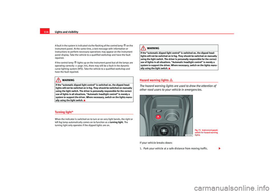
Fig. 75 Instrument panel:
switch for hazard warning
lights
leon_ingles Seite 114 Montag, 26. Januar 2009 4:29 16
Page 117 of 293

Lights and visibility
116Indicator and main beam headlight lever
The turn signal and main beam lever also operates the
parking lights and the headlight flasher.The turn signal and main beam headlight lever has the following
functions:
Switching on the turn signals
– Move the lever all the way up ⇒page 116, fig. 76 to indicate
right , and all the way down to indicate left.
Signalling a lane change
– Push the lever up or down to the point where you incur resistance and then release it. The turn signal will flash several
times. The corresponding warning lamp will also flash. Switching main beam on and off
– Turn the light switch to position
.
–Press the lever forward ⇒ page 116, fig. 76 to switch on the
main beams.
– Pull the lever back towards you to switch the main beam head- lights off again.
Headlight flashers
– Pull the lever towards the steering wheel to operate the flasher.
Switching on parking lights
– Switch the ignition off and remove the key from the lock.
– Move the lever up or down to turn the right or left-hand parking lights on, respectively.
WARNING
The main beam can dazzle other driver s. Risk of accident! Never use the
main beam headlights or the headligh t flasher if they could dazzle other
drivers.
Note
•
The turn signals only work when the ignition is switched on. The corre-
sponding warning lamp
or flashes in the instrume nt panel. The warning
lamp
flashes when the turn signals are operated, provided a trailer is
correctly attached and connected to the vehicle. If a turn signal bulb is defec-
tive, the warning lamp flashes at double speed. If the trailer turn signal bulbs
are damaged, warning lamp
does not light up. Change the bulb.
Fig. 76 Indicator and
main beam lever
A1
A2
A1
A2
A3
A4
leon_ingles Seite 116 Montag, 26. Januar 2009 4:29 16
Page 118 of 293

Lights and visibility117
Safety First
Operating instructions
Practical tips
Te c h n i c a l D a t a
•
The main beam headlights can only be switched on if the dipped beam
headlights are already on. The warning lamp
then comes on in the combi-
instrument.
•
The headlight flasher comes on for as long as you pull the lever – even if
no other lights are switched on. The warning lamp
then comes on in the
combi-instrument.
•
When the parking lights are switched on, the headlight and the rear light
on the corresponding side of the vehicle light up. The parking lights will only
work if the key is removed from the ignition. If the lights are switched on, a
buzzer gives an audible warning while the driver door is open.
•
If the turn signal lever is left on after the key has been taken out of the
ignition lock, an acoustic signal sounds when the driver door is opened. This
is a reminder to switch off the turn signal, unless of course you wish to leave
the parking light on.
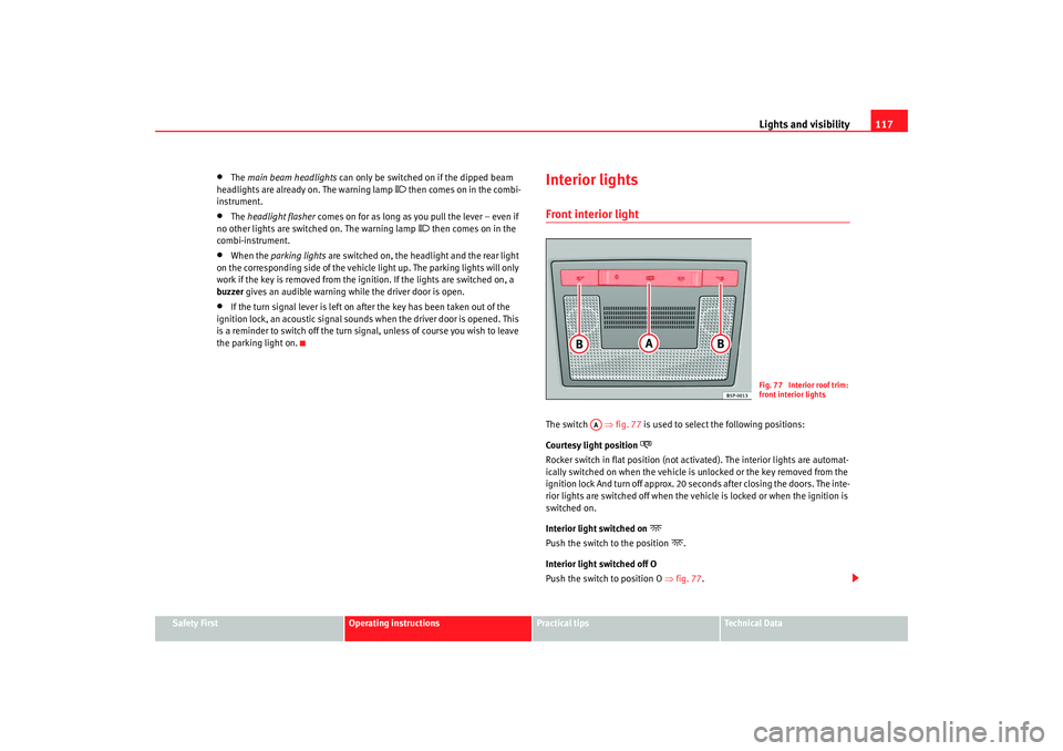
Interior lightsFront interior light The switch ⇒fig. 77 is used to select the following positions:
Courtesy light position
Rocker switch in flat position (not ac tivated). The interior lights are automat-
ically switched on when the vehicle is unlocked or the key removed from the
ignition lock And turn off approx. 20 seconds after closing the doors. The inte-
rior lights are switched off when the vehi cle is locked or when the ignition is
switched on.
Interior light switched on
Push the switch to the position
.
Interior light switched off O
Push the switch to position O ⇒fig. 77 .
Fig. 77 Interior roof trim:
front interior lights
AA
leon_ingles Seite 117 Montag, 26. Januar 2009 4:29 16
Page 121 of 293

Lights and visibility
120
Switching off the wipers
– Move the lever to position .
Intermittent wipe
– Move the lever up to position .
– Move the control to the left or right to set the length of the intervals. Control to the left: long intervals; control to the right:
short intervals. Four wiper interval stages can be set using switch .
Slow wipe
– Move the lever up to position .
Continuous wipe
– Move the lever up to position .
Brief wipe
– Move the lever down to position to give the windscreen a brief
wipe. The wiper will start to move faster if you keep the lever
pressed down for longer than 2 seconds.
Wash and wipe automatic system
– Pull the lever towards the steering wheel - Position . The wash function will start immediately and the wipers will start with a
slight delay. The wash and wiper systems will function at the
same time at speeds of over 120 km/h.
– Release the lever. The wipers will keep running for approximately four seconds.
Optional heated windscreen in the wiper blade* area (page
In some countries and with some versions, there is the possibility of heating
the windscreen in the area of the windscreen wiper blades in order to aid de-
icing in the zone. The function is switched on by pressing the rear heating
window key
.
WARNING
•
Worn and dirty wiper blades obstruct visibility and reduce safety levels.
•
In cold conditions, you should not use the wash / wipe system unless
you have warmed the windscreen with the heating and ventilation system.
The washer fluid could otherwise fr eeze on the windscreen and obscure
your view of the road.
•
Always note the corresponding warnings on ⇒page 215.Caution
In icy conditions, always check that the wiper blades are not frozen to the
glass before using the wipers for the fir st time. If you switch on the wipers
when the wiper blades are frozen to the windscreen, you could damage both
the wiper blades and the wiper motor.
Note
•
The windscreen wipers will only work when the ignition is switched on.
•
In certain versions of vehicles with alarms, the windscreen wiper will only
work when the ignition is on and the bonnet closed.
•
When in use, the wipers do not go as far as the rest position. When the
lever is moved to the 0 position, they move to the rest position.
•
The next speed down will automatically be selected if wiper speed
⇒ page 119, fig. 81 or is selected when the vehicle stops. The set speed
will be resumed when the vehicle starts again
•
The windscreen will be wiped again after approximately five seconds once
the “automatic wipe/wash system” has been operated, provided the vehicle
A0A1
AA
AA
A2A3A4
A5
A2
A3
leon_ingles Seite 120 Montag, 26. Januar 2009 4:29 16
Page 124 of 293

Lights and visibility123
Safety First
Operating instructions
Practical tips
Te c h n i c a l D a t a
Switching on the windscreen wiper and washer system
– Press the lever fully forwards to position ⇒fig. 84 . The wash
function will start immediately and the wiper will start with a
slight delay. The windscreen wash system will function as long as
you hold the lever in this position.
– Release the lever. The wiper then wipes for approximately 4 seconds, and then in intervals again.
– Release the lever. The washer system stops and the wipers func- tion.
WARNING
•
A worn or dirty wiper blade will obst ruct visibility and reduce safety.
•
Always note the corresponding warnings on ⇒page 215, “Changing
the front windscreen wiper blades”.Caution
In icy conditions, always check that the wiper blade is not frozen to the glass
before using the wiper for the first time. If you switch on the wiper when the
wiper blade is frozen to the glass, this could damage both the wiper blade
and the wiper motor.
Note
•
The windscreen wiper will only function when the ignition is switched on
and the tailgate is closed.
•
In reverse gear, with the windscreen wipers switched on, the rear wind-
screen wiper will make one wipe.
Headlight washer system*
The headlight washers clean the headlight lenses.The headlight washers are activated automatically when the windscreen
washer is used and the windscreen wiper lever is pulled towards the steering
wheel for at least 1.5 seconds – provided the dipped headlights or main
beams are switched on. Clean off stubborn dirt (insects, etc.) from the head-
lights at regular intervals, for instance when filling the fuel tank.
Note
•
To ensure that the headlight washers work properly in winter, keep the
nozzle holders in the bumper free of snow and remove any ice with a de-icer
spray.
•
To remove water, the windscreen wipers will be activated from time to
time, the headlight wipers will be activated every three cycles.
MirrorsInterior mirror
It is dangerous to drive if you cannot see clearly through the
rear window.Manual anti-dazzle function for interior mirror
In the basic mirror position, the lever at the bottom edge of the mirror should
be at the front. Pull the lever to the back to select the anti-dazzle function.
A7
leon_ingles Seite 123 Montag, 26. Januar 2009 4:29 16
Page 128 of 293

Seats and stowage127
Safety First
Operating instructions
Practical tips
Te c h n i c a l D a t a
Seats and stowageThe importance of correct seat adjustmentProper seat adjustment optimi ses the level of protection
offered by seat belts and airbags.Your vehicle has five passenger places, two individual front seats and three
places on the rear seat. Each seat is equipped with a three-point seat belt.
The driver seat and the front passenger seat can be adjusted in many ways to
suit the physical requirements of the vehicle occupants. The correct seat
position is very important for:•
a fast and easy operation of all controls on the instrument panel,
•
a relaxed posture which does not cause drowsiness,
•
a safe driving ⇒page 7,
•
ensuring that the seat belts and airbag system provide maximum protec-
tion ⇒page 19.
WARNING
•
If the driver and passengers assume improper sitting positions, they
may sustain critical injuries.
•
More people than available seats must never be transported in your
vehicle.
•
Every passenger in the vehicle must properly fasten and wear the seat
belt belonging to his or her seat. Children must be protected with an appro-
priate child restraint system ⇒page 45, “Child safety”.
•
The front seats and all head restraints must always be adjusted to body
size and the seat belt must always be properly adjusted to provide you and
your passengers with optimum protection.
•
Always keep your feet on the foot well when the vehicle is moving;
never rest them on the dash panel, out of the window or on the seat. This
is also applied to passengers. An inco rrect sitting position exposes you to
an increased risk of injury in case of a sudden braking or an accident. If the
airbag is triggered, you could sustain severe injuries due to an incorrect
sitting position.
•
It is important for the driver and front passenger to keep a distance of
at least 25 cm from the steering wheel or dash panel. Failure to respect the
minimum distance means that the airbag will not protect you. Risk of fatal
injury. The distance between the driver and the steering wheel or between
the front passenger and the dash panel should always be as great as
possible.
•
Adjust the driver or front passenger seat only when the vehicle is
stationary. Otherwise, your seat could move unexpectedly while the
vehicle is moving. This could increase the risk of an accident and therefore,
injury. In addition, while adjusting your seat, you will assume an incorrect
sitting position. Risk of fatal accidents.
•
Special guidelines apply to installing a child seat on the front
passenger seat. When installing a child seat, observe the warning note in
the ⇒page 45, “Child safety”.WARNING (continued)
leon_ingles Seite 127 Montag, 26. Januar 2009 4:29 16
Page 136 of 293

Seats and stowage135
Safety First
Operating instructions
Practical tips
Te c h n i c a l D a t a
sudden braking manoeuvre, you will not be able to use the brake, clutch or
accelerator. Risk of accident.
•
Clothing hung on the coat hooks must not restrict the driver's view.
Risk of accident. The coat hooks are intended only for use with light arti-
cles of clothing. Do not leave any ha rd, sharp or heavy objects in hanging
articles of clothing. During sudden braking manoeuvres or accidents, espe-
cially those involving airbag deployment, these objects could injure the
vehicle occupants.
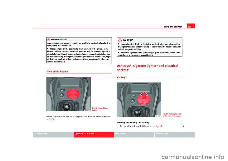
Front drinks holdersOn the centre console, in front of the gear lever, there are two drink holders
⇒ fig. 98 .
WARNING
•
Never place hot drinks in the bottle holder. During normal or sudden
driving manoeuvres, sudden braking or an accident, the hot drink could be
spilled. Danger of scalding.
•
Never use rigid materials (for example, glass or ceramic), these could
cause injury in the case of an accident.
Ashtrays*, cigarette lighter* and electrical
sockets*Ashtray* Opening and closing the ashtray
– To open the ashtray, lift the cover ⇒fig. 99 .
WARNING (continued)
Fig. 98 Front drinks
holder
Fig. 99 Ashtray located
in the front drink holder
leon_ingles Seite 135 Montag, 26. Januar 2009 4:29 16
Page 140 of 293

Seats and stowage139
Safety First
Operating instructions
Practical tips
Te c h n i c a l D a t a
The fire extinguisher* is attached to the luggage compartment carpet by
velcro.
Note
•
The first-aid kit and the fire extinguisher are
not part of the vehicle's
standard equipment.
•
The first aid kit must comply with legal requirements.
•
Observe the expiry date of the contents of the first aid kit. You should
purchase a new first-aid kit as soon as possible after the shelf-life date of the
first-aid kit has expired.
•
The fire extinguisher must comply with legal requirements.
•
Ensure that the fire extinguisher is fu lly functional. The fire extinguisher
should, therefore, be checked regularly. The sticker on the fire extinguisher
will inform you of the next date for checking.
•
Before acquiring accessories and emergency equipment see the instruc-
tions on ⇒page 200.
BootStowing luggage
All luggage must be securely stowed.Please observe the following points to ensure the vehicle handles
well at all times:
– Distribute the load as evenly as possible.
– Place heavy objects as far forward in the luggage compartment
as possible. – Secure luggage in the luggage compartment with suitable straps
on the fastening rings.
WARNING
•
Loose luggage and other loose items in the vehicle can cause serious
injuries.
•
Loose objects in the luggage compartment can suddenly move and
change the way the vehicle handles.
•
During sudden manoeuvres or ac cidents, loose objects in the
passenger compartment can be flung forward, injuring vehicle occupants.
•
Always store objects in the luggage compartment and secure with suit-
able straps. This is especially important for heavy objects.
•
When you transport heavy objects, always take in account that a
change in the centre of gravity can also cause changes in vehicle handling.
•
Please observe information on safe driving ⇒page 7, “Safe driving”.Caution
Hard objects on the shelf could chafe against the wires of the heating
element in the rear window and cause damage.
Note
The ventilation slots in front of the r ear side windows must not be covered as
this would prevent stale air being extracted from the vehicle.
leon_ingles Seite 139 Montag, 26. Januar 2009 4:29 16
Page 141 of 293

Seats and stowage
140Luggage compartment coverRemoving the cover
– Unhook the loops ⇒fig. 106 from housings .
– Extract the cover from its slot, in its rest position and pull outwards.
WARNING
Do not place heavy or hard objects on the open stowage compartment,
because they will endanger the vehicle occupants in case of sudden
braking.
Caution
•
Before closing the tailgate, ensure th at the stowage compartment tray is
correctly fitted.
•
An overloaded boot could mean that the rear stowage tray is not correctly
seated and it may be bent or damaged.
•
If the boot is overloaded, remove the tray.Note
•
Ensure that, when placing items of clothing on the luggage compartment
cover, rear visibility is not reduced.
Roof carrier*Please observe the following points if you intend to carry loads on the roof:•
For safety reasons, only luggage racks and accessories approved by SEAT
should be used.
•
It is imperative to precisely follow the fitting instructions included for the
rack, taking special care when fitting the front bar in the holes designed for
this and the rear bar between the marks on the upper part of the rear door
frame while respecting the correct direction of travel indicated in the installa-
tion manual. Not following these instructions may damage the bodywork.
•
Pay special attention to the tightening torque of the attachment bolts and
check them following a short journey. If necessary, retighten the bolts and
check them at regular intervals.
•
Distribute the load evenly. A maximum load of 40 kg only is permitted for
each roof carrier system support bar, the load must be distributed evenly
along the entire length. However, the maximum load permitted for the entire
roof (including the support system) of 75 kg must not be exceeded nor should
the total weight of the vehicle be exceeded. See the chapter on “Technical
Data”.
•
When transporting heavy or large objects on the roof, any change in the
normal vehicle behaviour due to a change in the centre of gravity or an
Fig. 106 Stowage tray
AB
AA
leon_ingles Seite 140 Montag, 26. Januar 2009 4:29 16
Page 149 of 293

Heating, Ventilation and Air conditioning
1482C-Climatronic*Control switches
The controls allow separate adjustment of air conditioning settings for the left and right.The air conditioning system controls the temperature when the
engine is running and the blower is switched on.
– Turn the temperature control knobs ⇒ fig. 111 or in order
to adjust the temperature on the left hand side or the right hand
side respectively.
– The functions will be switched on when its buttons are pressed. When these functions are activated, they are indicated on the
radio display. In addition, all these functions are lit with LEDs.
Press the button again to switch off the function.
The temperature can be adjusted separately for the left and right sides of the
vehicle interior.
Button – defrost function for the windscreen. The air drawn in from
outside the vehicle is directed at the windscreen. The air recirculation
mode, if switched on, will be switched off as soon as the defrost function
is switched on. At temperatures over 3°C, the air conditioning system will
be switched on automatically and the blower speed will be increased by
one level in order to dry the air. The button is lit in yellow and the symbol
appears on the radio or navigator display.
Button – Upward air distribution
Button – Central air distribution
Button – Downward air distribution
Fig. 111 On the dash panel: 2C Climatronic controls
A9
A14
A1
A2
A3
A4
leon_ingles Seite 148 Montag, 26. Januar 2009 4:29 16