technical specifications Seat Leon 5D 2013 Owner's manual
[x] Cancel search | Manufacturer: SEAT, Model Year: 2013, Model line: Leon 5D, Model: Seat Leon 5D 2013Pages: 339, PDF Size: 4.8 MB
Page 283 of 339
281
Emergencies
WARNING
● Make sure that the jack* remains stable. If the surface is slippery or
soft, the jack* could slip or sink, respectively, with the resultant risk of
injury.
● Only raise the vehicle with the jack* supplied by the manufacturer.
Other vehicles could slip, with the consequent risk of injury.
● Only mount the jack* on the support points designed for this purpose
on the strut, and always align the jack correctly. If you do not, the jack*
could slip as it does not have an adequate grip on the vehicle: risk of in-
jury!
● The height of the parked vehicle can change as a result of variations
in temperature and loading.
CAUTION
The vehicle must not be raised on the crossbar. Only place the jack* on the
points designed for this purpose on the strut. Otherwise, the vehicle may be
damaged.
Removing and fitting a wheel
After loosening the wheel bolts and raising the vehicle with the
jack, change the wheel as described below:
Taking off the wheel
– Unscrew the wheel bolts using the box spanner and place them
on a clean surface.
– Take off the wheel ⇒
. Putting on the spare wheel
When fitting tyres with a compulsory rotation direction, observe
the instructions in
⇒ page 281.
– Mount the wheel.
– Screw on the wheel bolts in position and tighten them loosely
with a box spanner.
– Carefully lower the vehicle using the jack*.
– Tighten the wheel bolts in diagonal pairs using the wheel
brace.
The wheel bolts should be clean and turn easily. Before fitting the spare
wheel, inspect the wheel condition and hub mounting surfaces. These sur-
faces must be clean before fitting the wheel.
CAUTION
When removing/fitting the wheel, the rim may hit and damage the brake
disc. For this reason, please take care and get a second person to assist
you.
Tyres with compulsory direction of rotation
A directional tread pattern can be identified by arrows on the sidewall that
point in the direction of rotation. Always observe the direction of rotation in-
dicated when mounting the wheel. This is important so that these tyres can
give maximum grip and avoid excessive noise, tread wear and aquaplaning.
If, exceptionally, it is necessary to mount the spare wheel* in the opposite
direction of rotation, please drive carefully, as in this case the tyre does not
have optimum conditions of use. This is particularly important when driving
on wet roads.
Safety FirstOperating instructionsPractical TipsTechnical specifications
Page 285 of 339
283
Emergencies
– Take out the temporary spare wheel.
Chains
For technical reasons, snow chains must not be used on the temporary
spare wheel.
If you have a puncture on one of the front wheels when using snow chains,
fit the temporary spare wheel in place of one of the rear wheels. Fit the snow
chains on the rear wheel that you have removed and replace the punctured
front wheel with this wheel.
WARNING
● After fitting the temporary spare wheel, check the tyre pressures as
soon as possible. Failure to do so may cause an accident. The tyre pres-
sures are listed on the inside of the fuel tank flap.
● Do not drive at over 80 km/h (50 mph) when the temporary spare
wheel is fitted on the vehicle: risk of accident!
● Avoid heavy acceleration, hard braking and fast cornering: risk of ac-
cident!
● Never use more than one temporary spare wheel at the same time,
risk of accident.
● No other type of tyre (normal summer or winter tyre) may be fitted on
the compact temporary spare wheel rim.
Extraction of the spare wheel in vehicles with SEAT SOUND
10 speakers (with subwoofer)*
– Disassemble the subwoofer’s floor panel (carpet) as follows:
– LEON / LEON SC model: first, pull the carpet in the direction of
the backrest and then pull the carpet upwards to remove it. LEON ST Model: lift and secure the luggage compartment floor
as explained in
⇒ page 148.
– Disconnect the subwoofer’s speaker cable.
– Turn the securing wheel anti-clockwise.
– Remove the subwoofer speaker and the spare wheel.
– When replacing the spare wheel, place the subwoofer speaker
in the direction indicated by the arrow and with the word
“FRONT” facing forward.
– Reconnect the speaker cable and firmly rotate the securing
wheel clockwise so that the subwoofer system and wheel are
firmly in place.
Jump starting Jump leads
The jump lead must have a sufficient wire cross section.
If the engine fails to start because of a discharged battery, the battery can
be connected to the battery of another vehicle to start the engine.
Jump leads
Jump leads must comply with standard DIN 72553 (see cable manufactur-
er's instructions). The wire cross section must be at least 25 mm 2
for petrol
engines and at least 35 mm 2
for diesel engines.
Safety FirstOperating instructionsPractical TipsTechnical specifications
Page 287 of 339
285
Emergencies
6. Position the leads in such a way that they cannot come into contact with any moving parts in the engine compartment.
Starting
7. Start the engine of the vehicle with the boosting battery and let it run at idling speed.
8. Start the engine of the vehicle with the flat battery and wait two or three minutes until the engine is “running”.
Removing the jump leads
9. Before you remove the jump leads, switch off the dipped beam headlights (if they are switched on).
10.Turn on the heater blower and heated rear window in the vehi- cle with the flat battery. This helps minimise voltage peaks
which are generated when the leads are disconnected.
11.When the engine is running, disconnect the leads in reverse or- der to the details given above.
Connect the battery clamps so they have good metal-to-metal contact with
the battery terminals.
If the engine fails to start, switch off the starter after about 10 seconds and
try again after about half a minute.
WARNING
● Please note the safety warnings referring to working in the engine
compartment ⇒ page 251.
● The battery providing assistance must have the same voltage as the
flat battery (12V) and approximately the same capacity (see imprint on
battery). Failure to comply could result in an explosion.
● Never use jump leads when one of the batteries is frozen. Danger of
explosion! Even after the battery has thawed, battery acid could leak and
cause chemical burns. If a battery freezes, it should be replaced.
● Keep sparks, flames and lighted cigarettes away from batteries, dan-
ger of explosion. Failure to comply could result in an explosion.
● Observe the instructions provided by the manufacturer of the jump
leads.
● Do not connect the negative cable from the other vehicle directly to
the negative terminal of the flat battery. The gas emitted from the battery
could be ignited by sparks. Danger of explosion.
● Do not attach the negative cable from the other vehicle to parts of the
fuel system or to the brake line.
● The non-insulated parts of the battery clamps must not be allowed to
touch. The jump lead attached to the positive battery terminal must not
touch metal parts of the vehicle, this can cause a short circuit.
● Position the leads in such a way that they cannot come into contact
with any moving parts in the engine compartment.
● Do not lean on the batteries. This could result in chemical burns.
Note
The vehicles must not touch each other, otherwise electricity could flow as
soon as the positive terminals are connected.
Safety FirstOperating instructionsPractical TipsTechnical specifications
Page 289 of 339
287
Emergencies
Note
● Please observe legal requirements when doing so.
● Switch on the hazard warning lights of both vehicles. However, observe
any regulations to the contrary.
● The tow rope must not be twisted. Otherwise the front towline anchor-
age could be pulled off the vehicle.
Towline anchorage at the front of the vehicle
The front towline anchorage is only mounted if the vehicle
has to be towed.
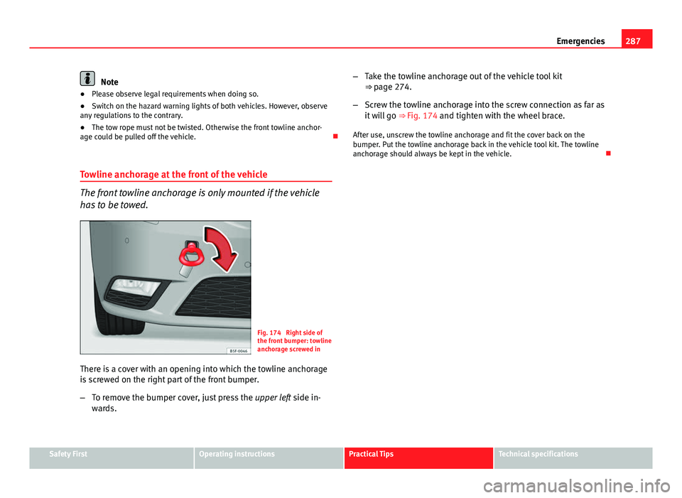
Fig. 174 Right side of
the front bumper: towline
anchorage screwed in
There is a cover with an opening into which the towline anchorage
is screwed on the right part of the front bumper.
– To remove the bumper cover, just press the upper left side in-
wards. –
Take the towline anchorage out of the vehicle tool kit
⇒ page 274.
– Screw the towline anchorage into the screw connection as far as
it will go ⇒ Fig. 174 and tighten with the wheel brace.
After use, unscrew the towline anchorage and fit the cover back on the
bumper. Put the towline anchorage back in the vehicle tool kit. The towline
anchorage should always be kept in the vehicle.
Safety FirstOperating instructionsPractical TipsTechnical specifications
Page 291 of 339
289
Emergencies
Tow-starting
As a general rule, tow-starting is not recommended.
– Engage 2nd or 3rd gear before moving off.
– Press the clutch and hold the pedal down.
– Switch the ignition on.
– Once both vehicles are moving, release the clutch.
– As soon as the engine starts: press the clutch and put the gear
lever in neutral.
If the engine will not start, it is best to try starting it using the battery of an-
other vehicle ⇒ page 283 before attempting to tow start. You should only try
to tow-start the engine if jump starting is not successful. Tow-starting is an
attempt to start the engine via the movement of the wheels.
When tow-starting a vehicle with a petrol engine, do not tow it more than a
short distance, otherwise unburned fuel can enter the catalytic converter
and cause damage.
WARNING
The risk of accidents is high when tow-starting, as the towed vehicle can
easily be driven into the towing vehicle.
CAUTION
Do not tow vehicles for more than 50 m. Risk of damage to the catalytic con-
verter. Towing vehicles with a manual gearbox
Towing is relatively straightforward.
Please observe the relevant instructions ⇒ page 286.
The vehicle can be towed using a tow bar or tow rope in the normal way,
with all four wheels on the road; it can also be towed with either the front or
rear wheels lifted off the road. The maximum towing speed is 50 km/h (30
mph).
Towing a vehicle equipped with automatic gearbox
Certain restrictions must be observed when towing your ve-
hicle. Please observe the relevant instructions ⇒ page 286.
The vehicle can be towed with a tow bar or tow rope in the normal way, with
all four wheels on the ground. When doing so, please note the following
points:
● Make sure the selector lever is in the N position.
● The vehicle must not be towed faster than 50 km/h (30 mph).
● The vehicle must not be towed further than 50 km (30 miles). Reason:
when the engine is not running, the gearbox oil pump does not work and
the gearbox is not adequately lubricated for higher speeds or longer distan-
ces.
If the vehicle has to be towed with a breakdown truck, it must only be sus-
pended at the front wheels. Reason: the drive shafts are located on the front
wheels. If the car is towed with the rear wheels lifted off the road (I.e. travel-
ling backwards), the drive shafts also turn backwards. The planetary gears
in the automatic gearbox then turn at such high speeds that the gearbox
will be severely damaged in a short time.
Safety FirstOperating instructionsPractical TipsTechnical specifications
Page 293 of 339

291
Fuses and bulbs
Fuses and bulbs Fuses
Introduction
Due to the constant update of vehicles, fuse assignments depending on
equipment and the use of the same fuse for various electrical components,
at the time of printing this manual it is not possible to provide an up-to-date
summary of the electrical components fuse positions. For detailed informa-
tion about the fuse positions, please consult a Technical Service.
In general, a fuse can be assigned to various electrical components. Like-
wise, an electrical component can be protected by several fuses.
Only replace fuses when the cause of the problem has been solved. If a
newly inserted fuse blows after a short time, you must have the electrical
system checked by a specialised workshop as soon as possible.
Additional information and warnings:
● Working in the engine compartment ⇒ page 251
WARNING
The high voltages in the electrical system can give serious electrical
shocks, causing burns and even death!
● Never touch the electrical wiring of the ignition system.
● Take care not to cause short circuits in the electrical system.
WARNING
Using unsuitable fuses, repairing fuses or bridging a current circuit with-
out fuses can cause a fire and serious injury.
● Never use a fuse with a higher value. Only replace fuses with a fuse of
the same amperage (same colour and markings) and size.
● Never repair a fuse.
● Never replace a fuse by a metal strip, staple or similar.
CAUTION
● To avoid damage to the vehicles electric system, before replacing a fuse
turn off the ignition, the lights and all electrical elements and remove the
keys from the ignition.
● If you replace a fuse with higher-rating fuse, you could cause damage to
another part of the electrical system.
● Protect the fuse boxes when open to avoid the entry of dust or humidity.
Dirt and humidity inside fuse boxes can cause damage to the electrical sys-
tem.
Note
● One single consumer could have more than one fuse.
● Several consumers could run over one single fuse.
Safety FirstOperating instructionsPractical TipsTechnical specifications
Page 295 of 339
293
Fuses and bulbs
Note
In the vehicle, there are more fuses than those indicated in this chapter.
These should only be changed by a specialised workshop.
Replacing a blown fuse
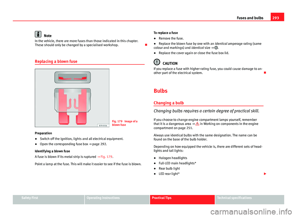
Fig. 179 Image of a
blown fuse
Preparation
● Switch off the ignition, lights and all electrical equipment.
● Open the corresponding fuse box ⇒ page 292.
Identifying a blown fuse
A fuse is blown if its metal strip is ruptured ⇒ Fig. 179.
Point a lamp at the fuse. This will make it easier to see if the fuse is blown. To replace a fuse
●
Remove the fuse.
● Replace the blown fuse by one with an identical amperage rating (same
colour and markings) and identical size ⇒
.
● Replace the cover again or close the fuse box lid.
CAUTION
If you replace a fuse with higher-rating fuse, you could cause damage to an-
other part of the electrical system.
Bulbs
Changing a bulb
Changing bulbs requires a certain degree of practical skill. If you choose to change engine compartment lamps yourself, remember
that it is a dangerous area ⇒
in Working on components in the engine
compartment on page 251.
Always use identical bulbs with the same designation. The name can be
found on the base of the bulb holder.
Depending on how equipped the vehicle is, there are different sets of head-
lights and tail lights:
● Halogen headlights
● Full-LED main headlights*
● Rear bulb light
● LED rear light*
Safety FirstOperating instructionsPractical TipsTechnical specifications
Page 297 of 339
295
Fuses and bulbs
Changing bulbs in headlight unit Dipped beam bulb
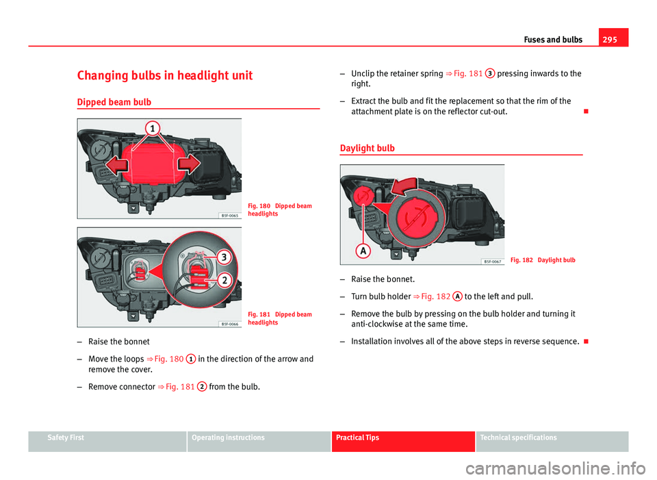
Fig. 180 Dipped beam
headlights
Fig. 181 Dipped beam
headlights
– Raise the bonnet
– Move the loops ⇒ Fig. 180 1
in the direction of the arrow and
remove the cover.
– Remove connector ⇒ Fig. 181 2
from the bulb. –
Unclip the retainer spring ⇒ Fig. 181 3
pressing inwards to the
right.
– Extract the bulb and fit the replacement so that the rim of the
attachment plate is on the reflector cut-out.
Daylight bulb
Fig. 182 Daylight bulb
– Raise the bonnet.
– Turn bulb holder ⇒ Fig. 182 A
to the left and pull.
– Remove the bulb by pressing on the bulb holder and turning it
anti-clockwise at the same time.
– Installation involves all of the above steps in reverse sequence.
Safety FirstOperating instructionsPractical TipsTechnical specifications
Page 299 of 339
297
Fuses and bulbs
Changing bulb for front fog light
Front fog light bulb
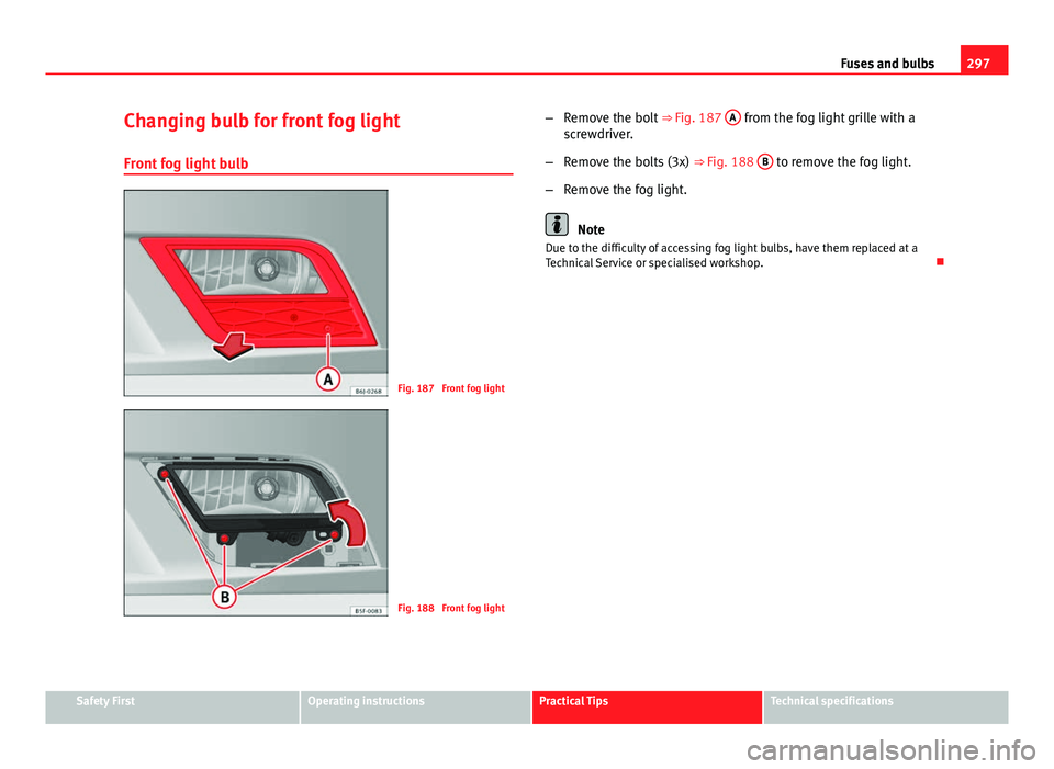
Fig. 187 Front fog light
Fig. 188 Front fog light –
Remove the bolt ⇒ Fig. 187 A
from the fog light grille with a
screwdriver.
– Remove the bolts (3x) ⇒ Fig. 188 B
to remove the fog light.
– Remove the fog light.
Note
Due to the difficulty of accessing fog light bulbs, have them replaced at a
Technical Service or specialised workshop.
Safety FirstOperating instructionsPractical TipsTechnical specifications
Page 301 of 339
299
Fuses and bulbs
– Remove the bulb by pressing on the bulb holder and turning it
anti-clockwise at the same time.
– Installation involves all of the above steps in reverse sequence.
– Check that the bulb works properly.
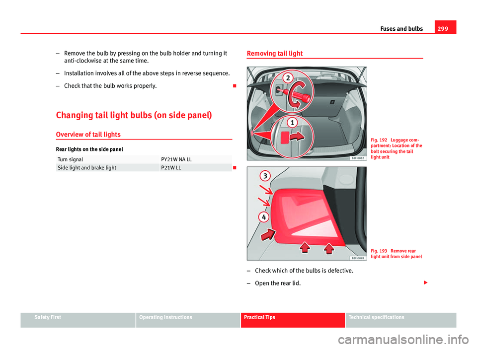
Changing tail light bulbs (on side panel) Overview of tail lights
Rear lights on the side panel
Turn signalPY21W NA LLSide light and brake lightP21W LL Removing tail light
Fig. 192 Luggage com-
partment: Location of the
bolt securing the tail
light unit
Fig. 193 Remove rear
light unit from side panel
– Check which of the bulbs is defective.
– Open the rear lid.
Safety FirstOperating instructionsPractical TipsTechnical specifications