ECO mode Seat Leon 5D 2015 Owner's manual
[x] Cancel search | Manufacturer: SEAT, Model Year: 2015, Model line: Leon 5D, Model: Seat Leon 5D 2015Pages: 308, PDF Size: 5.93 MB
Page 28 of 308
The essentials
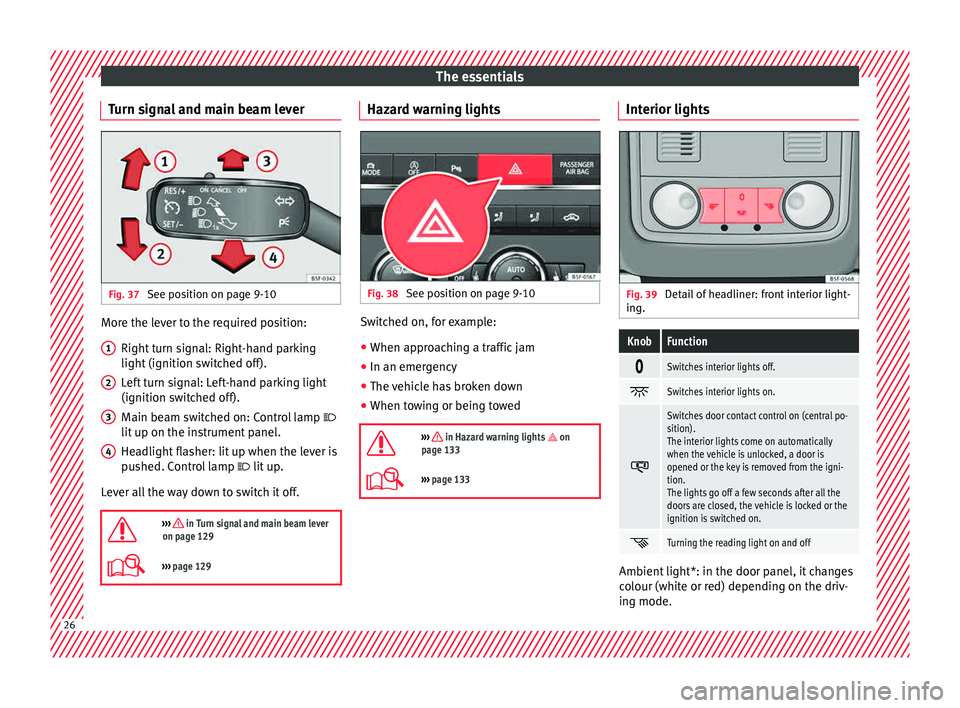
Turn signal and main beam lever Fig. 37
See position on page 9-10 More the lever to the required position:
Right t
urn s
ignal: Right-hand parking
light (ignition switched off).
Left turn signal: Left-hand parking light
(ignition switched off).
Main beam switched on: Control lamp
lit up on the instrument panel.
Headlight flasher: lit up when the lever is
pushed. Control lamp lit up.
Lever all the way down to switch it off.
››› in Turn signal and main beam lever
on page 129
››› page 129 1
2
3
4 Hazard warning lights
Fig. 38
See position on page 9-10 Switched on, for example:
● When approaching a traffic jam
● In an emergency
● The vehicle has broken down
● When towing or being towed
››› in Hazard warning lights on
page 133
››› page 133 Interior lights
Fig. 39
Detail of headliner: front interior light-
in g.
KnobFunction
Switches interior lights off.
Switches interior lights on.
Switches door contact control on (central po-
sition).
The interior lights come on automatically
when the vehicle is unlocked, a door is
opened or the key is removed from the igni-
tion.
The lights go off a few seconds after all the
doors are closed, the vehicle is locked or the
ignition is switched on.
Turning the reading light on and off
Ambient light*: in the door panel, it changes
c
o
lour (whit
e or red) depending on the driv-
ing mode. 26
Page 35 of 308
The essentialsMenuFunction
Audio
Station display on the radio.
Track name on the CD.
Track name in Media mode
››› Booklet Ra-
dio or ››› Booklet Navigation system.
Tele-
phoneInformation and possible configurations
of the mobile phone preinstallation
››› Booklet Radio or ››› Booklet Navigation
system.
Lap tim-
erIn a racing circuit, measurement and
memorisation of lap times by the vehicle
and comparison with previously measured
best times ››› page 37.
Vehicle
statusDisplay of the current warning or informa-
tion texts and other system components,
depending on the equipment
››› page 110. Outside temperature display
When the outside temperature is below +4°C
(+39°F), the “ic
e c
r
ystal” symbol (warning of
risk of freezing) is also displayed. At first, this
symbol flashes and then it remains lit until
the outside temperature rises above +6°C
(+43°F) ››› in Indications on the display on
p ag
e 106
.
When the vehicle is at a standstill or when
travelling at very low speeds, the tempera-
ture displayed may be higher than the true outside temperature as a result of the heat
produced b
y the engine.
The temperatures measured range from
-40°C to +50°C (-40°F to +122°F).
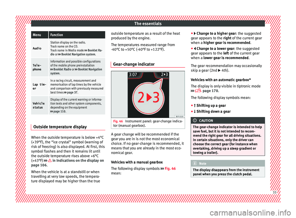
Gear-change indicator Fig. 46
Instrument panel: gear-change indica-
t or (m
anual
gearbox). A gear change will be recommended if the
g
e
ar
you are in is not the most economical
choice. If no gear-change is recommended, it
means that you are already in the most eco-
nomical gear.
Vehicles with a manual gearbox
The following display symbols ››› Fig. 46
mean: ●
Chang
e to a higher gear: the suggested
gear appears to the right of the current gear
when a higher gear is recommended .
● Change to a lower gear: the suggested
ge
ar appears to the left of the current gear
when a lower gear is recommended .
The gear recommendation may occasionally
skip a gear (2nd 4th).
Vehicles with an automatic gearbox*
The display is only visible in tiptronic mode
››› page 170.
The following display symbols mean:
● Shiftin g up a gear
●
Shifting down a gear CAUTION
The gear-change indicator is intended to help
sav e f
uel, but it is not intended to recom-
mend the right gear for all driving situations.
In certain situations, only the driver can
choose the correct gear (for instance when
overtaking, driving up a steep gradient or
towing a trailer). Note
The display disappears from the instrument
panel when
you press the clutch pedal. 33
Page 37 of 308
The essentials
Journey data M emor
y The MFD (multifunction display) shows differ-
ent
v
alues for the journey and the consump-
tion.
Changing between display modes on the
MFD
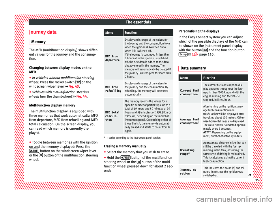
● In vehicles without multifunction steering
wheel:
Press the rocker switch on the
wind s
creen wiper lever ›››
Fig. 43.
● Vehicles with a multifunction steering
whee l:
turn the thumbwheel ›››
Fig. 44.
Multifunction display memory
The multifunction display is equipped with
three memories that work automatically: MFD
from departure, MFD from refuelling and MFD
total calculation. On the screen display, you
can read which memory is currently dis-
played.
● Toggle between memories with the ignition
on and the memory di
splayed: Press the
button on the windscreen wiper lever
or the button of the multifunction steering
wheel .
MenuFunction
MFD from
departure
Display and storage of the values for
the journey and the consumption from
when the ignition is switched on to
when it is switched off.
If the journey is continued in less than
2 hours after the ignition is switched
off, the new data is added to the data
already stored in the memory. The
memory will automatically be deleted if
the journey is interrupted for more than
2 hours.
MFD from refuellingDisplay and storage of the values for
the journey and the consumption. By
refuelling, the memory will be erased
automatically.
MFD total
calcula-
tion
The memory records the values for a
specific number of partial trips, up to a
total of 19 hours and 59 minutes or 99
hours and 59 minutes, or 1999.9 km or
9999 km, depending on the model of
instrument panel. On reaching either of
these limits a)
, the memory is automati-
cally erased and starts to count from 0
again.
a) It varies according to the instrument panel version.
Erasing a memory manually
● Select the memory that you wish to erase.
● Hold the button of the multifunction
s t
eerin
g wheel or the button of the multi-
f u nction wheel
pressed down for about 2 sec-
onds. Personalising the displays
In the Easy
Connect system you can adjust
which of the possible displays of the MFD can
be shown on the instrument panel display
with the button and the function button
Set up
› ››
p
age 110.
Dat
a summary
MenuFunction
Current fuel
consumption
The current fuel consumption dis-
play operates throughout the jour-
ney, in litres/100 km; and with the
engine running and the vehicle
stopped, in litres/hour.
Average fuel consumption a)
After turning on the ignition, aver-
age fuel consumption in li-
tres/100 km will be displayed after
travelling about 100 metres. Other-
wise horizontal lines are displayed.
The value shown is updated approxi-
mately every 5 seconds.
ACT®
*: Depending on the equip-
ment, number of active cylinders.
Operating range a)
Approximate distance in km that can
still be travelled with the fuel re-
maining in the tank, assuming the
same style of driving is maintained.
This is calculated using the current
fuel consumption.
Journey du-
rationThis indicates the hours (h) and mi-
nutes (min) since the ignition was
switched on.
» 35
Page 38 of 308
The essentialsMenuFunction
Distance
coveredDistance covered in km (m) after
switching on the ignition.
CNG quality
Whenever you refuel the quality of
the natural gas is automatically veri-
fied and is displayed when the igni-
tion is switched on. The display is
made in a percentage of between
70% and 100%. The greater the per-
centage displayed the lower the con-
sumption may be.
Average
speed
The average speed will be shown af-
ter a distance of about 100 metres
has been travelled. Otherwise hori-
zontal lines are displayed. The value
shown is updated approximately ev-
ery 5 seconds.
Digital dis- play of
speedCurrent speed displayed in digital
format.
Speed warn-
ing at ---
km/h or Speed
warning at
--- mphIf the stored speed is exceeded (be-
tween 30 - 250 km/h, or 19 -
155 mph), an audible warning is
given together with a visual warn-
ing.
Detection of
traffic
signsThe traffic signs detected are dis-
played.
Oil tempera- tureUpdated engine oil temperature dig-
ital display
MenuFunction
Coolant tem-perature
gaugeDigital display of the current temper-
ature of the liquid coolant.
a) In vehicles with a natural gas engine, range and average con-
sumption refer only to data or natural gas consumption. If you
are in “petrol mode”, the information of both data only appears
on the dash panel and not on the multifunction screen.
Storing a speed with the speed warning
● Select the display Speed warning at
--- km/h (---
mph)
● Press the button
on the windscreen
w iper l
ev
er or the button on the multifunc-
tion s t
eerin
g wheel to store the current speed
and activate the warning.
● To switch system on: adjust to the desired
speed within 5 sec
onds using the rocker
switch on the windscreen wiper lever or
b y
t
urning the thumbwheel on the multifunc-
tion steering wheel. Next, press the button or
again or wait several seconds.
The s peed i
s
stored and the warning activa-
ted.
● To switch system off: press the but-
ton or
. The stored speed is de-
l et
ed. En
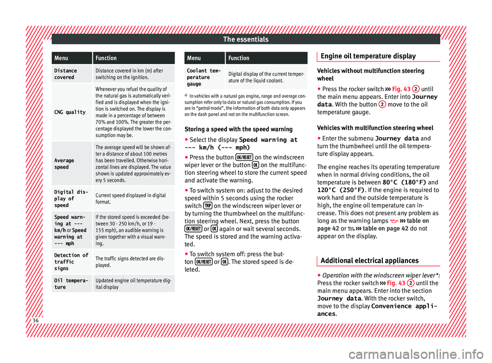
gine oil temperature display Vehicles without multifunction steering
wheel
● Press the rocker switch ›››
Fig. 43 2 until
the main menu ap pe
ars. Enter into Journey
data . With the button 2 move to the oil
temper at
ure gauge.
Vehicles with multifunction steering wheel
● Enter the submenu Journey data and
turn the thumbwheel
until the oil tempera-
ture display appears.
The engine reaches its operating temperature
when in normal driving conditions, the oil
temperature is between 80°C (180°F) and
120°C (250°F) . If the engine is required to
work hard and the outside temperature is
high, the engine oil temperature can in-
crease. This does not present any problem as
long as the warning lamps ›››
table on
page 42 or ›››
table on page 42 do not
appear on the display.
Additional electrical appliances ●
Operation with the windscreen wiper lever*:
Pr e
s
s the rocker switch ›››
Fig. 43 2 until the
m ain menu ap
pe
ars. Enter into the section
Journey data . With the rocker switch,
move to the display Convenience appli-
ances .36
Page 41 of 308
The essentials
you only need to change the oil when the ve-
hic l
e so r
equires. To calculate this change
(max. 2 years), the vehicle's conditions of
use and individual driving styles are consid-
ered. The pre-warning first appears 20 days
before the date established for the corre-
sponding service. The kilometres (miles) re-
maining until the next service are always
rounded up to the nearest 100 km (miles)
and the time is given in complete days. The
current service message cannot be viewed
until 500 km after the last service. Prior to
this, only lines are visible on the display.
Inspection reminder
When the Service date is approaching, when
the ignition is switched on a Service remind-
er is displayed.
Vehicles without text messages : a span-
ner will be displayed on the instrument
panel plus an indication in km.
The kilometres indicated are the maximum
number of kilometres that can be travelled
until the next service. After a few seconds,
the display mode changes. A clock symbol
appears and the number of days until the
next service is due.
Vehicles with text messages : Service in
--- km or --- days will be shown on the
instrument panel display. Service due
When the servic
e date is due, an audible
warning is given when the ignition is switch-
ed on and the spanner displayed on the
screen flashes for a few seconds .
Vehicles with text messages : Service now
will be shown on the instrument panel dis-
play.
Reading a service notification
With the ignition switched on, the engine off
and the vehicle at a standstill, the current
service notification can be read:
Press and hold the button ›››
Fig. 124
4 for more than 5 seconds to consult the serv-
ic
e me
s
sage.
When the service date has passed , a minus
sign is displayed in front of the number of kil-
ometres or days.
Vehicles with text messages : the following
message is displayed: Service --- km
(miles) or --- days ago .
The time can also be set via the key and
Set up function button in the Easy Connect
sy s
t
em ›››
page 110.
Resetting service interval display
If the service was not carried out by a SEAT
dealership, the display can be reset as fol-
lows: ●
Switc
h off the ignition, press and hold but-
ton ›››
Fig. 124
4 .
● Switch ignition back on.
● Release THE 4
› ››
Fig. 124
b
utton and
press it again for the next 20 seconds. Note
● The serv ic
e message disappears after a few
seconds, when the engine is started or when OK/RESET is pressed on the windscreen wiper
lev er
, or OK on the multifunction steering
wheel.
● In v
ehicles with the LongLife system in
which the batt
ery has been disconnected for
a long period of time, it is not possible to cal-
culate the date of the next service. Therefore
the service interval display may not be cor- rect. In this case, bear in mind the maximum
service intervals permitted in the ››› Book-
let Maintenance Programme.
● If you reset the display manually, the next
servic
e interval will be indicated as in vehi-
cles with fixed service intervals. For this rea-
son we recommend that the service interval
display be reset by a SEAT authorised service. 39
Page 74 of 308
Safety
Seat belts
Wh y
w
ear a seat belt?
Number of seats Your vehicle has
five se
ats, two in the front
and three in the rear. Each seat is equipped
with a three-point seat belt.
In some versions, your vehicle is approved
only for four seats. Two front seats and two
rear seats. WARNING
● Never tr an
sport more than the permitted
amount of people in your vehicle.
● Every vehicle occupant must properly fas-
ten and we
ar the seat belt belonging to his or
her seat. Children must be protected with an
appropriate child restraint system. Seat belt lamp*
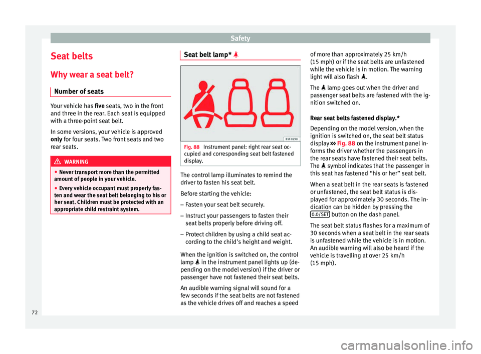
Fig. 88
Instrument panel: right rear seat oc-
c upied and c
orr
esponding seat belt fastened
display. The control lamp illuminates to remind the
driv
er t
o f
asten his seat belt.
Before starting the vehicle: – Fasten your seat belt securely.
– Instruct your passengers to fasten their
seat belts
properly before driving off.
– Protect children by using a child seat ac-
cordin
g to the child's height and weight.
When the ignition is switched on, the control
lamp in the instrument panel lights up (de-
pending on the model version) if the driver or
passenger have not fastened their seat belts.
An audible warning signal will sound for a
few seconds if the seat belts are not fastened
as the vehicle drives off and reaches a speed of more than approximately 25 km/h
(15 mph) or if the seat
belts are unfastened
while the vehicle is in motion. The warning
light will also flash .
The lamp goes out when the driver and
passenger seat belts are fastened with the ig-
nition switched on.
Rear seat belts fastened display.*
Depending on the model version, when the
ignition is switched on, the seat belt status
display ››› Fig. 88 on the instrument panel in-
forms the driver whether the passengers in
the rear seats have fastened their seat belts.
The symbol indicates that the passenger in
this seat has fastened “his or her” seat belt.
When a seat belt in the rear seats is fastened
or unfastened, the seat belt status is dis-
played for approximately 30 seconds. The in-
dication can be hidden by pressing the 0.0/SET button on the dash panel.
The se at
belt
status flashes for a maximum of
30 seconds when a seat belt in the rear seats
is unfastened while the vehicle is in motion.
An audible warning will also be heard if the
vehicle is travelling at over 25 km/h
(15 mph).
72
Page 87 of 308

Transporting children safely
●
When a chi l
d seat is mounted in the rear
seats, the door child-proof lock should be ac-
tivated ››› page 121. Child seats
Safety in
structionsRead the additional information carefully
›› ›
page 20. WARNING
When travelling, children must be secured in
the v ehic
le with a restraint system suitable
for age, weight and size.
● Read and always observe information and
warning
s concerning the use of child seats
››› page 84. WARNING
The retaining rings are designed only for use
with “ISOFIX” and T op
Tether* system child
seats.
● Never secure other child seats that do not
have the “ISOFIX” or T
op Tether* system, or
retaining belts or objects to the fastening
rings - this can result in potentially fatal inju-
ries to the child.
● Ensure that the child seat is secured cor-
rectly u
sing the “ISOFIX” and Top Tether* se-
curing rings. WARNING
An undue installation of the safety seat will
incr e
ase the risk of injury in the event of a
crash.
● Never tie the retainer strap to a hook in the
luggag
e compartment.
● Never secure or tie luggage or other items
to the low
er anchorages (ISOFIX) or the upper
ones (Top Tether). Categorisation of child seats into
gr
oup
s Use only child seats that are officially ap-
pr
o
v
ed and suitable for the child.
Child seats are subject to the regulation ECE-
R 44. ECE-R stands for: Economic Commis-
sion for Europe Regulations.
The child seats are grouped into 5 catego-
ries:
Group 0: Up to 10 kg (up to around 9
months)
Group 0+: Up to 13 kg (up to around 18
months)
Group 1: from 9 to 18 kg (up to approx. 4
years old)
Group 2: from 15 to 25 kg (up to approx. 7
years old) Group 3: From 22 to 36 kg (over around 7
ye
ars old)
Child seats that have been tested and ap-
proved under the ECE R44 standard bear the
test mark on the seat (the letter E in a circle
with the test number below it).
Follow the manufacturer's instructions and
observe any statutory requirements when in-
stalling and using child seats.
We recommend you to always include the
manufacturer's Child Seat Instruction Manual
together with the on-board documentation.
SEAT recommends you use child seats from
the Original Accessories Catalogue . These
child seats have been designed and tested
for use in SEAT vehicles. You can find the
right child seat for your model and age group
at SEAT dealers.
85
Technical data
Advice
Operation
Emergencies
Safety
Page 108 of 308
Operation
● Keep the b
utt
on 4 pressed for about 3
sec ond
s
and the previous value will be dis-
played.
Time
● To set the time, keep the button ›››
Fig. 124
4 pressed for more than 3 seconds to select
the hour or minut e di
s
play.
● To continue setting the time, press the up-
per or lower p
art of the button 4 . Hold but-
t on do
wn t
o scroll through the numbers
quickly.
● Press the button 4 again in order to finish
settin g the time.
The time c an al
so be set via the key and
Set up function button in the Easy Connect
sy s
t
em ››› page 110.
Compass
With the ignition on and the navigation sys-
tem on, the cardinal point corresponding to
the direction of travel of the vehicle is dis-
played on the instrument panel.
Selector lever position
The selected gear is displayed on the side of
the selector lever and on the instrument pan-
el display. In positions D and S, and with the
Tiptronic, the corresponding gear is also dis-
played. Recommended gear (manual gearbox)
The recommended g
ear in order to save fuel
is displayed on the instrument panel while
you are driving ›››
page 33.
Second speed display (mph or km/h)
In addition to the speedometer, the speed
can also be displayed in a different unit of
measurement (in miles or in km per hour).
This option cannot be deactivated in models
destined for countries in which the second
speed must always be visible.
The second speed display can be adjusted in
the Easy Connect system via the key and
the Set
up function button
››
›
page 110.
Speed warning
When the speed setting is exceeded, this will
be indicated on the instrument panel display.
This is very useful, for example when using
winter tyres that are not designed for driving
at the maximum speed of the vehicle
››› page 38.
The speed warning settings can be adjusted
in the Easy Connect system via the key
and the Set
up function button
››
›
page 110.
Start-Stop operating display
Updated information relating to the status is
displayed on the instrument panel
››› page 183. Low consumption driving status (ECO)*
Depending on the equipment, when driv
ing,
the “ECO ” display appears on the instrument
panel when the vehicle is in low consump-
tion status due to active cylinder manage-
ment (ACT ®
)* ››› page 177.
Identifying letters on engine (MKB)
Hold the button ››› Fig. 124 4 down for more
th an 15 sec
ond
s to display the identifying
letters of the vehicle engine (MKB). To do
this, the ignition must be switched on and
the engine switched off. WARNING
Observe the safety warnings ›››
in Warning
and indication l amp
s on page 109. WARNING
Even though outside temperatures are above
freez in
g, some roads and bridges may be icy.
● At outside temperatures above +4°C
(+39°F), even when the “ice c
rystal symbol”
is not visible, there may still be patches of ice
on the road.
● Do not rely on the outside temperature in-
dicator! Note
● Differ ent
versions of the instrument panel
are available and therefore the versions and 106
Page 136 of 308
Operation
Motorway light* The motorway light is available on vehicles
equipped w
ith f
ull-LED lights.
The function is connected/disconnected via
the corresponding Easy Connect system
menu.
● Activation: when going abo
ve 110 km/h for
more than 30 seconds, the dipped beam rai-
ses slightly to increase the distance of visibil-
ity of the driver.
● Deactivation: when reduc in
g the speed of
the car below 100 km/h, the dipped beam re-
turns to its normal position.
Driving abroad The light beam of the dipped beam lights is
a
symmetric: the s
ide of
the road on which
you are driving is lit more intensely.
When a car that is manufactured in a country
that drives on the right travels to a country
that drives on the left (or vice versa), it is nor-
mally necessary to cover part of the headlight
bulbs with stickers or to change the adjust-
ment of the headlights to avoid dazzling oth-
er drivers.
In such cases, the regulations specify certain
light values that must be complied with for
designated points of the light distribution.
This is known as “Tourist light”. The light distribution that the halogen and
ful
l-LED headlights of the SEAT Leon range
have allows the specific “tourist light” values
to be met without the need for stickers or
changes in the settings. Note
“Tourist light” is only allowed temporarily. If
you ar e p
lanning a long stay in a country that
drives on the other side, you should take the
vehicle to an Authorised Technical Service to
change the headlights. Headlight range control, lighting of
the in
s
trument
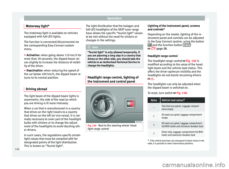
and control panel Fig. 140
Next to the steering wheel: Head-
light r
an
ge control Lighting of the instrument panel, screens
and c
ontr
o
ls*
Depending on the model, lighting of the in-
strument panel and controls can be adjusted
in the Easy Connect system, using the button and the function button
S
ETUP ›››
p
age 28.
He a
dlight range control
The headlight range control ››› Fig. 140 is
modified according to the value of the head-
light beam and the vehicle load status. This
offers the driver optimum visibility and the
headlights do not dazzle oncoming drivers
››› .
The he a
dlights
can only be adjusted when
the dipped beam is switched on.
To reset, turn switch ››› Fig. 140:
ValueVehicle load status a)
–Two front occupants, luggage compart-
ment empty
1All seats occupied, luggage compartment
empty
2All seats occupied, luggage compartment
full With trailer and minimum drawbar load
3Driver only, luggage compartment full With
trailer and maximum drawbar load
a)
If the vehicle load does not correspond to those shown in the
table, it is possible to select intermediary positions.
134
Page 138 of 308

Operation
Options for adjusting driver and front pas-
sen g
er s
un visors:
● Lower the sun visor towards the wind-
scr
een.
● The sun visor can be pulled out of its
mounting and t
urned towards the door
››› Fig. 141 1 .
● Swing the sun visor towards the door, lon-
git udin
al
ly backwards.
Vanity mirror light
There may be a vanity mirror, with a cover, on
the rear of the sun visor. When the cover is
opened 2 a light comes on.
The l amp g
oe
s out when the vanity mirror
cover is closed or the sun visor is pushed
back up. WARNING
Folded sun blinds can reduce visibility.
● Always store sun blinds and visors in their
hous in
g when not in use. Note
The light above the sun visor automatically
swit c
hes off after a few minutes in certain
conditions. This prevents the battery from
discharging. Sun blind*
3 Applies to the model: LEON ST
Fig. 142
Rear window: sun blind. Rear window sun blind*
– Pull out the visor and hook it into the hooks
in the c entr
e of
the top of the door frame
››› Fig. 142.
Windscreen wiper and window
wiper sys
tems
Window wiper lever Read the additional information carefully
› ›
›
page 27 CAUTION
If the ignition is switched off with the wind-
sc r
een wipers active, they complete their wipe before returning to the rest position.
Ice, s
no
w and other obstacles on the wind-
screen may damage the wiper and the wind-
screen wiper motor.
● If necessary, remove snow and ice from the
winds
creen wipers before starting your jour-
ney.
● Carefully lift the frozen windscreen wipers
from the gla
ss. SEAT recommends a de-icer
spray for this operation.
● Do not switch on the windscreen wipers if
the winds
creen is dry. Cleaning with the
windscreen wipers while dry can cause dam-
age.
● In icy conditions, always check that the
wiper bl
ades are not frozen to the glass be-
fore using the wipers. In cold weather, it may
help to leave the vehicle parked with the wip-
ers in service position ›››
page 64. Note
● The wind s
creen and window wipers only
function when the ignition is switched on and
the bonnet or rear lid, respectively, are
closed.
● The interval wipe speed varies according to
the vehic
le speed. The faster the vehicle is
moving, the more often the windscreen is
cleaned.
● The rear wiper is automatically switched on
when the winds
creen wiper is on and the car
is in reverse gear. 136