fuel Seat Leon 5D 2015 Owner's manual
[x] Cancel search | Manufacturer: SEAT, Model Year: 2015, Model line: Leon 5D, Model: Seat Leon 5D 2015Pages: 308, PDF Size: 5.93 MB
Page 8 of 308
Table of Contents
Monitoring system Front Assist* . . . . . . . . . . . . 197
Lane Assist system* . . . . . . . . . . . . . . . . . . . . . . 202
SEAT Drive Profile* . . . . . . . . . . . . . . . . . . . . . . . 204
Traffic sign detection system . . . . . . . . . . . . . . . 208
Tiredness detection (break recommenda-
tion)* . . . . . . . . . . . . . . . . . . . . . . . . . . . . . . . . . .
210
P ark
ing aid . . . . . . . . . . . . . . . . . . . . . . . . . . . . . 211
Rear Assist “Rear View Camera”* . . . . . . . . . . . 217
Towing bracket device . . . . . . . . . . . . . . . . . . . . 220
Towing bracket device* . . . . . . . . . . . . . . . . . . . 220
Trailer towing . . . . . . . . . . . . . . . . . . . . . . . . . . . 225
Advice . . . . . . . . . . . . . . . . . . . . . . . . . . . . . . . . 230
Care and maintenance . . . . . . . . . . . . . . . . . . . . 230
Accessories and modifications to the vehi-
cle
. . . . . . . . . . . . . . . . . . . . . . . . . . . . . . . . . . . . 230
Care and cleaning . . . . . . . . . . . . . . . . . . . . . . . 231
Vehicle exterior care . . . . . . . . . . . . . . . . . . . . . . 231
Caring for the vehicle interior . . . . . . . . . . . . . . 235
Intelligent technology . . . . . . . . . . . . . . . . . . . . 238
Electromechanical steering . . . . . . . . . . . . . . . . 238
Progressive steering . . . . . . . . . . . . . . . . . . . . . 238
Four-wheel drive . . . . . . . . . . . . . . . . . . . . . . . . . 239
Power Management . . . . . . . . . . . . . . . . . . . . . . 239
Checking and refilling levels . . . . . . . . . . . . . . . 241
Filling the tank . . . . . . . . . . . . . . . . . . . . . . . . . . 241
Fuel . . . . . . . . . . . . . . . . . . . . . . . . . . . . . . . . . . . 243
Engine compartment . . . . . . . . . . . . . . . . . . . . . 246
Engine oil . . . . . . . . . . . . . . . . . . . . . . . . . . . . . . 248
Cooling system . . . . . . . . . . . . . . . . . . . . . . . . . . 250
Brake fluid . . . . . . . . . . . . . . . . . . . . . . . . . . . . . 251
Windscreen washer reservoir . . . . . . . . . . . . . . 252
Battery . . . . . . . . . . . . . . . . . . . . . . . . . . . . . . . . . 253
Wheels . . . . . . . . . . . . . . . . . . . . . . . . . . . . . . . . 255
Wheels and tyres . . . . . . . . . . . . . . . . . . . . . . . . 255
Tyre monitoring systems . . . . . . . . . . . . . . . . . . 259
Temporary spare wheel . . . . . . . . . . . . . . . . . . . 262
Winter service . . . . . . . . . . . . . . . . . . . . . . . . . . . 263 Technical data
. . . . . . . . . . . . . . . . . . . . . . . . 265
Technical specifications . . . . . . . . . . . . . . . . . . 265
Important . . . . . . . . . . . . . . . . . . . . . . . . . . . . . . 265
Vehicle identification data . . . . . . . . . . . . . . . . . 265
Information on fuel consumption . . . . . . . . . . . 266
Driving with a trailer . . . . . . . . . . . . . . . . . . . . . . 267
Wheels . . . . . . . . . . . . . . . . . . . . . . . . . . . . . . . . 267
Engine data . . . . . . . . . . . . . . . . . . . . . . . . . . . . . 269
Dimensions . . . . . . . . . . . . . . . . . . . . . . . . . . . . . 292
Index . . . . . . . . . . . . . . . . . . . . . . . . . . . . . . . . . 293
6
Page 33 of 308
The essentials
Driver information system Intr oduction With the ignition switched on, it is possible
to r
e
ad the different functions of the display
by scrolling through the menus.
In vehicles with multifunction steering wheel,
the multifunction display can only be operat-
ed with the steering wheel buttons.
The number of menus displayed on the in-
strument panel will vary according to the ve-
hicle electronics and equipment.
A specialised workshop will be able to pro-
gramme or modify additional functions, ac-
cording to the vehicle equipment. SEAT rec-
ommends visiting a SEAT Official Service.
Some menu options can only be read when
the vehicle is at a standstill.
As long as a priority 1 warning is displayed, it
will not be possible to read the menus. Some
warning messages can be confirmed and
made to disappear with the windscreen wiper
lever button or the multifunction steering
wheel button.
The information system also provides the fol-
lowing information and displays (depending
on the vehicle's equipment):
Driving data ›››
page 35
■ Vehicle status ■
MFD from dep ar
ture
■ MFD from refuelling
■ MFD total calculation
Assist systems ››› table on page 32
■ Activate/deactivate Lane Assist
■ Reverse (optional)
Navigation ››› Booklet Navigation system
Audio ››› Booklet Radio or ››› Booklet Naviga-
tion system
Telephone ››› Booklet Radio or ››› Book-
let Navigation system
Vehicle ››› table on page 32 WARNING
Any distraction may lead to an accident, with
the risk of
injury.
● Do not operate the instrument panel con-
trol
s when driving. Using the menus on the instrument
p
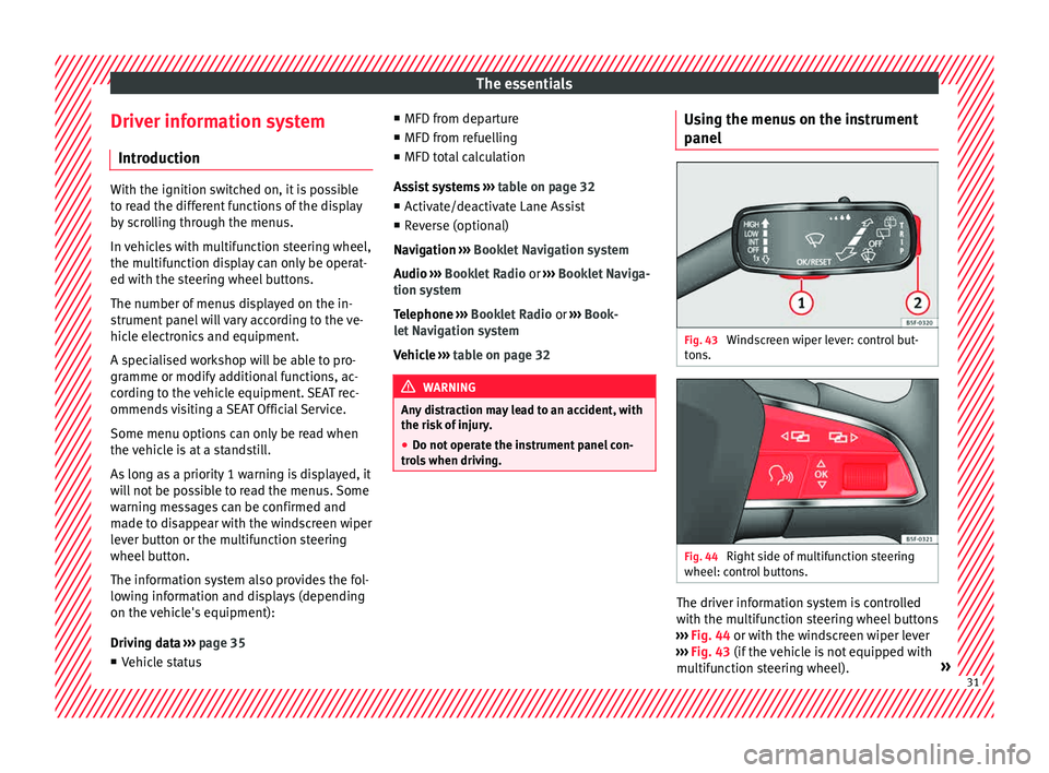
anel Fig. 43
Windscreen wiper lever: control but-
t on
s. Fig. 44
Right side of multifunction steering
wheel: c ontr
o
l buttons. The driver information system is controlled
w
ith the mu
ltif
unction steering wheel buttons
››› Fig. 44 or with the windscreen wiper lever
››› Fig. 43 (if the vehicle is not equipped with
multifunction steering wheel). » 31
Page 37 of 308
The essentials
Journey data M emor
y The MFD (multifunction display) shows differ-
ent
v
alues for the journey and the consump-
tion.
Changing between display modes on the
MFD
● In vehicles without multifunction steering
wheel:
Press the rocker switch on the
wind s
creen wiper lever ›››
Fig. 43.
● Vehicles with a multifunction steering
whee l:
turn the thumbwheel ›››
Fig. 44.
Multifunction display memory
The multifunction display is equipped with
three memories that work automatically: MFD
from departure, MFD from refuelling and MFD
total calculation. On the screen display, you
can read which memory is currently dis-
played.
● Toggle between memories with the ignition
on and the memory di
splayed: Press the
button on the windscreen wiper lever
or the button of the multifunction steering
wheel .
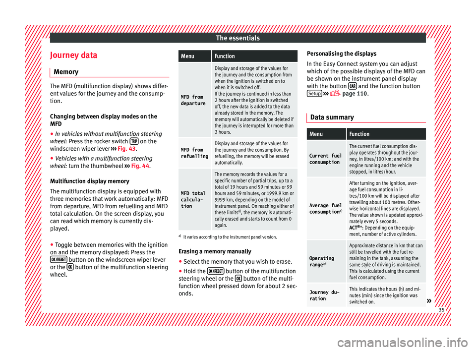
MenuFunction
MFD from
departure
Display and storage of the values for
the journey and the consumption from
when the ignition is switched on to
when it is switched off.
If the journey is continued in less than
2 hours after the ignition is switched
off, the new data is added to the data
already stored in the memory. The
memory will automatically be deleted if
the journey is interrupted for more than
2 hours.
MFD from refuellingDisplay and storage of the values for
the journey and the consumption. By
refuelling, the memory will be erased
automatically.
MFD total
calcula-
tion
The memory records the values for a
specific number of partial trips, up to a
total of 19 hours and 59 minutes or 99
hours and 59 minutes, or 1999.9 km or
9999 km, depending on the model of
instrument panel. On reaching either of
these limits a)
, the memory is automati-
cally erased and starts to count from 0
again.
a) It varies according to the instrument panel version.
Erasing a memory manually
● Select the memory that you wish to erase.
● Hold the button of the multifunction
s t
eerin
g wheel or the button of the multi-
f u nction wheel
pressed down for about 2 sec-
onds. Personalising the displays
In the Easy
Connect system you can adjust
which of the possible displays of the MFD can
be shown on the instrument panel display
with the button and the function button
Set up
› ››
p
age 110.
Dat
a summary
MenuFunction
Current fuel
consumption
The current fuel consumption dis-
play operates throughout the jour-
ney, in litres/100 km; and with the
engine running and the vehicle
stopped, in litres/hour.
Average fuel consumption a)
After turning on the ignition, aver-
age fuel consumption in li-
tres/100 km will be displayed after
travelling about 100 metres. Other-
wise horizontal lines are displayed.
The value shown is updated approxi-
mately every 5 seconds.
ACT®
*: Depending on the equip-
ment, number of active cylinders.
Operating range a)
Approximate distance in km that can
still be travelled with the fuel re-
maining in the tank, assuming the
same style of driving is maintained.
This is calculated using the current
fuel consumption.
Journey du-
rationThis indicates the hours (h) and mi-
nutes (min) since the ignition was
switched on.
» 35
Page 38 of 308
The essentialsMenuFunction
Distance
coveredDistance covered in km (m) after
switching on the ignition.
CNG quality
Whenever you refuel the quality of
the natural gas is automatically veri-
fied and is displayed when the igni-
tion is switched on. The display is
made in a percentage of between
70% and 100%. The greater the per-
centage displayed the lower the con-
sumption may be.
Average
speed
The average speed will be shown af-
ter a distance of about 100 metres
has been travelled. Otherwise hori-
zontal lines are displayed. The value
shown is updated approximately ev-
ery 5 seconds.
Digital dis- play of
speedCurrent speed displayed in digital
format.
Speed warn-
ing at ---
km/h or Speed
warning at
--- mphIf the stored speed is exceeded (be-
tween 30 - 250 km/h, or 19 -
155 mph), an audible warning is
given together with a visual warn-
ing.
Detection of
traffic
signsThe traffic signs detected are dis-
played.
Oil tempera- tureUpdated engine oil temperature dig-
ital display
MenuFunction
Coolant tem-perature
gaugeDigital display of the current temper-
ature of the liquid coolant.
a) In vehicles with a natural gas engine, range and average con-
sumption refer only to data or natural gas consumption. If you
are in “petrol mode”, the information of both data only appears
on the dash panel and not on the multifunction screen.
Storing a speed with the speed warning
● Select the display Speed warning at
--- km/h (---
mph)
● Press the button
on the windscreen
w iper l
ev
er or the button on the multifunc-
tion s t
eerin
g wheel to store the current speed
and activate the warning.
● To switch system on: adjust to the desired
speed within 5 sec
onds using the rocker
switch on the windscreen wiper lever or
b y
t
urning the thumbwheel on the multifunc-
tion steering wheel. Next, press the button or
again or wait several seconds.
The s peed i
s
stored and the warning activa-
ted.
● To switch system off: press the but-
ton or
. The stored speed is de-
l et
ed. En
gine oil temperature display Vehicles without multifunction steering
wheel
● Press the rocker switch ›››
Fig. 43 2 until
the main menu ap pe
ars. Enter into Journey
data . With the button 2 move to the oil
temper at
ure gauge.
Vehicles with multifunction steering wheel
● Enter the submenu Journey data and
turn the thumbwheel
until the oil tempera-
ture display appears.
The engine reaches its operating temperature
when in normal driving conditions, the oil
temperature is between 80°C (180°F) and
120°C (250°F) . If the engine is required to
work hard and the outside temperature is
high, the engine oil temperature can in-
crease. This does not present any problem as
long as the warning lamps ›››
table on
page 42 or ›››
table on page 42 do not
appear on the display.
Additional electrical appliances ●
Operation with the windscreen wiper lever*:
Pr e
s
s the rocker switch ›››
Fig. 43 2 until the
m ain menu ap
pe
ars. Enter into the section
Journey data . With the rocker switch,
move to the display Convenience appli-
ances .36
Page 39 of 308
The essentials
● Oper ation with
the
multi-function steering
wheel*: Move with the buttons 1 or
2 to
Journey data and enter w
ith
OK . Turn the
thumbwheel to the right until the Conven-
ience appliances display appears.
In addition, a scale will inform you of the cur-
rent sum of all the additional appliances.
Saving tips Tips on how to save fuel will be displayed in
c
ondition
s
that increase fuel consumption.
Follow them to reduce consumption. The indi-
cations appear automatically only with the ef-
ficiency programme. After a time, the tips will
disappear automatically.
If you wish to hide a saving tip immediately
after it appears, press any button on the
windscreen wiper lever*/multifunction steer-
ing wheel*. Note
● If y
ou hide a saving tip, it will reappear af-
ter you switch the ignition on again.
● The saving tips do not appear in all situa-
tions, but
rather with a large separation of
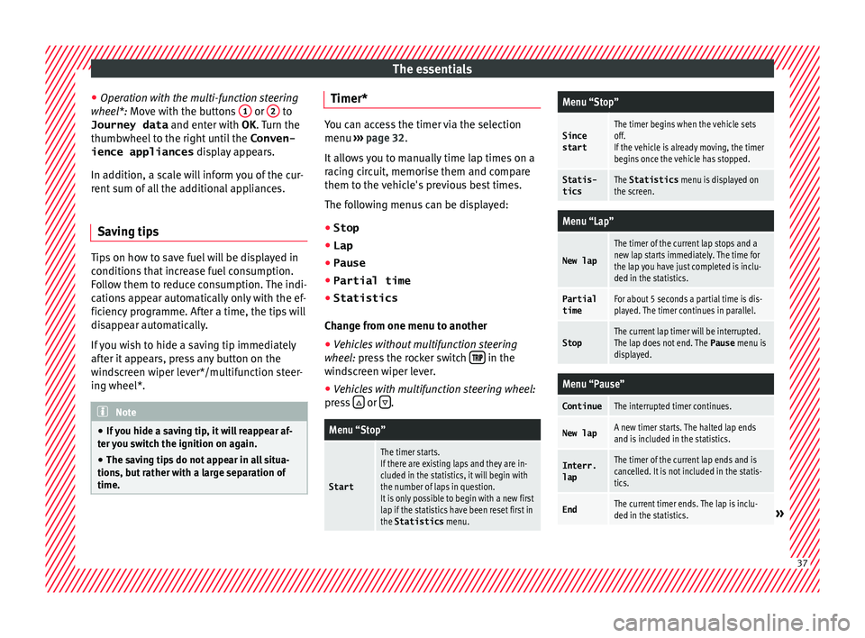
time. Timer*
You can access the timer via the selection
menu
›››
page 32.
It allows you to manually time lap times on a
racing circuit, memorise them and compare
them to the vehicle's previous best times.
The following menus can be displayed:
● Stop
● Lap
● Pause
● Partial time
● Statistics
Chang
e from one menu to another
● Vehicles without multifunction steering
whee l:
press the rocker switch in the
w ind
s
creen wiper lever.
● Vehicles with multifunction steering wheel:
pres
s or
.
Menu “Stop”
Start
The timer starts.
If there are existing laps and they are in-
cluded in the statistics, it will begin with
the number of laps in question.
It is only possible to begin with a new first
lap if the statistics have been reset first in
the Statistics
menu.
Menu “Stop”
Since
startThe timer begins when the vehicle sets
off.
If the vehicle is already moving, the timer
begins once the vehicle has stopped.
Statis-
ticsThe Statistics menu is displayed on
the screen.
Menu “Lap”
New lap
The timer of the current lap stops and a
new lap starts immediately. The time for
the lap you have just completed is inclu-
ded in the statistics.
Partial timeFor about 5 seconds a partial time is dis-
played. The timer continues in parallel.
StopThe current lap timer will be interrupted.
The lap does not end. The Pause menu is
displayed.
Menu “Pause”
ContinueThe interrupted timer continues.
New lapA new timer starts. The halted lap ends
and is included in the statistics.
Interr. lapThe timer of the current lap ends and is
cancelled. It is not included in the statis-
tics.
EndThe current timer ends. The lap is inclu-
ded in the statistics.» 37
Page 44 of 308
The essentials
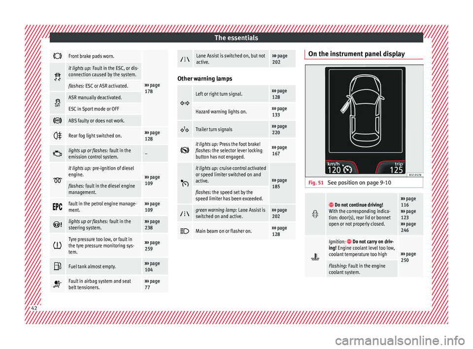
Front brake pads worn.
›››
page
178
it lights up:
Fault in the ESC, or dis-
connection caused by the system.
flashes: ESC or ASR activated.
ASR manually deactivated.
ESC in Sport mode or OFF
ABS faulty or does not work.
Rear fog light switched on.›››
page
128
lights up or flashes:
fault in the
emission control system.–
it lights up:
pre-ignition of diesel
engine.
››› page
109
flashes: fault in the diesel engine
management.
fault in the petrol engine manage-
ment.›››
page
109
lights up or flashes:
fault in the
steering system.››› page
238
Tyre pressure too low, or fault in
the tyre pressure monitoring sys-
tem.›››
page
259
Fuel tank almost empty.›››
page
104
Fault in airbag system and seat
belt tensioners.›››
page
77
Lane Assist is switched on, but not
active.›››
page
202 Other warning lamps
Left or right turn signal.›››
page
128
Hazard warning lights on.››› page
133
Trailer turn signals›››
page
220
it lights up:
Press the foot brake!
flashes: the selector lever locking
button has not engaged.››› page
167
it lights up:
cruise control activated
or speed limiter switched on and
active.
››› page
185
flashes: the speed set by the
speed limiter has been exceeded.
green warning lamp: Lane Assist is
switched on and active.›››
page
202
Main beam on or flasher on.›››
page
128 On the instrument panel display
Fig. 51
See position on page 9-10
Do not continue driving!
With the corresponding indica-
tion: door(s), rear lid or bonnet
open or not properly closed.››› page
116
››› page
123
››› page
246
Ignition: Do not carry on driv-
ing! Engine coolant level too low,
coolant temperature too high
››› page
250
Flashing: Fault in the engine
coolant system. 42
Page 53 of 308
The essentials
Level control Fi l
lin
g capacities
Tank level
Petrol and diesel
engines50 l, of which, approx. 7 l reserveVehicles with all-wheel-drive :
55 l, of which, approx. 8.5 l re- serve
Natural gas en-
ginea)approx. 15 kg
a)
The capacity depends on the efficacy and characteristics of
the natural gas pumps. The capacity indicated is based on a
minimum loading pressure of 200 bar.
Capacity of the windscreen washer fluid container
Versions without
headlight washer
systemapprox. 3 litres
Versions with
headlight washer
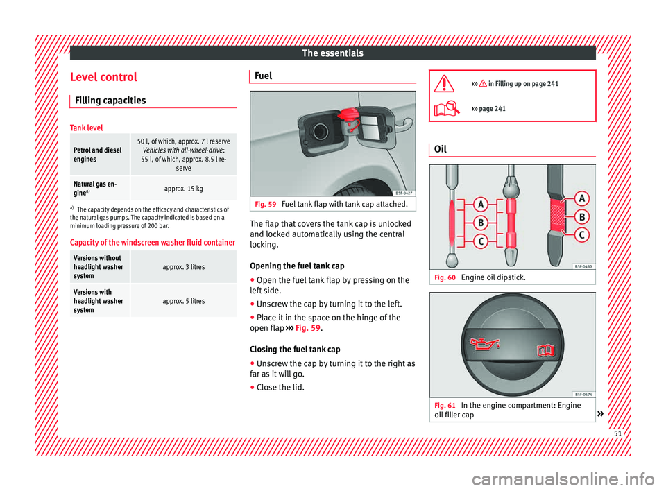
systemapprox. 5 litres Fuel
Fig. 59
Fuel tank flap with tank cap attached. The flap that covers the tank cap is unlocked
and loc
k
ed aut
omatically using the central
locking.
Opening the fuel tank cap
● Open the fuel tank flap by pressing on the
left
side.
● Unscrew the cap by turning it to the left.
● Place it in the space on the hinge of the
open flap ››
› Fig. 59.
Closing the fuel tank cap
● Unscrew the cap by turning it to the right as
far as
it will go.
● Close the lid.
››› in Filling up on page 241
›››
page 241 Oil
Fig. 60
Engine oil dipstick. Fig. 61
In the engine compartment: Engine
oi l
fi
ller cap » 51
Page 64 of 308
The essentials
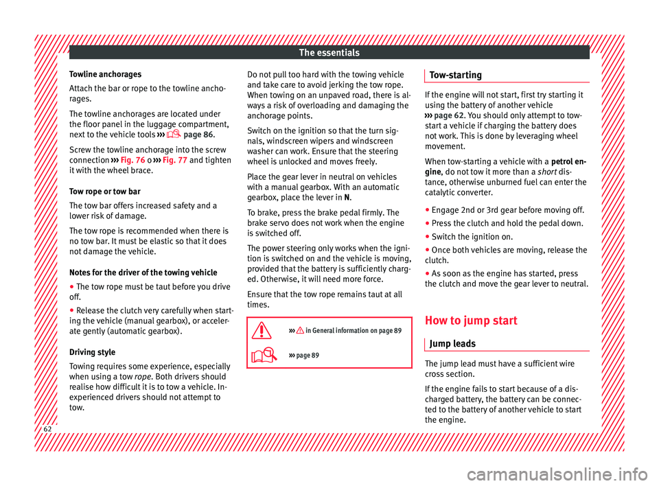
Towline anchorages
Att ac
h the b
ar or rope to the towline ancho-
rages.
The towline anchorages are located under
the floor panel in the luggage compartment,
next to the vehicle tools ›››
page 86.
Screw the towline anchorage into the screw
connection ››› Fig. 76 o ››› Fig. 77 and tighten
it with the wheel brace.
Tow rope or tow bar
The tow bar offers increased safety and a
lower risk of damage.
The tow rope is recommended when there is
no tow bar. It must be elastic so that it does
not damage the vehicle.
Notes for the driver of the towing vehicle
● The tow rope must be taut before you drive
off.
● Rel
ease the clutch very carefully when start-
ing the v
ehicle (manual gearbox), or acceler-
ate gently (automatic gearbox).
Driving style
Towing requires some experience, especially
when using a tow rope. Both drivers should
realise how difficult it is to tow a vehicle. In-
experienced drivers should not attempt to
tow. Do not pull too hard with the towing vehicle
and take c
are to avoid jerking the tow rope.
When towing on an unpaved road, there is al-
ways a risk of overloading and damaging the
anchorage points.
Switch on the ignition so that the turn sig-
nals, windscreen wipers and windscreen
washer can work. Ensure that the steering
wheel is unlocked and moves freely.
Place the gear lever in neutral on vehicles
with a manual gearbox. With an automatic
gearbox, place the lever in N.
To brake, press the brake pedal firmly. The
brake servo does not work when the engine
is switched off.
The power steering only works when the igni-
tion is switched on and the vehicle is moving,
provided that the battery is sufficiently charg-
ed. Otherwise, it will need more force.
Ensure that the tow rope remains taut at all
times.
››› in General information on page 89
››› page 89 Tow-starting
If the engine will not start, first try starting it
us
in
g the battery of another vehicle
››› page 62. You should only attempt to tow-
start a vehicle if charging the battery does
not work. This is done by leveraging wheel
movement.
When tow-starting a vehicle with a petrol en-
gine, do not tow it more than a short dis-
tance, otherwise unburned fuel can enter the
catalytic converter.
● Engage 2nd or 3rd gear before moving off.
● Press the clutch and hold the pedal down.
● Switch the ignition on.
● Once both vehicles are moving, release the
clut c
h.
● As soon as the engine has started, press
the clutc
h and move the gear lever to neutral.
How to jump start Jump lea
ds The jump lead must have a sufficient wire
c
r
o
ss section.
If the engine fails to start because of a dis-
charged battery, the battery can be connec-
ted to the battery of another vehicle to start
the engine. 62
Page 66 of 308
The essentials
Make sure the battery clamps have sufficient
met al-t
o-met
al contact with the battery termi-
nals.
If the engine fails to start after about 10 sec-
onds, switch off the starter and try again after
about 1 minute. WARNING
● Ple a
se note the safety warnings referring to
working in the engine compartment
››› page 246.
● The battery providing assistance must have
the same v
oltage as the flat battery (12V) and
approximately the same capacity (see imprint
on battery). Failure to comply could result in
an explosion.
● Never use jump leads when one of the bat-
teries
is frozen. Danger of explosion! Even af-
ter the battery has thawed, battery acid could
leak and cause chemical burns. If a battery
freezes, it should be replaced.
● Keep sparks, flames and lighted cigarettes
awa
y from batteries, danger of explosion.
Failure to comply could result in an explo-
sion.
● Observe the instructions provided by the
manufact
urer of the jump leads.
● Do not connect the negative cable from the
other vehic
le directly to the negative terminal
of the flat battery. The gas emitted from the
battery could be ignited by sparks. Danger of
explosion. ●
Do not att ac
h the negative cable from the
other vehicle to parts of the fuel system or to
the brake line.
● The non-insulated parts of the battery
clamp
s must not be allowed to touch. The
jump lead attached to the positive battery
terminal must not touch metal parts of the ve-
hicle, this can cause a short circuit.
● Position the leads in such a way that they
cannot c
ome into contact with any moving
parts in the engine compartment.
● Do not lean on the batteries. This could re-
sult
in chemical burns. Note
The vehicles must not touch each other, oth-
erw i
se electricity could flow as soon as the
positive terminals are connected. Changing the wiper blades
W ind
s
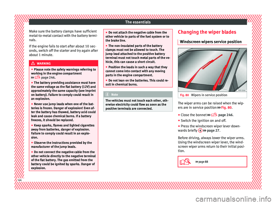
creen wipers service position Fig. 80
Wipers in service position The wiper arms can be raised when the wip-
er
s
ar
e in service position ››› Fig. 80.
● Close the bonnet ›››
page 246.
● Switch the ignition on and off.
● Press the windscreen wiper lever down-
ward
s briefly 4
› ›
› page 27.
Before driving, always lower the wiper arms.
Using the windscreen wiper lever, the wind-
screen wiper arms return to their initial posi-
tion.
››› page 88 64
Page 81 of 308

Airbag system
such as the properties of the object the vehi-
c l
e hits
(hard/soft), angle of impact, vehicle
speed, etc.
Deceleration trajectory is key for airbag acti-
vation.
The control unit analyses the collision trajec-
tory and activates the respective restraint
system.
If the deceleration rate is below the prede-
fined reference value in the control unit the
airbags will not be triggered, even though
the accident may cause extensive damage to
the car.
The following airbags are triggered in seri-
ous head-on collisions
● Driver airbag.
● Front passenger front airbag
● Knee airbag for the driver.
The fol
lowing airbags are triggered in seri-
ous side-on collisions
● Front side airbag on the side of the acci-
dent.
● Re
ar side airbag on the side of the acci-
dent.
● Cur
tain (head) airbag on the side of the ac-
cident. In an ac
cident with airbag activation:
● the interior lights switch on (if the interior
light swit
ch is in the courtesy light position);
● the hazard warning lights switch on;
● all doors are unlocked;
● the fuel supply to the engine is cut.
Airbag safety instructions Front airb
ags Read the additional information carefully
› ›
›
page 17. WARNING
● The deplo yment
space between the front
passengers and the airbags must not in any
case be occupied by other passenger, pets
and objects.
● The airbags provide protection for just one
accident; r
eplace them once they have de-
ployed.
● It is also important not to attach any ob-
jects
such as cup holders or telephone
mountings to the surfaces covering the air-
bag units.
● Do not attempt to modify components of
the airbag sys
tem in any way. Knee airbag*
Read the additional information carefully
›› ›
page 19. WARNING
● The knee airbag i s
deployed in front of the
driver's knees. Always keep the deployment
areas of the knee airbags free.
● Never not fix objects to the cover or in the
deployment
area of the knee airbag.
● Adjust the driver seat so that there is a dis-
tance of
at least 10 cm (4 inches) between
your knees and the location of the this air-
bag. If your physical constitution prevents
you from meeting these requirements, make
sure you contact a specialised workshop. Side airbags*
Read the additional information carefully
› ›
›
page 19. WARNING
● If you do not wear a seat belt, if you lean
for w
ard, or are not seated correctly while the
vehicle is in motion, you are at a greater risk
of injury if the side airbag system is triggered
in an accident.
● In order for the side airbags to provide their
maximum pr
otection, the prescribed sitting » 79
Technical data
Advice
Operation
Emergencies
Safety