ESP Seat Leon 5D 2016 Owner's manual
[x] Cancel search | Manufacturer: SEAT, Model Year: 2016, Model line: Leon 5D, Model: Seat Leon 5D 2016Pages: 324, PDF Size: 6.93 MB
Page 3 of 324
Foreword
This Instruction Manual and its correspond-
in
g s
up
plements should be read carefully to
familiarise yourself with your vehicle.
Besides the regular care and maintenance of
the vehicle, its correct handling will help pre-
serve its value.
For safety reasons, always note the informa-
tion concerning accessories, modifications
and part replacements.
If selling the vehicle, give all of the on-board
documentation to the new owner, as it
should be kept with the vehicle. You can access the information in this man-
ual us
ing:
● Thematic table of contents that follows the
manual’s g
eneral chapter structure.
● Visual table of contents that uses graphics
to indicat
e the pages containing “essential”
information, which is detailed in the corre-
sponding chapters.
● Alphabetical index with many terms and
synonyms
to help you find information. WARNING
Read and always observe safety informa-
tion conc ernin
g the passenger's front air-
bag ››› page 83, Important information
regarding the front passenger's airbag .»
Page 16 of 324
The essentials
››› in Opening or closing the panoramic
sliding sunroof on page 129
››› page 129 Before driving
M anua
l
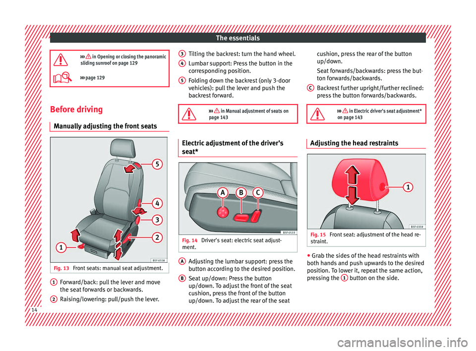
ly adjusting the front seats Fig. 13
Front seats: manual seat adjustment. Forward/back: pull the lever and move
the se
at
f
orwards or backwards.
Raising/lowering: pull/push the lever.
1 2 Tilting the backrest: turn the hand wheel.
L
umb
ar s
upport: Press the button in the
corresponding position.
Folding down the backrest (only 3-door
vehicles): pull the lever and push the
backrest forward.
››› in Manual adjustment of seats on
page 143 Electric adjustment of the driver's
se
at* Fig. 14
Driver's seat: electric seat adjust-
ment . Adjusting the lumbar support: press the
b
utt
on ac
cording to the desired position.
Seat up/down: Press the button
up/down. To adjust the front of the seat
cushion, press the front of the button
up/down. To adjust the rear of the seat
3 4
5
A
B cushion, press the rear of the button
up/do
wn.
Se at
forwards/backwards: press the but-
ton forwards/backwards.
Backrest further upright/further reclined:
press the button forwards/backwards.
››› in Electric driver's seat adjustment*
on page 143 Adjusting the head restraints
Fig. 15
Front seat: adjustment of the head re-
s tr
aint
. ●
Grab the sides of the head restraints with
both h and
s
and push upwards to the desired
position. To lower it, repeat the same action,
pressing the 1 button on the side.
C
14
Page 17 of 324

The essentials
››› in Correct adjustment of front head
restraints on page 69
››› page 69, ››› page 144 Adjustment of the seat belt
Fig. 16
Positioning and removing the seat
belt b
uc
kle. Fig. 17
Correct seat belt and head restraint
pos ition
s, viewed from front and the side. To adjust the seat belt around your should-
er
s, a
dju
st the height of the seats.
The shoulder part of the seat belt should be
well centred over it, never over the neck. The
seat belt lies flat and fits comfortably on the
upper part of the body.
The lap part of the seat belt lies across the
pelvis, never across the stomach. The seat
belt lies flat and fits comfortably on the pel-
vis.
››› page 72
››› page 74 Seat belt tensioners
During a collision, the seat belts on the front
seats
ar
e retracted automatically.
The tensioner can be triggered only once.
››› in Service and disposal of belt ten-
sioners on page 76
››› page 75 Adjusting the exterior mirrors
Fig. 18
Detail of the driver door: control for
the e xt
erior mirr
or. Adjusting the exterior mirrors: Turn the knob
t
o the c
orr
esponding position:
Turning the knob to the desired posi-
tion, adjust the mirrors on the driver »
L/R 15
Page 18 of 324
The essentials
side (L, left) and the passenger side (R,
right) t o the dir
ection de
sired.
Depending on the equipment fitted on
the vehicle, the mirrors may be heated
according to the outside temperature.
Folding in mirrors.
››› in Adjusting the exterior rear view
mirrors on page 142
››› page 142 Adjusting the steering wheel
Fig. 19
Lever in the lower left side of the
s t
eerin
g column. ●
Adjusting the position of the steering
wheel: P u
l
l the ››› Fig. 19 1 lever down,
mo v
e the s
teering wheel to the desired posi-
tion and lift the lever back up until it locks.
››› in Adjusting the steering wheel po-
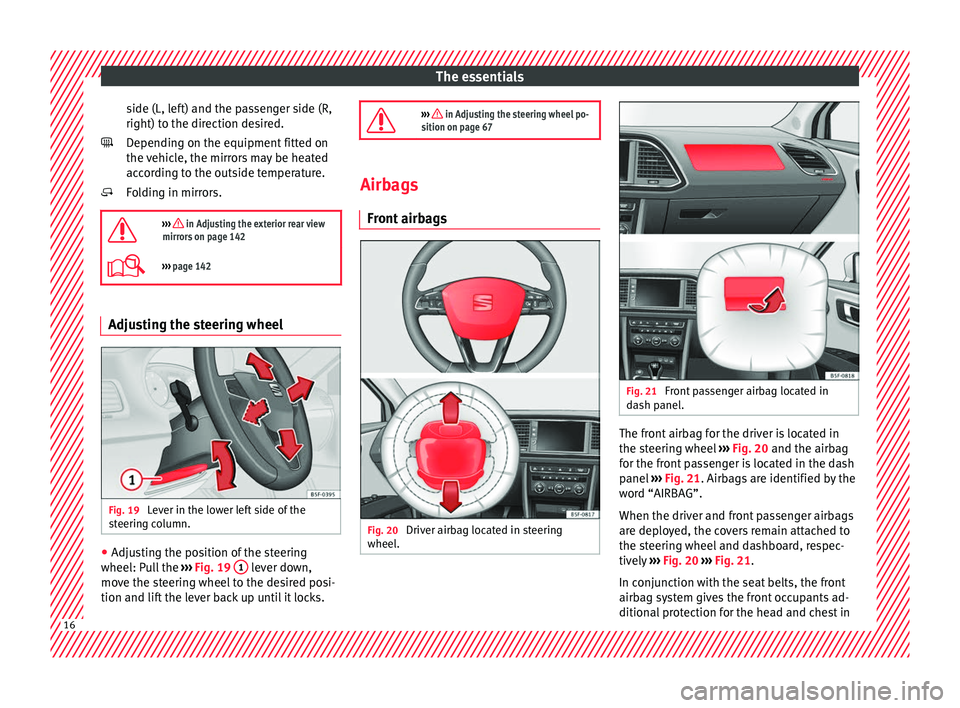
sition on page 67 Airbags
Front airb
ags Fig. 20
Driver airbag located in steering
wheel . Fig. 21
Front passenger airbag located in
d ash p
anel. The front airbag for the driver is located in
the s
t
eerin
g wheel ››› Fig. 20 and the airbag
for the front passenger is located in the dash
panel ››› Fig. 21. Airbags are identified by the
word “AIRBAG”.
When the driver and front passenger airbags
are deployed, the covers remain attached to
the steering wheel and dashboard, respec-
tively ››› Fig. 20 ››› Fig. 21.
In conjunction with the seat belts, the front
airbag system gives the front occupants ad-
ditional protection for the head and chest in 16
Page 25 of 324
The essentials
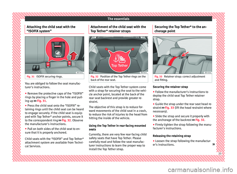
Attaching the child seat with the
“ISOFIX sy
s
tem”Fig. 31
ISOFIX securing rings. You are obliged to follow the seat manufac-
t
ur
er's
instructions.
● Remove the protective caps of the “ISOFIX”
rings
by placing a finger in the hole and pull-
ing up ››› Fig. 31.
● Press the child seat onto the “ISOFIX” re-
taining rin
gs until the child seat can be heard
to engage securely. If the child seat is equip-
ped with Top Tether* anchor points, secure it
to the correspondent ring ››› Fig. 32. Observe
the manufacturer's instructions.
● Pull on both sides of the child seat to en-
sure th
at it is properly anchored.
Child seats with the “ISOFIX” and Top Tether*
attachment system are available from Techni-
cal Services. Attachment of the child seat with the
Top T
ether* retainer straps Fig. 32
Position of the Top Tether rings on the
b ac
k
of the rear seat. Child seats with the Top Tether system come
w
ith a s
tr
ap for securing the seat to the vehi-
cle anchor point, located at the back of the
rear seat backrest and provide greater re-
straint.
The objective of this strap is to reduce for-
ward movements of the child seat in a crash,
to reduce the risk of injuries to the head from
hitting the inside of the vehicle.
Using the Top Tether in rear-facing mounted
seats
Currently, there are very few rear-facing child
safety seats that have Top Tether. Please
carefully read and follow the seat manufac-
turer instructions to learn the proper way to
install the Top Tether strap. Securing the Top Tether* to the an-
chorag
e point Fig. 33
Retainer strap: correct adjustment
and fittin g. Securing the retainer strap
● Follow the manufacturer's instructions to
dep lo
y
the child seat Top Tether retainer
strap.
● Guide the strap under the rear seat head re-
straint
››› Fig. 33 (lift the head restraint where
necessary).
● Slide the strap and secure it properly with
the anchorag
e of the backrest ››› Fig. 32.
● Firmly tighten the strap following the manu-
factur
er's instructions.
Releasing the retaining strap
● Loosen the strap following the manufactur-
er's in s
tructions. » 23
Page 40 of 324
The essentials
you only need to change the oil when the ve-
hic l
e so r
equires. To calculate this change
(max. 2 years), the vehicle's conditions of
use and individual driving styles are consid-
ered. The advance warning first appears 20
days before the date established for the cor-
responding service. The kilometres (miles)
remaining until the next service are always
rounded up to the nearest 100 km (miles)
and the time is given in complete days. The
current service message cannot be viewed
until 500 km after the last service. Prior to
this, only lines are visible on the display.
Inspection reminder
When the Service date is approaching, when
the ignition is switched on a Service remind-
er is displayed.
Vehicles without text messages : a span-
ner will be displayed on the instrument
panel plus an indication in km.
The kilometres indicated are the maximum
number of kilometres that can be travelled
until the next service. After a few seconds,
the display mode changes. A clock symbol
appears and the number of days until the
next service is due.
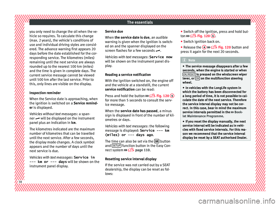
Vehicles with text messages : Service in
--- km or --- days will be shown on the
instrument panel display. Service due
When the servic
e date is due, an audible
warning is given when the ignition is switch-
ed on and the spanner displayed on the
screen flashes for a few seconds .
Vehicles with text messages : Service now
will be shown on the instrument panel dis-
play.
Reading a service notification
With the ignition switched on, the engine off
and the vehicle at a standstill, the current
service notification can be read:
Press and hold the button ›››
Fig. 120
4 for more than 5 seconds to consult the serv-
ic
e me
s
sage.
When the service date has passed , a minus
sign is displayed in front of the number of kil-
ometres or days.
Vehicles with text messages : the following
message is displayed: Service --- km
(miles) or --- days ago .
The time can also be set via the button
and S
ETUP function button in the Easy Con-
nect sy
s
tem ›››
page 110.
Resetting service interval display
If the service was not carried out by a SEAT
dealership, the display can be reset as fol-
lows: ●
Switc
h off the ignition, press and hold but-
ton ›››
Fig. 120
4 .
● Switch ignition back on.
● Release the 4
› ››
Fig. 120
b
utton and
press it again for the next 20 seconds. Note
● The serv ic
e message disappears after a few
seconds, when the engine is started or when OK/RESET is pressed on the windscreen wiper
lev er
, or OK on the multifunction steering
wheel.
● In v
ehicles with the LongLife system in
which the batt
ery has been disconnected for
a long period of time, it is not possible to cal-
culate the date of the next service. Therefore
the service interval display may not be cor- rect. In this case, bear in mind the maximum
service intervals permitted in the ››› Book-
let Maintenance Programme.
● If you reset the display manually, the next
servic
e interval will be indicated as in vehi-
cles with fixed service intervals. For this rea-
son we recommend that the service interval
display be reset by a SEAT authorised Dealer. 38
Page 43 of 324
The essentials
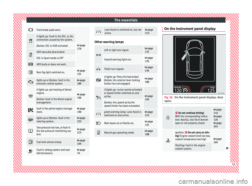
Front brake pads worn.
›››
page
176
it lights up:
Fault in the ESC, or dis-
connection caused by the system.
flashes: ESC or ASR activated.
ASR manually deactivated.
ESC in Sport mode or OFF
ABS faulty or does not work.
Rear fog light switched on.›››
page
131
lights up or flashes:
fault in the
emission control system.››› page
189
it lights up:
pre-heating of diesel
engine.
››› page
190
flashes: fault in the diesel engine
management.
fault in the petrol engine manage-
ment.›››
page
190
lights up or flashes:
fault in the
steering system.››› page
253
Tyre pressure too low, or fault in
the tyre pressure monitoring sys-
tem.›››
page
275
Fuel tank almost empty.›››
page
104
Fault in airbag system and seat
belt tensioners.›››
page
76
Lane Assist is switched on, but not
active.›››
page
213 Other warning lamps
Left or right turn signal.›››
page
131
Hazard warning lights on.››› page
135
Trailer turn signals›››
page
234
it lights up:
Press the foot brake!
flashes: the selector lever locking
button has not engaged.››› page
180
it lights up:
cruise control activated
or speed limiter switched on and
active.
››› page
195
flashes: the speed set by the
speed limiter has been exceeded.
green warning lamp: Lane Assist is
switched on and active.›››
page
213
Main beam on or flasher on.›››
page
131
Natural gas operating mode›››
page
108 On the instrument panel display
Fig. 50
On the instrument panel display: door
open.
Do not continue driving!
With the corresponding indica-
tion: door(s), rear lid or bonnet
open or not properly closed.››› page
116
››› page
126
››› page
262
Ignition: Do not carry on driv-
ing! Engine coolant level too low,
coolant temperature too high
››› page
266
Flashing: Fault in the engine
coolant system.» 41
Page 47 of 324
The essentials
Air conditioning Ho w doe
s
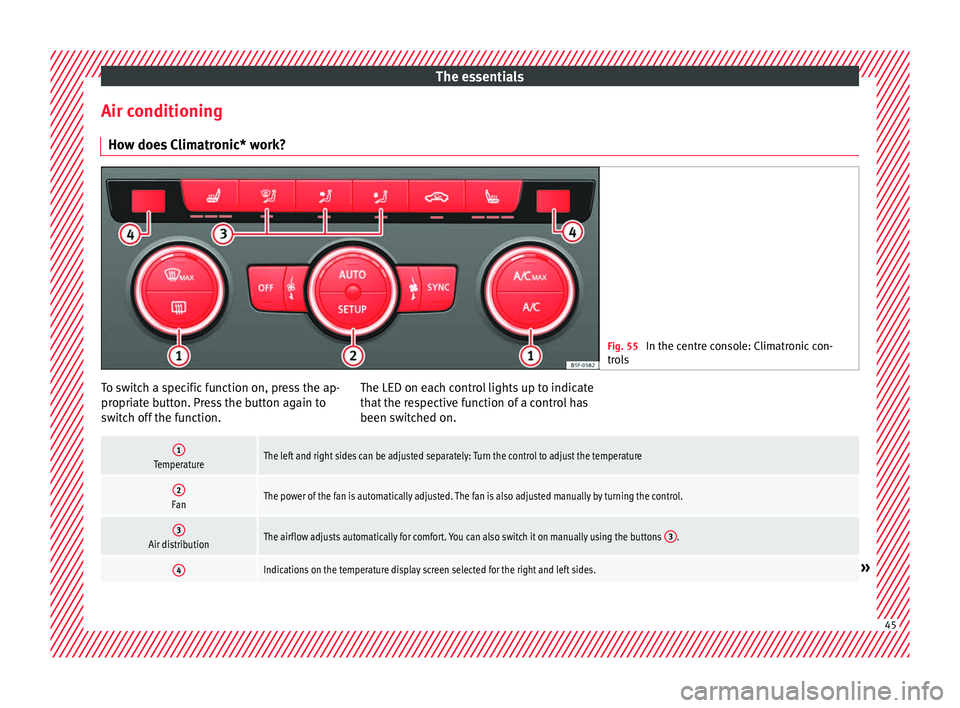
Climatronic* work? Fig. 55
In the centre console: Climatronic con-
tro l
s To switch a specific function on, press the ap-
pr
opri
at
e button. Press the button again to
switch off the function. The LED on each control lights up to indicate
that the r
espective function of a control has
been switched on.
1TemperatureThe left and right sides can be adjusted separately: Turn the control to adjust the temperature
2FanThe power of the fan is automatically adjusted. The fan is also adjusted manually by turning the control.
3Air distributionThe airflow adjusts automatically for comfort. You can also switch it on manually using the buttons 3.
4Indications on the temperature display screen selected for the right and left sides.» 45
Page 49 of 324
The essentials
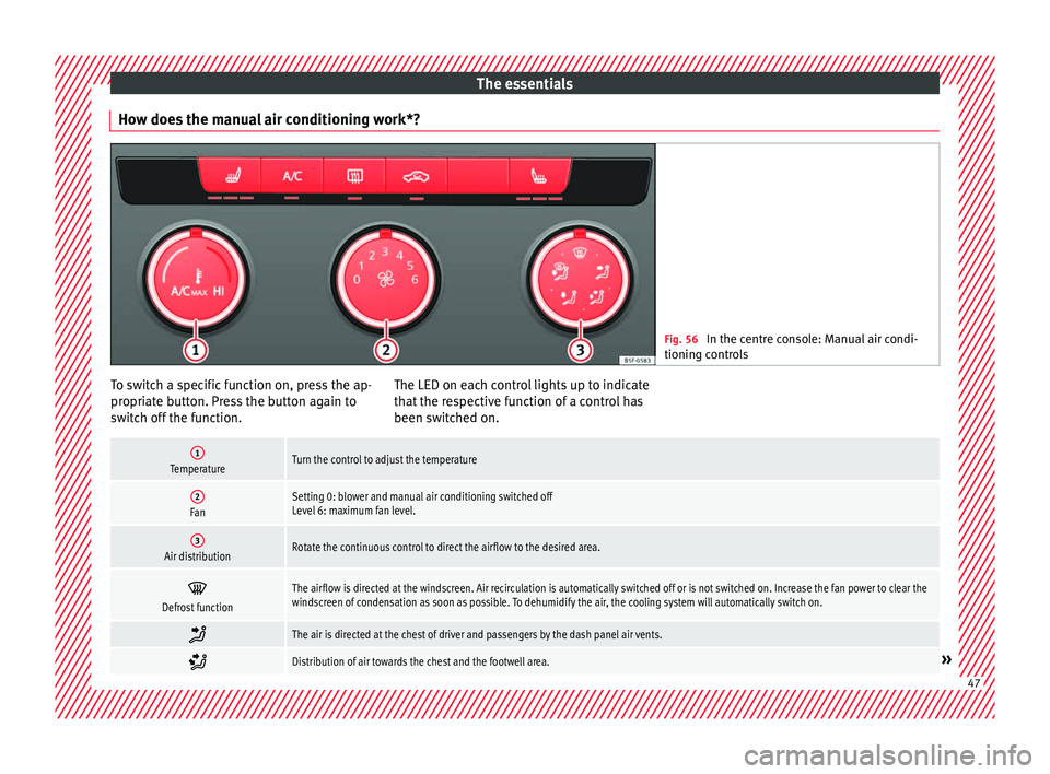
How does the manual air conditioning work*? Fig. 56
In the centre console: Manual air condi-
tioning c ontr
ols To switch a specific function on, press the ap-
pr
opri
at
e button. Press the button again to
switch off the function. The LED on each control lights up to indicate
that the r
espective function of a control has
been switched on.
1TemperatureTurn the control to adjust the temperature
2FanSetting 0: blower and manual air conditioning switched off
Level 6: maximum fan level.
3Air distributionRotate the continuous control to direct the airflow to the desired area.
Defrost functionThe airflow is directed at the windscreen. Air recirculation is automatically switched off or is not switched on. Increase the fan power to clear the
windscreen of condensation as soon as possible. To dehumidify the air, the cooling system will automatically switch on.
The air is directed at the chest of driver and passengers by the dash panel air vents.
Distribution of air towards the chest and the footwell area.»
47
Page 51 of 324
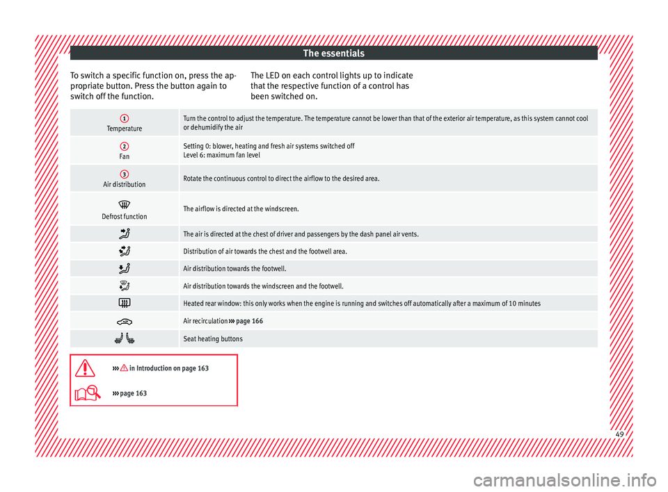
The essentials
To switch a specific function on, press the ap-
pr opri
at
e button. Press the button again to
switch off the function. The LED on each control lights up to indicate
that the r
espective function of a control has
been switched on.
1TemperatureTurn the control to adjust the temperature. The temperature cannot be lower than that of the exterior air temperature, as this system cannot cool
or dehumidify the air
2FanSetting 0: blower, heating and fresh air systems switched off
Level 6: maximum fan level
3Air distributionRotate the continuous control to direct the airflow to the desired area.
Defrost functionThe airflow is directed at the windscreen.
The air is directed at the chest of driver and passengers by the dash panel air vents.
Distribution of air towards the chest and the footwell area.
Air distribution towards the footwell.
Air distribution towards the windscreen and the footwell.
Heated rear window: this only works when the engine is running and switches off automatically after a maximum of 10 minutes
Air recirculation
››› page 166
Seat heating buttons
››› in Introduction on page 163
›››
page 163 49